Table of Contents
Advertisement
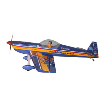
CAP 232
"Graphics and specifications may change without notice".
Specifications
Wing span------------------------------------ 65 in --------------------------------- 165cm.
Wing area------------------------------------782.8 sq.in ------------------- 50.5 sq.dm.
Approximate flying weight---------------- 9.7lbs -------------------------------- 4.4kg.
Length ---------------------------------------- 58.8 in -----------------------------149.4cm.
Recommended engine size------------ .75 - .91 cu.in ------------------- 2-stroke.
ELECTRIC CONVERSION : OPTIONAL.
Radio System required 4 channels with 6 servos.
Flying skill level Intermediate/advanced.
Kit features.
•
Ready-made—minimal assembly & finishing required.
•
Ready-covered covering.
•
Photo-illustrated step-by-step Assembly Manual.
Made in Vietnam.
ASSEMBLY MANUAL
.1.00 - 1.14 cu.in ---------------- 4-stroke.
MS: SEA 91
Advertisement
Table of Contents

Related Manuals for Seagull Models CAP 232


Summary of Contents for Seagull Models CAP 232
- Page 1 CAP 232 MS: SEA 91 ASSEMBLY MANUAL “Graphics and specifications may change without notice”. Specifications Wing span------------------------------------ 65 in --------------------------------- 165cm. Wing area------------------------------------782.8 sq.in ------------------- 50.5 sq.dm. Approximate flying weight---------------- 9.7lbs -------------------------------- 4.4kg. Length ---------------------------------------- 58.8 in -----------------------------149.4cm. Recommended engine size------------ .75 - .91 cu.in ------------------- 2-stroke.
-
Page 2: Fuselage Assembly
CAP 232. INTRODUCTION. Thank you for choosing the CAP 232 ARTF by SEAGULL MODELS. The CAP 232 was designed with the intermediate/advanced sport scale in mind. It is a semi scale airplane which is easy to fly and quick to assemble. The airframe is conventionally built using balsa, plywood to make it stronger than the average ARTF , yet the design allows the aeroplane to be kept light. -
Page 3: Hinging The Ailerons
This will ensure proper assembly as the CAP 232 is made from natural materials and minor adjustments may have to be made. The paint and plastic parts used in this kit are fuel proof. -
Page 4: Hinging The Elevator
Instruction Manual CAP 232. 7) Repeat this process with the other wing AILERON CONTROL HORN panel, securely hinging the aileron in place. 8) After both ailerons are securely hinged, Aileron control horn installation: See pictures firmly grasp the wing panel and aileron to... -
Page 5: Rudder Control Horn
www.seagullmodels.com ELEVATOR CONTROL HORN. 2 sets. Install the elevator control horn using the same method as with the aileron control horns. 2 sets. 3x45mm. 3x35mm. CONTROL HORN M3 SCREW CONTROL HORN M3 ALUMINUM WASHER EPOXY. Aluminum Washer Epoxy Rudder FUSELAGE Horizontal Elevator. -
Page 6: Engine Mount Installation
Instruction Manual CAP 232. ENGINE MOUNT INSTALLATION. INSTALLING THE STOPPER ASSEMBLY. See pictures below.Make yourself the 1) Using a modeling knife, carefully cut template of your engine on paper. off the rear portion of one of the 3 nylon tubes leaving 1/2”... -
Page 7: Installing The Battery
www.seagullmodels.com Vent tube. Fuel pick up tube. Rubber band. Fuel fill tube. Carefully use a lighter or heat gun to permenently set the angle of the vent tube. Important: When the stopper assembly is in- Fuel tank. stalled in the tank, the top of the vent tube should rest just below the top surface of the tank. -
Page 8: Installing The Main Landing Gear
Instruction Manual CAP 232. Landing Gear. wheel Pant. C/A glue. 2) Follow diagram below for wheel pant installation: 7mm. 14mm. Locker glue. Lite-Plywood wheel collar. block. 3) A drop of C/A glue on the wheel collar screws will help keep them from coming lose during operation. -
Page 9: Mounting The Engine
www.seagullmodels.com 5) Bolt the engine to the engine mount using MOUNTING THE ENGINE. the four machine screws. Double check that all the screws are tight before proceeding. 1) Install the pushrod housing through the predrilled hole in the firewall and into the servo 6) Attach the Z-Bend in the pushrod wire to compartment. - Page 10 Instruction Manual CAP 232. Trim and cut. Electric Conversion (Ep Power) (OPTION). Because of the size of the cowl, it may be nec- essary to use a needle valve extension for the high speed needle valve. Make this out of suf- ficient length 1.5mm wire and install it into the...
- Page 11 www.seagullmodels.com M3x15mm. M5 x 100mm. Battery hatch. M3x10mm. Electric motor. C/A glue. Electric motor. 140mm. C/A glue. 4 sets. Aluminum tube. Aluminum spacers. Electric motor. Battery. Aluminum tube.
-
Page 12: Spinner Installation
Instruction Manual CAP 232. SPINNER INSTALLATION. Battery hatch. needle valve. Pen. Machine Screw M3x10mm Trim and cut. INSTALLING THE SWITCH. Install the switch into the precut hole in the side of fuselage. Battery hatch. M3x10mm. Switch. -
Page 13: Installing The Aileron Servos
www.seagullmodels.com INSTALLING THE FUSELAGE SERVO. INSTALLING THE AILERON SERVOS. Elevator servo . Servos. Small weight. Rudder servo . Throttle servo . Thread. Elevator servo . Installing the aileron servo in place using the same techniques used to flap servo. THROTTLE SERVO ARM INSTALLATION. Install adjustable servo connector in the servo arm . -
Page 14: Wing Assembly
Instruction Manual CAP 232. AILERON PUSHROD HORN INSTALLATION Wing. 85mm. M3 clevis. M3 lock nut. Aileron. 115mm. Wing Wing Aileron Aileron Wing. M3 lock nut. Epoxy. Aileron. Repeat the procedure for the other wing. WING ASSEMBLY. -
Page 15: Installing The Horizontal Stabilizer
www.seagullmodels.com Remove covering. When cutting through the covering to remove it, cut with only enough pressure to only cut through the covering itself. Cut- INSTALLING THE HORIZONTAL STABILIZER. ting into the balsa structure may weaken Epoxy. Remove the covering. Center line. Hinge slot. -
Page 16: Installing The Vertical Stabilizer
Instruction Manual CAP 232. INSTALLING THE VERTICAL STABILIZER. Hinge. Masking tape. Remove covering. Epoxy. Fill epoxy. Hinge. C/A glue. Vertical Stabilizer. Horizontal 90º Stabilizer. Masking tape. - Page 17 www.seagullmodels.com Control horn. M2 lock nut. Metal clevis. Elevator Pushrod. ELEVATOR - RUDDER PUSHROD HORN INSTALLATION. Rudder pushrod. Rudder control horn. Elevator pushrod. Elevator control horn. M2 clevis. M2 Lock nut. Attach to elevator - rudder control horn. Attach to servo arm in fuselage.
-
Page 18: Mounting The Tail Wheel
Instruction Manual CAP 232. Throttle. Elevator. Rudder. Elevator. M3x25 mm. Rudder. Rudder. Throttle. Elevator. 22mm. M3x30 mm. MOUNTING THE TAIL WHEEL. See picture below. M3x30 mm. M3x30mm. M3x25mm. - Page 19 www.seagullmodels.com INSTALLTION PILOT. Receiver. Remove covering and glue bond. Antenna. 60mm. ATTACHMENT WING - FUSELAGE. Bolt the wing to fuselage.See pictures below. Wing bolt. Wing bolt. BALANCING. 1) It is critical that your airplane be bal- M2x6mm. anced correctly. Improper balance will cause your plane to lose control and crash.
-
Page 20: Control Throws
2) Check every bolt and every glue joint to the clevises or adjustable servo connectors. in the CAP 232 to ensure that everything is The servo arms should be centered also. tight and well bonded. - Page 21 8) Properly balance the propeller. An out of balance propeller will cause excessive vi- bration which could lead to engine and/or air- frame failure. We wish you many safe and enjoyable flights with your CAP 232. INITIAL FLYING AEROBATIC FLYING...
Need help?
Do you have a question about the CAP 232 and is the answer not in the manual?
Questions and answers