H3C S3600 Series Installation Manual
Hide thumbs
Also See for S3600 Series:
- Command manual (1277 pages) ,
- Operation manual (966 pages) ,
- Installation manual (68 pages)

Related Manuals for H3C S3600 Series


Summary of Contents for H3C S3600 Series
- Page 1 H3C S3600 Series Ethernet Switches Installation Manual Hangzhou H3C Technologies Co., Ltd. http://www.h3c.com Manual Version: T2-08045V-20070517-C-1.04...
- Page 2 Copyright © 2006-2007, Hangzhou H3C Technologies Co., Ltd. and its licensors All Rights Reserved No part of this manual may be reproduced or transmitted in any form or by any means without prior written consent of Hangzhou H3C Technologies Co., Ltd.
-
Page 3: About This Manual
About This Manual Related Documentation In addition to this manual, each H3C S3600 Series Ethernet Switches documentation set includes the following: Manual Description It guides users to use H3C S3900 Series Ethernet Switches, in respect of CLI, login, configuration file management,... - Page 4 Introduces how to load BootROM and 5 Loading Boot ROM and Host Software host software for an S3600 Series Ethernet Switch. Introduces the problems that might occur during the installation and the...
- Page 5 Environmental Protection This product has been designed to comply with the requirements on environmental protection. For the proper storage, use and disposal of this product, national laws and regulations must be observed.
-
Page 6: Table Of Contents
1.9 S3600-52P-PWR-SI/S3600-52P-PWR-EI ............... 1-34 1.9.1 Front Panel......................1-34 1.9.2 Rear Panel ......................1-36 1.10 Features of the S3600 Series ..................1-37 1.10.1 Features of the S3600-SI ..................1-37 1.10.2 Features of the S3600-EI ..................1-38 1.10.3 Features of the S3600-PWR-SI/S3600-PWR-EI..........1-39 Chapter 2 Preparation ........................ - Page 7 Installation Manual H3C S3600 Series Ethernet Switches Table of Contents 2.3 Installation Tools ........................ 2-3 Chapter 3 Installation ........................3-1 3.1 Mounting the Switch ......................3-1 3.1.1 Mounting the Switch into a 19-Inch Standard Cabinet..........3-1 3.1.2 Mounting the Switch on a Desktop/Workbench ............ 3-10 3.2 Connecting the Power Cord and the Ground Wire ............
- Page 8 Installation Manual H3C S3600 Series Ethernet Switches Table of Contents Chapter 6 Maintenance and Troubleshooting ................6-1 6.1 Dealing with Loading Failures.................... 6-1 6.2 Dealing with Password Loss....................6-1 6.2.1 Dealing with User Password Loss................6-1 6.2.2 Recovering the Boot ROM Password ..............6-2 6.3 Dealing with Power System Failures .................
-
Page 9: Chapter 1 Product Overview
H3C S3600 Series Ethernet Switches developed by H3C are high-performance, high-density, easy-to-install, NMS-manageable intelligent Ethernet switches which support wire-speed Layer 2/3 switching. Table 1-1 lists the models of H3C S3600 Series Ethernet Switches. Table 1-1 Models of the S3600 series Number... - Page 10 Installation Manual H3C S3600 Series Ethernet Switches Chapter 1 Product Overview Number Number Number of 1000 Number of Power Subseries Model 100 Mbps Mbps supply service Console ports uplink ports ports ports 24 × 4 × 10Base-T/ S3600-2 1000Bas AC/DC...
-
Page 11: S3600-28P-Si
Installation Manual H3C S3600 Series Ethernet Switches Chapter 1 Product Overview 1.2 S3600-28P-SI 1.2.1 Front Panel I. Schematic diagram The S3600-28P-SI provides twenty-four 10Base-T/100Base-TX auto-sensing Ethernet ports, four 1000Base-X SFP ports, and one Console port on the front panel, as shown in Figure 1-1. - Page 12 Installation Manual H3C S3600 Series Ethernet Switches Chapter 1 Product Overview Mark Status Indication Solid green The switch is started normally. The system is running a power-on Flashing green (1 Hz) self-test (POST) or downloading software. Power The system fails a POST or a fault Solid red occurs.
- Page 13 Installation Manual H3C S3600 Series Ethernet Switches Chapter 1 Product Overview Mark Status Indication A 1000 Mbps link is present. Green Data is being received/sent on Flash the port. Speed Flashing yellow The port fails POST. (3 Hz) No link is present.
- Page 14 Installation Manual H3C S3600 Series Ethernet Switches Chapter 1 Product Overview Mark Status Indication POST The PWR LED Displays the POST test ID (in the running flashes green range of 1 to 9). The PWR LED flashes yellow POST Flashes the POST test ID of the failed failed test.
-
Page 15: Rear Panel
The types of 1000Base-X SFP modules may be subject to changes without notice. Consult H3C marketing personnel or technical support personnel to obtain the latest information about SFP modules. For specifications of SFP modules, refer to H3C Low End Series Ethernet Switches Pluggable Modules Manual. 1.2.2 Rear Panel I. -
Page 16: S3600-28Tp-Si
Installation Manual H3C S3600 Series Ethernet Switches Chapter 1 Product Overview (1) (1) (2) (2) (1) AC power socket (2) Grounding screw Figure 1-2 Rear panel of the S3600-28P-SI II. Power system The following gives the input voltage specifications for the S3600-28P-SI:... - Page 17 Installation Manual H3C S3600 Series Ethernet Switches Chapter 1 Product Overview LEDs, two 1000Base-X SFP port status LEDs, and two 10/100/1000Base-T auto-sensing Ethernet port status LEDs. You can learn how the switch operates by observing the LEDs listed in Table 1-6.
- Page 18 Installation Manual H3C S3600 Series Ethernet Switches Chapter 1 Product Overview Mark Status Indication A 1000 Mbps link is present. Gree Flas Data is being received/sent on the hing port. Speed Flashing The port fails a POST. yellow (3Hz) No link is present.
- Page 19 The types of 1000Base-X SFP modules may be subject to changes without notice. Consult H3C marketing personnel or technical support personnel to obtain the latest information about SFP modules. For specifications of SFP modules, refer to H3C Low End Series Ethernet Switches Pluggable Modules Manual. 1-11...
-
Page 20: Rear Panel
Installation Manual H3C S3600 Series Ethernet Switches Chapter 1 Product Overview V. Attributes of the 10/100/1000Base-T Ethernet ports The S3600-28TP-SI can provide two 10/100/1000Base-T Ethernet ports numbered 27 and 28 on the front panel. For attributes of these two ports, see Table 1-7. -
Page 21: S3600-52P-Si
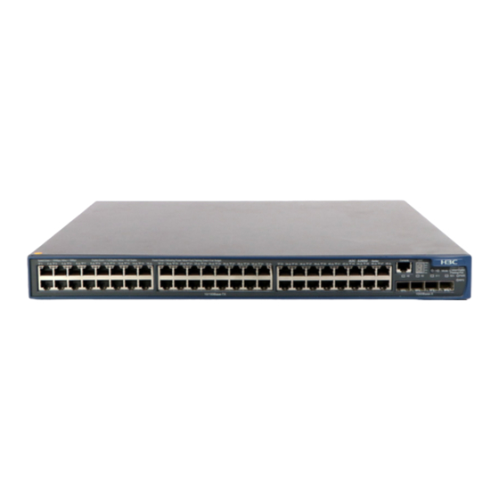
Installation Manual H3C S3600 Series Ethernet Switches Chapter 1 Product Overview 1.4 S3600-52P-SI 1.4.1 Front Panel I. Schematic diagram On the front panel, the S3600-52P-SI provides forty-eight 10Base-T/100Base-TX auto-sensing Ethernet ports, four 1000Base-X SFP ports, and one Console port, as shown in Figure 1-5. -
Page 22: Rear Panel
The types of 1000Base-X SFP modules may be subject to changes without notice. Consult H3C marketing personnel or technical support personnel to obtain the latest information about SFP modules. For specifications of SFP modules, refer to H3C Low End Series Ethernet Switches Pluggable Modules Manual. 1.4.2 Rear Panel I. -
Page 23: S3600-28P-Ei
Installation Manual H3C S3600 Series Ethernet Switches Chapter 1 Product Overview II. Power system The following gives the input voltage specifications for the S3600-52P-SI: Rated voltage range: 100 VAC to 240 VAC, 50/60 Hz Input voltage range: 90 VAC to 264 VAC, 47 to 63 Hz 1.5 S3600-28P-EI... - Page 24 Installation Manual H3C S3600 Series Ethernet Switches Chapter 1 Product Overview Table 1-9 LEDs on the front panel of the S3600-28P-EI Mark Status Indication The system passes the Solid green Power-On Self-Test (POST) and is operating normally. The system is running a POST or Flashing green (1 Hz) is downloading software.
- Page 25 Installation Manual H3C S3600 Series Ethernet Switches Chapter 1 Product Overview Mark Status Indication A 100 Mbps link is present. Green Data is being received/sent on Flash the port A 10 Mbps link is present. Speed Yellow Data is being received/sent on...
- Page 26 Installation Manual H3C S3600 Series Ethernet Switches Chapter 1 Product Overview Mark Status Indication The port is connected, and the device is in an IRF loop fabric. Green Data is being received/sent on Flash the port. The port is connected and the device is in an IRF chain fabric.
-
Page 27: Rear Panel
The types of 1000Base-X SFP modules may be subject to changes without notice. Consult H3C marketing personnel or technical support personnel to obtain the latest information about SFP modules. For specifications of SFP modules, refer to H3C Low End Series Ethernet Switches Pluggable Modules Manual. 1.5.2 Rear Panel I. - Page 28 Installation Manual H3C S3600 Series Ethernet Switches Chapter 1 Product Overview (1) 100Base-X SFP port status LEDs (2) 1000Base-X SFP port status LEDs (3) 10/100/1000Base-T auto-sensing Ethernet port status LEDs (4) Console port (5) 7-segment digital LED (6) DC power LED...
- Page 29 Installation Manual H3C S3600 Series Ethernet Switches Chapter 1 Product Overview Mark Color Indicates Rate information of the 10Base-T/100Base-TX Speed Solid green Ethernet ports and the 1000Base-X SFP ports. Mode Mode Duplex information of 10Base-T/100Base-TX Duplex Solid yellow Ethernet ports and the 1000Base-X SFP ports.
- Page 30 Installation Manual H3C S3600 Series Ethernet Switches Chapter 1 Product Overview Mark Color Indicates A 1000 Mbps link is present. Green Data is being received/sent on Flash the port Speed Flashing yellow The port fails POST. (3 Hz) No link is present.
- Page 31 Installation Manual H3C S3600 Series Ethernet Switches Chapter 1 Product Overview Mark Color Indicates A 1000 Mbps link is present. Green Data is being received/sent on Flash the port A 10/100 Mbps link is present. Speed Yellow Data is being received/sent on...
- Page 32 Installation Manual H3C S3600 Series Ethernet Switches Chapter 1 Product Overview Mark Color Indicates The port is connected, and the device is in an IRF loop fabric. Green Data is being received/sent on Flash the port The port is connected, and the device is in an IRF chain fabric.
-
Page 33: Rear Panel
The types of 1000Base-X SFP modules may be subject to changes without notice. Consult H3C marketing personnel or technical support personnel to obtain the latest information about SFP modules. For specifications of SFP modules, refer to H3C Low End Series Ethernet Switches Pluggable Modules Manual. V. Attributes of the 10/100/1000Base-T Ethernet ports The S3600-28F-EI provides two 10/100/1000Base-T Ethernet ports numbered 27 and 28 on the front panel. -
Page 34: S3600-52P-Ei
Installation Manual H3C S3600 Series Ethernet Switches Chapter 1 Product Overview (1) AC power socket (2) DC power socket (3) Grounding screw Figure 1-10 Rear panel of the S3600-28F-EI II. Power system AC power Rated voltage range: 100 VAC to 240 VAC, 50 Hz/60 Hz... -
Page 35: Rear Panel
The types of 1000Base-X SFP modules may be subject to changes without notice. Consult H3C marketing personnel or technical support personnel to obtain the latest information about SFP modules. For specifications of SFP modules, refer to H3C Low End Series Ethernet Switches Pluggable Modules Manual. V. Console port The S3600-52P-EI provides one EIA/TIA-232 compliant Console port for local or remote switch configuration. -
Page 36: S3600-28P-Pwr-Si/S3600-28P-Pwr-Ei
Installation Manual H3C S3600 Series Ethernet Switches Chapter 1 Product Overview II. Power system AC power Rated voltage range: 100 VAC to 240 VAC, 50 Hz/60 Hz Input voltage range: 90 VAC to 264 VAC, 47 Hz to 63 Hz DC power Rated voltage range: –48 VDC to –60 VDC... - Page 37 Installation Manual H3C S3600 Series Ethernet Switches Chapter 1 Product Overview Table 1-12 LEDs on the front panel of the S3600-28P-PWR-SI/S3600-28P-PWR-EI Mark Color Indicates The system passes a POST Solid green and is operating normally. The system is running a POST Flashing green (1 Hz) or is downloading software.
- Page 38 Installation Manual H3C S3600 Series Ethernet Switches Chapter 1 Product Overview Mark Color Indicates POST PWR flashes Flashes the POST test ID of the running green failed test. PWR flashes POST test ID of the failed test. POST yellow A bar rotates clockwise around failed the LED.
- Page 39 Installation Manual H3C S3600 Series Ethernet Switches Chapter 1 Product Overview Mark Color Indicates A 100 Mbps link is present. Green Data is being received/sent on Flash the port A 10 Mbps link is present. Speed Yellow Data is being received/sent on...
- Page 40 Installation Manual H3C S3600 Series Ethernet Switches Chapter 1 Product Overview Mark Color Indicates A 1000 Mbps link is present. Green Data is being received/sent on Flash the port Speed Flashing yellow The port fails POST. (3 Hz) No link is present.
- Page 41 The types of 1000Base-X SFP modules may be subject to changes without notice. Consult H3C marketing personnel or technical support personnel to obtain the latest information about SFP modules. For specifications of SFP modules, refer to H3C Low End Series Ethernet Switches Pluggable Modules Manual. V. Console port The S3600-28P-PWR-SI/S3600-28P-PWR-EI provides one EIA/TIA-232 compliant Console port for local or remote switch configuration.
-
Page 42: Rear Panel
Installation Manual H3C S3600 Series Ethernet Switches Chapter 1 Product Overview 1.8.2 Rear Panel I. Schematic diagram The S3600-28P-PWR-SI/S3600-28P-PWR-EI provides an AC power socket, a DC power socket and a grounding screw on its rear panel, as shown in Figure 1-14. - Page 43 Installation Manual H3C S3600 Series Ethernet Switches Chapter 1 Product Overview (1) 10Base-T/100Base-TX auto-sensing Ethernet port status LEDs (2) Console port (3) 7-segment digital LED (4) Mode button (5) Mode LED (6) AC Power LED (7) DC power LED (8) 1000Base-X SFP port status LED Figure 1-15 Front panel of the S3600-52P-PWR-SI/S3600-52P-PWR-EI II.
-
Page 44: Rear Panel
The types of 1000Base-X SFP modules may be subject to changes without notice. Consult H3C marketing personnel or technical support personnel to obtain the latest information about SFP modules. For specifications of SFP modules, refer to H3C Low End Series Ethernet Switches Pluggable Modules Manual. V. Console port The S3600-52P-PWR-SI/S3600-52P-PWR-EI provides one EIA/TIA-232 compliant Console port for local or remote switch configuration. -
Page 45: Features Of The S3600 Series
Only the recommended PoE power supply can be used for S3600-28P-PWR-SI, S3600-28P-PWR-EI, S3600-52P-PWR-SI, and S3600-52P-PWR-EI. The –48 VDC from the equipment room cannot be used directly. Otherwise, the device may be damaged. 1.10 Features of the S3600 Series 1.10.1 Features of the S3600-SI Table 1-15 Features of the S3600-SI Item... -
Page 46: Features Of The S3600-Ei
Installation Manual H3C S3600 Series Ethernet Switches Chapter 1 Product Overview Item S3600-28P-SI S3600-28TP-SI S3600-52P-SI System power consumption (full 40 W 40 W 50 W load) Operating 0°C to 45°C (32°F to 113°F) temperature Relative humidity 10% to 90% (noncondensing) 1.10.2 Features of the S3600-EI... -
Page 47: Features Of The S3600-Pwr-Si/S3600-Pwr-Ei
Installation Manual H3C S3600 Series Ethernet Switches Chapter 1 Product Overview 1.10.3 Features of the S3600-PWR-SI/S3600-PWR-EI Table 1-17 Features of the S3600-PWR-SI/S3600-PWR-EI S3600-28P-PWR-SI S3600-52P-PWR-SI Item S3600-28P-PWR-EI S3600-52P-PWR-EI Physical dimensions 43.6 × 440 × 420 (1.7 × 17.3 × 16.5 in) (H ×... -
Page 48: Chapter 2 Preparation
When replacing interface cards, wear an ESD-preventive wrist strap to avoid damaging the cards. 2.2 Installation Site The S3600 series must be used indoors. You can mount your switch in a rack or on a desktop/workbench, but make sure: Adequate clearance is reserved at the air inlet/exhaust vents for ventilation. -
Page 49: Cleanness
For the temperature and humidity requirements of different models, refer to section 1.10 “Features of the S3600 Series”. 2.2.2 Cleanness Dust is a hazard to the operating safety of your device. The dust accumulated on the chassis can be adsorbed by static electricity and result in poor contact of metal connectors or metal contact points. -
Page 50: Installation Tools
Caution: Staring into the laser beam produced by the fiber can hurt your eyes. 2.3 Installation Tools Flat-blade screwdriver Phillips screwdriver ESD-preventive wrist strap Caution: The installation tools are not provided with the S3600 series. -
Page 51: Chapter 3 Installation
Installation Manual H3C S3600 Series Ethernet Switches Chapter 3 Installation Chapter 3 Installation Caution: When you ask your sales agent to maintain the switch, you must ensure that the dismantlement-preventive seal on a mounting screw of the switch chassis is intact. If you want to open the chassis, you should contact the agent for permission. - Page 52 When the depth of a switch is greater than 300 mm (11.8 in), the front mounting ears only secure the switch rather than bear its weight. Guide rails purchased from H3C apply only to standard cabinets 1,000 mm (39.4 in) deep. Use other supports to substitute for guide rails in the case of other cabinet depths.
- Page 53 Installation Manual H3C S3600 Series Ethernet Switches Chapter 3 Installation When you install S3600 series into 19” standard cabinets, you should select front and rear mounting ears listed in Table 3-2. Table 3-2 Selection of mounting ears for the S3600 series...
- Page 54 Installation Manual H3C S3600 Series Ethernet Switches Chapter 3 Installation Front square-holed bracket Front square-holed bracket Front mounting ear Front mounting ear Front panel Front panel Front Front mounting ear mounting ear Figure 3-4 Fix front mounting ears (2) III. Use front mounting ears and a tray...
- Page 55 Installation Manual H3C S3600 Series Ethernet Switches Chapter 3 Installation Three installation locations for screw 1 (select one according to the actual requirement) Three installation locations for screw 1 (select one according to the actual requirement) Screw 1 Screw 1...
- Page 56 Installation Manual H3C S3600 Series Ethernet Switches Chapter 3 Installation Hold the bottom of the switch with one hand and the front part of the switch with the other hand, and pull the switch into the cabinet gently, as shown in Figure 3-7.
- Page 57 Installation Manual H3C S3600 Series Ethernet Switches Chapter 3 Installation Screw 1 Rear mounting ear Front panel Front mounting ear Front square-holed bracket Screw 1: Load-bearing screw Figure 3-9 Effect diagram of front and rear mounting ear installation (2) V. Use front mounting ears and guide rails Introduction to guide rail Figure 3-10 shows the appearance of a guide rail.
- Page 58 H3C S3600 Series Ethernet Switches Chapter 3 Installation Note: Guide rails purchased from H3C apply only to standard cabinets 1,000 mm (39.4 in) deep. Use other supports to substitute for guide rails in the case of other cabinet depths. Installation procedure...
- Page 59 Installation Manual H3C S3600 Series Ethernet Switches Chapter 3 Installation Front panel Figure 3-12 Install front mounting ears and guide rails Fix the other end of front mounting ears to the front brackets of the cabinet with M6 screws and captive nuts and ensure that the front mounting ears and guide rails have fixed the switch in the cabinet securely, as shown in Figure 3-13.
-
Page 60: Mounting The Switch On A Desktop/Workbench
Installation Manual H3C S3600 Series Ethernet Switches Chapter 3 Installation Note: No guide rails are delivered with the device. Ensure a clearance of 1U (44.45 mm, namely, 1.75 inches) between devices for the purpose of heat dissipation. 3.1.2 Mounting the Switch on a Desktop/Workbench When placing the switch on a desktop or workbench, you simply need to: Make sure that the desktop or workbench is clean, flat, and sturdy. -
Page 61: Connecting The Dc-Input Power Cord
Installation Manual H3C S3600 Series Ethernet Switches Chapter 3 Installation Step 3: Check that the PWR LED on the front panel of the switch is ON. Caution: Before powering on the switch, connect the ground wire. 3.2.2 Connecting the DC-Input Power Cord +... - Page 62 Installation Manual H3C S3600 Series Ethernet Switches Chapter 3 Installation Fix the dust-proof shield by screws 3 and 4 by using a small flathead screwdriver, see Figure 3-16. Enlace the two cables to the polarizing key at the back of the dust-proof shield using the cable tie, see Figure 3-16.
-
Page 63: Connecting The Ground Wire
Installation Manual H3C S3600 Series Ethernet Switches Chapter 3 Installation 3.2.3 Connecting the Ground Wire Caution: Correctly connecting the switch ground wire is crucial to the lightning protection and electromagnetic susceptibility (EMS) of a switch. The power input end of the switch is connected with a noise filter, whose central ground is directly connected to the chassis, forming the chassis ground (commonly known as PGND). - Page 64 Installation Manual H3C S3600 Series Ethernet Switches Chapter 3 Installation (1) Power input (2) Grounding screw (3) Ground wire (4) Earth (5) Angle iron Figure 3-19 Grounding the switch by burying the grounding body into the earth For an AC-powered switch, if none of the above two conditions is available, ground it through the PE wire of the AC power supply.
-
Page 65: Multi-Power Input
Installation Manual H3C S3600 Series Ethernet Switches Chapter 3 Installation (11) (11) (10) (10) (1) AC/DC power cabinet (2) –48V strip (3) –48V (4) RTN strip (5) RTN (6) PGND strip (7) Grounding (8) Ground wire (9) Grounding screw (10) Ethernet switch... -
Page 66: Connecting The Switch To A Console Terminal
Installation Manual H3C S3600 Series Ethernet Switches Chapter 3 Installation 3.4 Connecting the Switch to a Console Terminal 3.4.1 Console Cable Console cable is an 8-core cable. At one end of the cable is a crimped RJ-45 connector for the connection to the Console port of the switch; at the other end of the cable are one DB-9 (female) connector for the connection to the serial port on the console terminal. -
Page 67: Connecting And Removing Special Stack Interconnect Cables
As shown in Figure 3-23, the special stack interconnect cables, 1.5 meters (59.1 in) long, are used to connect fabric ports (1000Base-X SFP ports on the front panel) in an intelligent resilient framework (IRF) consisting of multiple S3600 series. (1) Connector of special stack interconnect cables... -
Page 68: Removing Special Stack Interconnect Cables
Installation Manual H3C S3600 Series Ethernet Switches Chapter 3 Installation Wear an ESD-preventive wrist strap and check that it is well grounded. Take the special stack interconnect cables out of the pack. Insert the connector horizontally into the fabric port of the switch, with the front side facing upwards. -
Page 69: Chapter 4 Starting Up The Switch At The Initial Boot
Installation Manual H3C S3600 Series Ethernet Switches Chapter 4 Starting up the Switch at the Initial Boot Chapter 4 Starting up the Switch at the Initial Boot 4.1 Setting up a Configuration Environment Set up a configuration environment as shown in Figure 4-1. - Page 70 Installation Manual H3C S3600 Series Ethernet Switches Chapter 4 Starting up the Switch at the Initial Boot Step 1: Start the PC and select [Start/Programs/Accessories/Communications/HyperTe rminal]. The HyperTerminal window displays the Connection Description dialog box, as shown in Figure 4-2.
- Page 71 Installation Manual H3C S3600 Series Ethernet Switches Chapter 4 Starting up the Switch at the Initial Boot Step 3: Click <OK>. The Port Settings tab, shown in Figure 4-4, appears and you can set serial port parameters. Set the following parameters:...
-
Page 72: Booting The Switch
The console terminal (or PC) has been started and the related parameters have been set on it. 4.4.2 Powering up the Switch For the models in the S3600 series, the displayed Boot ROM information is similar. Following is the Boot ROM information displayed on the S3600-28TP-SI: Starting.. - Page 73 Installation Manual H3C S3600 Series Ethernet Switches Chapter 4 Starting up the Switch at the Initial Boot H3C S3600-28TP-SI BOOTROM, Version 320 *********************************************************** Copyright(c) 2004-2007 Hangzhou H3C Technologies Co., Ltd. Creation date : Apr 10 2007, 11:27:16 CPU type : BCM4704...
- Page 74 Press <0>. The system reboots with full startup mode and displays the following information: Starting..*********************************************************** H3C S3600-28TP-SI BOOTROM, Version 320 *********************************************************** Copyright(c) 2004-2007 Hangzhou H3C Technologies Co., Ltd. Creation date : Apr 10 2007, 11:27:16 CPU type : BCM4704...
- Page 75 Installation Manual H3C S3600 Series Ethernet Switches Chapter 4 Starting up the Switch at the Initial Boot CPU Clock Speed : 200MHz BUS Clock Speed : 33MHz Memory Size : 64MB Mac Address : 000fcb004500 Press Ctrl-B to enter Boot Menu... 5 To enter the Boot Menu, press <Ctrl+B>...
- Page 76 If the specified host software does not exist, the switch will automatically choose currently valid host software to boot. A wide range of command views are available for H3C Series Switches. For more information on configuration commands and command line interfaces, refer to H3C S3600 Series Ethernet Switches Operation Manual and H3C S3600 Series Ethernet Switches Command Manual.
-
Page 77: Chapter 5 Loading Boot Rom And Host Software
Installation Manual H3C S3600 Series Ethernet Switches Chapter 5 Loading Boot ROM and Host Software Chapter 5 Loading Boot ROM and Host Software Switch software loading through serial ports in the past is time consuming and cannot be operated remotely. To address these problems, TFTP and FTP are used to allow software and file downloading through Ethernet ports. -
Page 78: Impact Of File Attributes On Downloading And Booting
Installation Manual H3C S3600 Series Ethernet Switches Chapter 5 Loading Boot ROM and Host Software Attribute Usage Feature Identification Indicates a boot file with the Only one backup attribute. application file, When a device one configuration backup cannot boot with... -
Page 79: Setting The Attribute Of A File
Installation Manual H3C S3600 Series Ethernet Switches Chapter 5 Loading Boot ROM and Host Software Note: If a downloaded file has the same name as that of an existing file in the Flash, the new file will overwrite the original one, while having the same attributes. - Page 80 Installation Manual H3C S3600 Series Ethernet Switches Chapter 5 Loading Boot ROM and Host Software 3. set web files 0. return Enter your choice(0-3):1 II. Set the attributes of application, configuration, or Web files as needed. In this example, enter 1 to select “1. set application files”.
-
Page 81: Loading Software Locally
5.3.1 Boot Menu Starting..*********************************************************** H3C S3600-28TP-SI BOOTROM, Version 320 *********************************************************** Copyright(c) 2004-2007 Hangzhou H3C Technologies Co., Ltd. Creation date : Apr 10 2007, 11:27:16 CPU type : BCM4704 CPU Clock Speed : 200MHz... -
Page 82: Loading Software From Console Port Using Xmodem
Installation Manual H3C S3600 Series Ethernet Switches Chapter 5 Loading Boot ROM and Host Software Note: To access the Boot Menu, press <Ctrl+B> within one seconds after the information “Press Ctrl-B to enter Boot Menu...” appears; otherwise the system starts to decompress the program. - Page 83 Installation Manual H3C S3600 Series Ethernet Switches Chapter 5 Loading Boot ROM and Host Software II. Loading BootROM Follow these steps to download the Boot ROM program: Step 1: Enter <6> or <Ctrl + U> in the Boot Menu to access the Boot ROM loading...
- Page 84 Installation Manual H3C S3600 Series Ethernet Switches Chapter 5 Loading Boot ROM and Host Software Figure 5-1 Properties dialog box Figure 5-2 Console Port Configuration dialog box Step 5: Click <Disconnect> to disconnect the HyperTerminal from the switch and then...
- Page 85 Installation Manual H3C S3600 Series Ethernet Switches Chapter 5 Loading Boot ROM and Host Software Figure 5-3 <Disconnect> and <Call> buttons Note: After changing terminal’s baud rate, you must disconnect and connect the terminal emulation program to validate the new configuration.
- Page 86 Installation Manual H3C S3600 Series Ethernet Switches Chapter 5 Loading Boot ROM and Host Software Figure 5-5 Sending File interface Step 9: After completing loading, the system displays the following information: Loading ...CCCCCCCCCC done! Note: You do not need to reset the HyperTerminal’s baud rate and can skip the last step if you have chosen 9600 bps.
-
Page 87: Loading Software From An Ethernet Port Using Tftp
Caution: TFTP Server program is not provided with the H3C Series Switches. Step 3: Run terminal emulation program on the PC that is connected to the Console port. Start the switch, access the Boot Menu, and then enter the download protocol menu. -
Page 88: Loading Software From An Ethernet Port Using Ftp
Installation Manual H3C S3600 Series Ethernet Switches Chapter 5 Loading Boot ROM and Host Software Step 5: Input the TFTP parameter values and press <Enter>. The system displays the following information: Are you sure to update your bootrom?Yes or No(Y/N) Step 6: Press <Y>... -
Page 89: Loading Software Remotely
Installation Manual H3C S3600 Series Ethernet Switches Chapter 5 Loading Boot ROM and Host Software Bootrom update menu: 1. Set TFTP protocol parameter 2. Set FTP protocol parameter 3. Set XMODEM protocol parameter 0. Return to boot menu Enter your choice(0-3): Step 4: In the download protocol menu, press <2>... -
Page 90: Loading Software Remotely Using Ftp
Installation Manual H3C S3600 Series Ethernet Switches Chapter 5 Loading Boot ROM and Host Software 5.4.1 Loading Software Remotely Using FTP Run FTP server on a local PC, provided you have configured username and password and have set the correct file directory. Suppose IP address of the PC is 10.10.110.1. -
Page 91: Loading Software Remotely Using Tftp
Installation Manual H3C S3600 Series Ethernet Switches Chapter 5 Loading Boot ROM and Host Software Note: Power disconnection must be prevented during the loading process. The configurations that you just make cannot survive a reboot. Make sure you have saved them before you have the system reboot. -
Page 92: Chapter 6 Maintenance And Troubleshooting
Installation Manual H3C S3600 Series Ethernet Switches Chapter 6 Maintenance and Troubleshooting Chapter 6 Maintenance and Troubleshooting 6.1 Dealing with Loading Failures If software loading fails, the system operates with the original version. To address the failure cause, take these steps: Check that the physical ports are correctly and securely connected. -
Page 93: Recovering The Boot Rom Password
Installation Manual H3C S3600 Series Ethernet Switches Chapter 6 Maintenance and Troubleshooting Select <7> and restart the switch. After that, the system will skip the configuration file. 6.2.2 Recovering the Boot ROM Password Contact your sales agent for help. 6.3 Dealing with Power System Failures You can know whether the power system has failed by reading the PWR LED on the front panel. - Page 94 Installation Manual H3C S3600 Series Ethernet Switches Table of Contents Table of Contents Appendix A Lightning Protection of the Switch.................A-1 A.1 Installation of Lightning Arrester for AC Power (Socket Strip with Lightning Protection)..A-1 A.2 Installation of Lightning Arrester for Network Port.............A-2...
-
Page 95: Appendix A Lightning Protection Of The Switch
Installation Manual H3C S3600 Series Ethernet Switches Appendix A Lightning Protection of the Switch Appendix A Lightning Protection of the Switch A.1 Installation of Lightning Arrester for AC Power (Socket Strip with Lightning Protection) Caution: Lightning arrester will not be shipped with the switch. You should purchase it by yourself if needed. - Page 96 Installation Manual H3C S3600 Series Ethernet Switches Appendix A Lightning Protection of the Switch Caution: Make sure that the arrester is well grounded before using the lightning arrester for power. After inserting AC power cord plug of switch into the socket of lightning arrester, if the green LED is on and the red LED does not alarm, it means that the lightning arrester of power is running and the function of lightning protection has taken effect.
- Page 97 Installation Manual H3C S3600 Series Ethernet Switches Appendix A Lightning Protection of the Switch Multimeter Tilted wire cutter II. Installation procedure Step 1: Tear the protection paper at one side of the double faced adhesive tape apart from the tape, and stick the tape on the surface of the arrester. Tear the protection paper at another side apart from the tape, and stick the arrester onto the chassis of the switch.
- Page 98 Installation Manual H3C S3600 Series Ethernet Switches Appendix A Lightning Protection of the Switch III. Installation precautions Fully consider the following items in the installation process, otherwise, the performance of the lightning arrester for network port will be affected: Lightning arrester for network port is installed in reverse direction. In practice, the “IN”...
Need help?
Do you have a question about the S3600 Series and is the answer not in the manual?
Questions and answers