Table of Contents
Advertisement
Advertisement
Table of Contents

Related Manuals for µ-Dimension BST 1200es


Summary of Contents for µ-Dimension BST 1200es
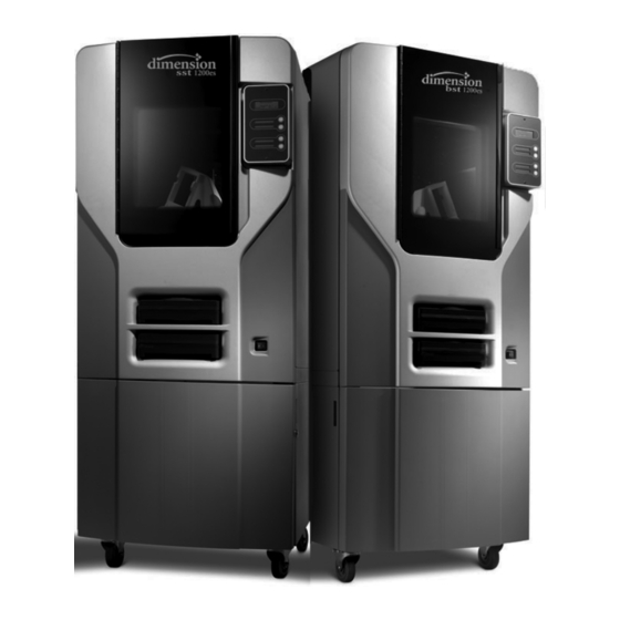
- Page 1 Dimension BST/SST 1200es ® 3D Printer User Guide 204398-0010...
-
Page 2: Legal Notice
The only warranties for Stratasys products and © 2013 Stratasys Inc. All rights reserved. services are set forth in the express warranty Stratasys, Dimension, uPrint, Catalyst, FDM, statement accompanying such products and Dimension BST, Dimension SST, WaveWash, services. Nothing herein should be construed and Ecoworks are registered trademarks of as constituting an additional warranty. -
Page 3: Table Of Contents
Table of Contents 1 Introduction..........................1 How To Use This Manual ..................2 Learn More!......................2 Recycling .......................2 Safety precautions ....................2 2 Overview ..........................4 3 Setup ............................9 Unpacking......................9 Installing Forklift Access Covers................11 Networking the printer ...................12 Power Connections....................13 Powering On ......................14 Installing software....................15 Establishing network communication with the printer ..........16 Installing System Software on printer................19 Insert Modeling Base .....................20... - Page 4 Powering Off ......................33 Removing a Completed Part..................33 Removing Support Material ..................34 5 Maintenance ...........................35 Startup Kit Tools ....................35 Daily ........................35 Clean fan filter ......................38 Replace the tip wipe assembly ................38 Tip shield replacement ...................40 Liquefier Tip Replacement ..................44 Chamber Light Bar ....................49 6 Troubleshooting ........................50 Troubleshooting Checklist ..................50 Fault determination codes..................51...
-
Page 5: Introduction
Introduction Dimension 1200es printers are designed with ultimate simplicity in mind. The systems enable you to build parts quickly, even if you have never used a 3D printer before. The systems model with ABSplus™ plastic, so modeled parts are strong and durable. ABSplus also ensures that you will be able to drill, tap, sand, and paint your creations. -
Page 6: How To Use This Manual
How To Use This Manual This User’s Guide is laid out in easy to follow sections which cover Set-up, Operation, Maintenance, and Troubleshooting. Be sure to read each section carefully so that you will get the best performance from your system. Throughout this User Guide, text representing Interface Messages that appear on the display panel are presented in a bold font. - Page 7 The following classifications are used throughout this guide. CAUTION: Indicates a potentially hazardous situation which, if not avoided, may result in minor or moderate injury. WARNING: Indicates a potentially hazardous situation which, if not avoided, could result in serious injury. Hot Surface: The hot surface sign indicates the presence of devices with high tem- peratures.
-
Page 8: Overview
The Dimension 1200es systems consist of two primary components — the Dimension 1200es 3D printer and CatalystEX. CatalystEX is the preprocessing software that runs on a Windows Vista or Windows 7 platform. - Page 9 Figure 1: Front view Extrusion Head Display Panel Extrusion Tips Tip Cleaning Assembly Guide Rods Purge Container Lead Screw Z stage platen Modeling Base Modeling Base Retainers (2) Model Material Cartridge Power Switch Support Material Cartridge...
- Page 10 Figure 2: Rear view Fan Cover UPS Connection Main Circuit Breaker Diagnostic Hookup Power Cord Adapter Network Cable Connection...
- Page 11 Figure 3 Material cartridge Figure 4 Modeling base Modeling base CAUTION: DO NOT reuse modeling bases. If a modeling base is reused, calibration errors, poor part quality, and loss of extrusion may occur. Additional modeling bases are available from your reseller.
- Page 12 Crossover Cable (Orange) 13 10x Magnifier Loupe Network Cable (Blue) ⁄ ” T-Handle Allen wrench (red) 6a BST 1200es model and support tips ⁄ ” T-Handle Allen wrench (yellow) 6b SST 1200es model and support tips 16 Dimension 1200es User Guide CD...
-
Page 13: Setup
Setup Unpacking This section describes the recommended procedures for unpacking and preparing the printer for its first use. Unpack the printer: WARNING: The printer weighs approximately 148 kg (326 lbs). Use proper moving and lifting techniques when positioning the unit. For your convenience, there are forklift pads built into the bottom of the unit. - Page 14 Figure 6: Foam tubes isolating the extrusion head from the XY-axis frame Extrusion Head Foam tubes (4) After unpacking, inspect the printer and report any shipping damage to the carrier.
-
Page 15: Installing Forklift Access Covers
Installing Forklift Access Covers The forklift access covers can be placed over the forklift channels after the printer is placed in its final location. The covers are press-fit in the front and held in place with one screw in the rear. Align the left and right side fork lift covers with the forklift channel and slide the tabs into the slots. -
Page 16: Networking The Printer
Networking the printer There are two methods of connecting your printer to your workstation, over a network or with a direct connection to your workstation. Connecting through a network: Locate the network cable (blue) from the startup kit. Connect the network cable between the printer and the network hub. See Figure 9. -
Page 17: Power Connections
Figure 10 Connecting directly to a workstation Power Connections This section discusses the procedure for preparing all power connections for the printer. CAUTION: Before connecting power to the printer, make sure that the circuit breaker is in the off (down) position. It is located at the rear of the printer, next to the power cord attachment point. -
Page 18: Powering On
Figure 1 1 Connecting power Powering On WARNING: The build chamber and extrusion-head tip get very hot! The chamber and head tip reach temperatures of approximately 75° C (167° F) and 280° C (536° F) respectively. Personal injury can occur if proper techniques and safety materials are not used. Use the leather safety gloves provided in the Startup Kit when working inside the printer. -
Page 19: Installing Software
Turn the power switch to the on (I) position. See Figure 13. After the switch is pushed, the system boots up in three to seven minutes. Note: If the printer was off and is at room temperature, it requires approximately 40 minutes to warm up before you can perform any functions. -
Page 20: Establishing Network Communication With The Printer
Installing system software to the workstation: Insert the Controller Software CD into the CD drive of your workstation. Click the Install button to load system software to your workstation. You will be asked to load this system software to your printer later. Follow prompts to finish installing system software on the workstation. - Page 21 Establishing communication on a static network: If you are using a static network or connecting the printer directly to a workstation, you will need to enter the static IP address information into the workstation and the printer. If you are using a static network and your computer already has network access, see “Setting the static network on printer:”...
- Page 22 Setting the static network on printer: Obtain your static network address from your Network Administrator. From Idle (or Ready to Build), press Maintenance on the display panel. The display will show Maintenance and the software version. Press System. Press Set Network. The top window displays: Network Admin - Static IP Address; UDN. Press Static IP to display default settings.
-
Page 23: Installing System Software On Printer
Select your printer from the drop down list then click the Update Software button. Navigate CatalystEX to the directory where the system software file is located and select the SST1200es.upg file for SST 1200es or BST1200es.upg for BST 1200es. system software will now begin to download to the printer. -
Page 24: Insert Modeling Base
Insert Modeling Base Make sure retainers are turned ‘down’ - so as not to interfere with the modeling base installation. Set the modeling base on the Z Stage Platen aligning the tabs on the modeling base with the slots on the metal tray. Slide the modeling base toward the back of the unit until its front edge (with the handle) is flush with the front edge of the tray, see Figure 14. -
Page 25: Operation
Operation Display Panel and Keypad The main User Interface to the printer is the Display Panel and Keypad, see Figure 15. Figure 15: Display panel and keypad Display Panel Keypad buttons Context-sensitive displays The display panel and keypad are very easy to use, consisting of a larger multiple-line LCD display on top, and four single-line context-sensitive displays, each with one button (or key) below. -
Page 26: System Software Overview
System software overview • Idle: If there is no part being built and no part in the build queue, the display will show that the printer is Idle. • Wait for Part or Start Part: If the printer is in Idle and the build queue is empty, you can set it to wait for a part. -
Page 27: Catalystex Overview
CatalystEX overview • General tab: This section is where you can select the model fill style, support style, change the STL units and STL scale. • Orientation tab: This section allows you to rotate, resize and auto-orient your parts. You can also change the view and insert a pause. -
Page 28: Processing Your Stl File For Printing
Processing your STL file for printing Opening your STL file with CatalystEX: Create an STL file using your CAD software. Refer to your CAD software help section for more information about converting your CAD drawings into STL files. Open the CatalystEX. From the File menu select Open STL... - Page 29 Selecting the scale of your STL file: Before you process a part for printing, you can change the size of the part within the build envelope. Every part has a pre-defined size within the STL file. After you have opened the file you can change the size of the part produced from the STL file by changing the scale.
-
Page 30: Inserting A Modeling Base
Adding your STL file to the pack: The Add to Pack button is found on the General, Orientation and Pack tabs. When you click on the Add to Pack button, CatalystEX will add the file that is currently in the preview window (General tab or Orientation tab) to the pack preview window (Pack tab). -
Page 31: Loading Material
Starting a build from the display panel: If Wait for Part has not been activated, you can send the part to the printer and start the part from the display panel after the part has been sent to the printer. From your CatalystEX workstation, send a part to the printer. - Page 32 Find the end of the material filament taped with a “flag”. CAUTION: Be careful when touching the pinch roller on the side of the cartridge. If you roll it backwards, you could draw the material into the cartridge, see Figure 19. for the correct direction to move the cartridge roller.
- Page 33 Figure 20: Snipping the material filament If the printer is in Idle, press the Material... button, which will be blinking. Display will prompt with Material - Add/Remove (flashing) Insert material cartridges into their appropriate slot from the front of the printer (Model material cartridge goes in the Top slot;...
-
Page 34: Unloading Material
Unloading Material The model and support material cartridges may be replaced separately or at the same time. In idle-, load-, or build-related modes, the panel displays the percentage of material remaining in the cartridges. If the printer will be operating unattended for a long period, and the material level is getting low, you may want to replace the cartridges before starting a new part. -
Page 35: Building A Test Part
Building a Test Part Factory test parts have been preloaded into your printer. To familiarize yourself with the system, it is recommended that you build one of the test parts before attempting to build one of your own files. Once the printer has warmed up, material has been loaded, and a modeling base is in place, you can send a test part to the printer. -
Page 36: Resuming Build From Pause Mode
Resuming Build from Pause Mode If you have pressed Pause, and are ready to resume building the part, press Resume. The printer resumes modeling. Resuming Operations from Standby Mode After several minutes of inactivity, the printer enters Standby mode. During Standby, the head temperature will decrease to save energy. -
Page 37: Powering Off
Cancelling auto power down: Turn the power switch back to the ON position. Powering Off To power-off Dimension, move the power switch to the OFF position, see Figure 13 on page 15. You can do this at any time without harming the printer. No other steps are necessary. If this is done while the printer is building a part, the current build will be lost. -
Page 38: Removing Support Material
When removing soluble supports with the soluble concentrate, wear RUBBER gloves. Dimension SST 1200es uses soluble supports - a water-based solution designed to allow you to simply wash away the support material. Your part is left smooth and clean with the fine details intact. -
Page 39: Maintenance
Maintenance Follow the simple procedures within this chapter to ensure continued proper operation of the printer. Startup Kit Tools The Startup Kit contains replacement parts and a set of tools used to help you maintain the system. The following is a list of the tools contained in the Startup Kit. •... - Page 40 Clean door The door glass can be cleaned with any commercial glass cleaner. Empty the purge container The plastic purge container is attached to the right side of the modeling envelope rear wall, see Figure 22 Note: A full purge container may impact part quality. Remove the purge container by grasping it and pushing it upward to release it from its three mounts.
- Page 41 Preventive Maintenance Alerts will be displayed on the workstation at the 500 hour time interval as a reminder to perform preventive maintenance. See Figure 23 for SST 1200es and Figure 24 BST 1200es. Figure 23 SST 1200es Preventive Maintenance Alert Figure 24 BST 1200es Preventive Maintenance Alert...
-
Page 42: Clean Fan Filter
Clean fan filter To clean the fan filter: Locate the lower fan on the rear panel of the printer and remove the plastic frame (snaps on and off) that secures the fan filter. See Figure 25 Figure 25: Lower fan location Clean the filter with soap and water, and blot it dry. - Page 43 Figure 26: Move the Toggle Head to the left Remove the tip wipe assembly by lifting the assembly up and out of the machine. Discard the old tip wipe assembly, see Figure 26 Figure 27: Replacing the tip wipe assembly Tip wipe assembly Place the new tip wipe assembly over the two mounting posts making sure the assembly is fully...
-
Page 44: Tip Shield Replacement
Tip shield replacement Tip shields can become torn or damaged over time. This can have a negative impact on the surface finish and detail of models. Figure 28: Tip shield damage New shield Worn shield Enter Head Maintenance. From the display panel press Maintenance. Press Machine. - Page 45 Position the blade of a small screwdriver between the tip shield and tip plate. Use the blade of the small screwdriver to separate the tip shroud from the tip plate. See Figure 30. Figure 30 Tip shield removal Insert small standard Tip plate screwdriver to pry tip Tip shield...
- Page 46 Figure 32 Tip shield installation Figure 33: Tip shield placement Tip shield NOT seated correctly Tip shield seated correctly Replace head cover. Note: If the head cover is not replaced the printer may not function properly. Exit Maintenance, press Done until back at Idle.
- Page 47 Preventive Maintenance Alerts will be displayed on the workstation at the 2000 hour time interval as a reminder to perform preventive maintenance. See Figure 34 for SST 1200es and Figure 35 for BST 1200es. Figure 34 SST 1200es Preventive Maintenance Alert Figure 35 BST 1200es Preventive Maintenance Alert...
-
Page 48: Liquefier Tip Replacement
Liquefier Tip Replacement Replace Tips at approximately 2000 hours - depending upon operating conditions. Tips can also be damaged by improper care while performing maintenance in the area around the tips. Note: CatalystEX displays the tip time (hrs) - from the Printer Services Tab - Printer Info button (Tip time will reset to zero after replacement). - Page 49 (The tips come in a Red capped container). For a Dimension SST 1200es, you must identify the correct replacement tip. The SST 1200es uses two tip types. You must make sure a SUPPORT tip is used on the LEFT side of the head assembly.
- Page 50 Figure 39: Identifying Tips Liquefier tube Longer tube Flared inlet Shorter tube No flare Imprinted with “Soluble” With gloved hand, insert the new tip into the heater block. Use needle nose pliers to grasp the stainless steel shield of the tip. Pull the tip shield toward you, then lift up to install the tip.
- Page 51 Install a new tip shield by pushing it over the exposed tip, keeping the slotted end toward the back of the head. See Figure 41 NOTE: Tip shield should be flush with the tip plate as shown in Figure 42. Figure 41: Tip shield installation Figure 42:...
- Page 52 After Material Loading is complete the printer will display Tip Calibration - Install Modeling Base And Build Calibration Part. CAUTION: Make sure a NEW, UNUSED modeling base is installed before starting calibration. Calibration results will be incorrect if a NEW, UNUSED modeling base is not used.
-
Page 53: Chamber Light Bar
Select Done after you have input the X and Y offsets. The printer will return to Maintenance. Run the XY calibration a second time to be sure the values changed the offset properly. When finished, press Done until back at Idle. As Needed Maintenance The following maintenance items have no routine schedule but should be tended to as needed. -
Page 54: Troubleshooting
Troubleshooting Troubleshooting Checklist Problem or error message Solution Verify power cord is securely plugged in. No power Verify that the circuit breaker (at rear of system) and the power switch (on front panel of system) are both in the ON position. Verify AC power is present at wall outlet. -
Page 55: Fault Determination Codes
Problem or error message Solution Verify a modeling base is inserted. Display Panel displays Modeling base may be used or defective – replace. Can’t Find Home – Check Modeling Base Display Panel displays The system stopped reporting its status at the Universal Coordinated Time (UCT) shown. -
Page 56: Cycling Power
Cycling power Turn the power switch to the OFF position. The display will show Shutting Down. After the printer has cooled down enough to shut down, the display will go blank. When the display is blank and the printer has shut down, turn the circuit breaker to the OFF position. -
Page 57: Clogged Tip
Display will ask Which Materials Loaded? Press Both. Press Done until back at Idle. Clogged tip Occasionally, a tip may clog with material. This will often result in a loss of extrusion (LOE). A clogged tip will prohibit material load and part building. Remove the head cover by pressing the tabs in and pulling away from the head. -
Page 58: Material Jam
Replace head cover. Note: If the head cover is not replaced the printer may not function properly. 1 1. Display will ask Which Materials Loaded? Press Model if only model material is loaded, press Support if only support material is loaded or press Both if both model and support material are still loaded. - Page 59 Figure 46: Tip inlet locations Support tip inlet Model tip inlet Press Select Drive and choose the drive that may have the clogged tip. Press Forward, the drive wheel will turn the selected drive forward. Press Blower Off, this will turn the head cooling fan off for 10 seconds, allowing the tip to heat up beyond operating temperature.
-
Page 60: Recovering From Loss Of Extrusion
Recovering from loss of extrusion Note: It is recommended that you read and understand this entire procedure before performing any of the work. Enter Head Maintenance mode. From Idle, press Maintenance. Press Machine. Press Head. The head will heat up to operating temperature which will take approximately 3 minutes. - Page 61 Figure 48: Head Components Toggle spring Drive wheel Support side idler wheel Model side idler wheel Toggle bar Figure 49: Toggle bar in neutral position Remove any excess material found around the head area. Note: Material fed to the tip can sometimes jam causing a build-up of material under the head cover.
- Page 62 For easier access to areas that may need to be cleaned, move the material idler wheels out of the way (there is one idler wheel for support material and one for model material, Figure 48.) Note: Move only one idler wheel assembly at a time. Finish cleaning around the moved wheel and restore it to its normal position before moving the other idler wheel.
- Page 63 Figure 51: Holding access space open - model side shown Insert 1/8 inch T- Handle into fixture hole. Ease pressure on the ⁄ ” T-Handle Allen wrench to carefully return the leveraged idler wheel back toward its original position - until the idler assembly is resting against the ⁄...
-
Page 64: Support
Support Customer Support Contact your local reseller for technical support. When contacting your reseller please provide the following: • Your name. • Your telephone number. • System model. • System serial number. • System software build number. • CatalystEX version number. •... -
Page 65: Recycling
Recycling Visit http://www.stratasys.com/recycle for recycling information on material cartridges. Figure 52 Recycling Codes System Component Materials Recycling Code Modeling bases All packaging materials can be recycled per your local recycling guidelines. -
Page 66: Printer Specifications
Printer Specifications Physical specifications Height 1 143 mm (45 in) Width 737 mm (29 in) Depth 838 mm (33 in) Weight 148 kg (326 lbs) Facility specifications Installation location Stable flat surface capable of holding 159 kg (350 lbs). Power Requirements 100–240VAC ~ 12 - 7A 50/60Hz 1200W dedicated circuit within 2 m (80 in.) Do not use an extension cord or a power strip, using these can possibly cause intermittent power issues. -
Page 67: Workstation Specifications
Workstation specifications Operating System Microsoft Windows Vista or Microsoft Windows 7 Processor Minimum: 2.4 GHz Faster processors will shorten job processing times Minimum: 1GB (2GB for Windows Vista or Windows 7) Recommended: 2GB (3GB for Windows Vista or Windows 7) Hard Disk Installation: 90MB Monitor graphics reso-... -
Page 68: 10 Supplemental Information
10 Supplemental Information Stratasys Limited Warranty Statement A copy of the warranty is available upon request from info@stratasys.com. Declaration of Conformity... -
Page 69: Regulatory And Environmental Information
Regulatory and environmental information EMC Class A Warning WARNING: This is a Class A product. In a domestic environment this product may cause radio interference in which case the user may be required to take adequate measures. FCC Statements (U.S.A.) The U.S. - Page 70 Disposal of waste equipment by users in private households in the European Union This symbol on the product or on its packaging indicates that this product must not be disposed of with your other household waste. Instead, it is your responsibility to dispose of your waste equipment by handing it over to a designated collection point for the recycling of waste electrical and electronic equipment.
-
Page 71: Appendix
Uninterruptible Power Supply (UPS) Use and Installation The intent of the Uninterruptible Power Supply (UPS) shutdown feature on Dimension and uPrint 3D printers is to prevent required maintenance and/or system damage by safely shutting the system down in the event of an uncontrolled loss of power. Whether an in-process build of a part will complete successfully is dependent on the battery life of the selected UPS and the duration of the power outage. - Page 72 Figure 53: Wired-And configuration Parts List – Cable, UPS to 3D Printer Item Nomenclature / Description Material Specification Conn, Hsg, Plug, 9Pos AMP - 205204-9 Pin, Male, 24-20 AWG AMP - 1-66506-0 Shell, Size 1, 9-Pin w/Grommets AMP - 748677- 1 Jackscrew Pair 4-40, Knurled AMP - 747784-3 XX.x...
- Page 73 Figure 54: UPS Cable Diagram...
Need help?
Do you have a question about the BST 1200es and is the answer not in the manual?
Questions and answers