
Related Manuals for Kyocera FS-1030MPF


Summary of Contents for Kyocera FS-1030MPF
-
Page 1: Service Manual
FS-1030MPF////// FS-1030MFP/DP FS-1035MFP/DP FS-1130MFP////// FS-1135MFP////// SERVICE MANUAL Published in May 2012 2MHSM062 Rev.2... - Page 2 CAUTION RISK OF EXPLOSION IF BATTERY IS REPLACED BY AN INCORRECT TYPE. DISPOSE OF USED BATTERIES ACCORDING TO THE INSTRUCTIONS. It may be illegal to dispose of this battery into the municipal waste stream. Check with your local solid waste officials for details in your area for proper disposal. ATTENTION IL Y A UN RISQUE D’EXPLOSION SI LA BATTERIE EST REMPLACEE PAR UN MODELE DE TYPE INCORRECT.
- Page 3 Revision history Revision Date Replaced pages Remarks 24 April 2012 Contents, 1-1-2, 1-1-3, 1-3-21, 2-4-13 to 20, Address - 25 May 2012 Contents, 1-4-2 to 6...
- Page 4 This page is intentionally left blank.
-
Page 5: Safety Precautions
Safety precautions This booklet provides safety warnings and precautions for our service personnel to ensure the safety of their customers, their machines as well as themselves during maintenance activities. Service personnel are advised to read this booklet carefully to familiarize themselves with the warnings and precautions described here before engaging in maintenance activities. - Page 6 Safety warnings and precautions Various symbols are used to protect our service personnel and customers from physical danger and to prevent damage to their property. These symbols are described below: DANGER: High risk of serious bodily injury or death may result from insufficient attention to or incorrect compliance with warning messages using this symbol.
-
Page 7: Installation Precautions
1. Installation Precautions WARNING • Do not use a power supply with a voltage other than that specified. Avoid multiple connections to one outlet: they may cause fire or electric shock. When using an extension cable, always check that it is adequate for the rated current...................... •... - Page 8 2. Precautions for Maintenance WARNING • Always remove the power plug from the wall outlet before starting machine disassembly....• Always follow the procedures for maintenance described in the service manual and other related brochures............................• Under no circumstances attempt to bypass or disable safety features including safety mechanisms and protective circuits.
- Page 9 • Do not remove the ozone filter, if any, from the copier except for routine replacement....... • Do not pull on the AC power cord or connector wires on high-voltage components when removing them; always hold the plug itself......................•...
- Page 10 This page is intentionally left blank.
-
Page 11: Table Of Contents
2MH/2MJ/2MK/2ML-2 CONTENTS 1-1 Specifications 1-1-1 Specifications ........................1-1-1 1-1-2 Parts names .......................... 1-1-6 (1) Overall ..........................1-1-6 (2) Operation panel ........................ 1-1-7 (3) Option ..........................1-1-8 1-1-3 Machine cross section ......................1-1-9 1-2 Installation 1-2-1 Installation environment......................1-2-1 1-2-2 Unpacking..........................1-2-2 (1) Unpacking......................... - Page 12 (1) Precautions........................1-5-1 (2) Drum unit .......................... 1-5-1 (3) Toner ..........................1-5-1 (4) How to tell a genuine Kyocera Mita toner container ............1-5-2 1-5-2 Outer covers .......................... 1-5-3 (1) Detaching and refitting the left cover and right cover ............1-5-3 1-5-3 Paper feed section.........................
- Page 13 2MH/2MJ/2MK/2ML 1-5-10 Others ..........................1-5-49 (1) Detaching and refitting the main motor................1-5-49 (2) Direction of installing the left cooling fan motor, right cooling fan motor and power source fan motor ...................... 1-5-50 1-5-11 Document processor ......................1-5-51 (1) Detaching and refitting the DP rear cover and DP front cover ........1-5-51 (2) Detaching and refitting the DP drive PWB..............
- Page 14 2MH/2MJ/2MK/2ML-1 2-4 Appendixes 2-4-1 Appendixes ..........................2-4-1 (1) Wiring diagram ......................... 2-4-1 (2) Repetitive defects gauge ....................2-4-3 (3) Maintenance parts list....................... 2-4-4 (4) Firmware Environment Commands .................. 2-4-5 (5) Maintenance Commands....................2-4-13 INSTALLATION GUIDE PAPER FEEDER...
-
Page 15: Specifications
2MH/2MJ/2MK/2ML 1-1 Specifications 1-1-1 Specifications Machine Specifications Item 3 in 1 model (without FAX) 4 in 1 model (with FAX) 30ppm 35ppm 30ppm 35ppm Desktop Type Electrophotography by semiconductor laser, single drum system Printing method Sheet, Book, 3-dimensional objects (maximum original size: Folio/Legal) Originals Fixed Original feed system... - Page 16 2MH/2MJ/2MK/2ML-1 Specifications Item 3 in 1 model (without FAX) 4 in 1 model (with FAX) 30ppm 35ppm 30ppm 35ppm 150 sheets (80g/m Output tray capacity 1 to 999 sheets Continuous copying Exposure lamp (LED) Light source Flat bed scanning by CCD image sensor Scanning system OPC drum (diameter 30 mm) Photoconductor...
- Page 17 2MH/2MJ/2MK/2ML-1 Specifications Item 3 in 1 model (without FAX) 4 in 1 model (with FAX) 30ppm 35ppm 30ppm 35ppm 120 V AC, 60 Hz, more than 10.0 A Power source 220 - 240 V AC, 50/60 Hz, more than 6.0 A Paper feeder ×...
- Page 18 2MH/2MJ/2MK/2ML Scanner Item Specifications Windows 2000 (Service Pack 4), Windows XP, Windows Vista, Operating system Windows 7, Windows Server 2003, Windows Server 2008 600 dpi, 400 dpi, 300 dpi, 200 dpi, 200 × 400 dpi, 200 × 100 dpi Resolution JPEG, TIFF, PDF, XPS File format B/W : 35 images/min...
- Page 19 2MH/2MJ/2MK/2ML FAX (4 in 1 model (with FAX) only) Item Specifications Super G3 Compatibility Subscriber telephone line Communication line 3 s or less (33600 bps, JBIG, ITU-T A4 #1 chart) Transmission time 33600/31200/28800/26400/24000/21600/19200/16800/14400/12000/9600/ Transmission speed 7200/4800/2400 bps JBIG/MMR/MR/MH Coding scheme Error correction A4, B5(JIS), A5, Legal, Letter, Statement, Oficio II, 216x340 Original size...
-
Page 20: Parts Names
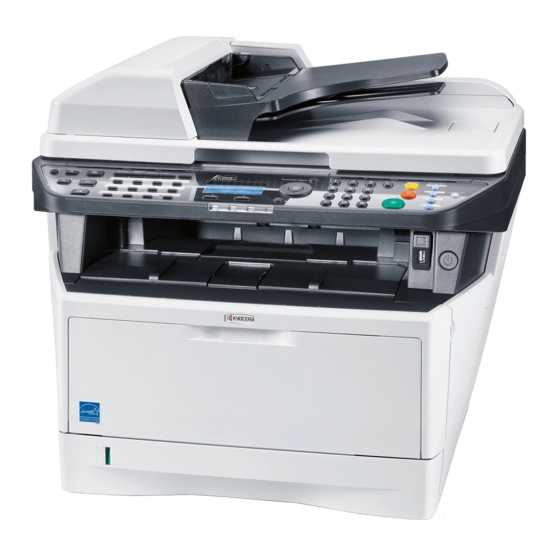
2MH/2MJ/2MK/2ML 1-1-2 Parts names (1) Overall Figure 1-1-1 1. Platen (contact glass) 12. Paper stopper 23. Power switch 2. Original size Indicator plate 13. Paper width guides 24. Power cord connector 3. Operation panel 14. Cassette 25. Top cover 26. Original width guides *2 4. - Page 21 2MH/2MJ/2MK/2ML (2) Operation panel 12 13 15 16 17 18 27 28 29 30 Figure 1-1-2 1. System menu/Counter key 11. Document Box key (LED) 22. Reset key (LED) 12. FAX key (LED) * 23. Attention indicator 2. Status/Job Cancel key (LED) 13.
- Page 22 2MH/2MJ/2MK/2ML (3) Option System Kit Expention memory: for copy and printer General-purpose 144pin DIMM (1 slot) Card Authentication Kit(B) Network interface Kit IB-23 * 3in1 model only Figure 1-1-3 1. Machine 2. Paper feeder 1-1-8...
-
Page 23: Machine Cross Section
2MH/2MJ/2MK/2ML 1-1-3 Machine cross section Paper path Paper path (option) Light path Figure 1-1-4 1. Cassette 8. Laser scanner unit (LSU) 2. MP tray 9. Transfer/separation section 3. Paper feed/conveying section 10. Fuser section 4. Toner container 11. Exit section 5. - Page 24 2MH/2MJ/2MK/2ML Original path Light path Figure 1-1-5 14. Image scanner unit (ISU) 15. Document processor (DP) * * : Only model with Document Processor as standard 1-1-10...
- Page 25 2MH/2MJ/2MK/2ML This page is intentionally left blank. 1-1-11...
-
Page 26: Installation Environment
2MH/2MJ/2MK/2ML 1-2 Installation 1-2-1 Installation environment 1. Temperature: 10 to 32.5C/50 to 90.5F 2. Humidity: 15 to 80%RH 3. Power supply: 120 V AC, 7.8 A 220 - 240 V AC, 4.0 A 4. Power source frequency: 50 Hz 0.3%/60 Hz 0.3% 5. -
Page 27: Unpacking
2MH/2MJ/2MK/2ML 1-2-2 Unpacking (1) Unpacking 120 V AC model 220-240 V AC model Figure 1-2-2 21. Safety guide 1 1. Machine 11. Plastic bag 2. Outer case 12. Power cord 22. Safety guide 2 3. Inner frame 13. Plastic bag (250 ´ 600) 23. -
Page 28: Removing The Tapes
2MH/2MJ/2MK/2ML (2) Removing the tapes <Procedure> 1. Remove two tapes. 2. Open the sheet. Sheet Tape Tape Sheet Figure 1-2-3 3. Remove two tapes A. Tape A 4. Open the top cover. Top cover 5. Remove the tape B and then remove the spacer. - Page 29 2MH/2MJ/2MK/2ML 7. Remove two tapes. Tape Tape Figure 1-2-5 8. Open the DP. 9. Remove the sheet. 10. Remove the paper. Sheet Paper Figure 1-2-6 1-2-4...
- Page 30 2MH/2MJ/2MK/2ML 11. Remove the tape A. 12. Move the lock lever to the position of Tape A release. * : When turning on power if the lock lever is not released, the error message is displayed. 13. Close the DP. 14.
-
Page 31: Installing The Expansion Memory (Option)
2MH/2MJ/2MK/2ML 1-2-3 Installing the expansion memory (option) <Procedure> 1. Turn off the power switch and pull out the power cable. Caution: Do not insert or remove expansion memory while machine power is on. Doing so may cause damage to the machine and the expansion memory. -
Page 32: Maintenance Mode
2MH/2MJ/2MK/2ML 1-3 Maintenance Mode 1-3-1 Maintenance mode The machine is equipped with a maintenance function which can be used to maintain and service the machine. (1) Executing a maintenance item Start Enter “10871087” using Maintenance mode is entered. the numeric keys. Enter the maintenance item The maintenance item is selected. -
Page 33: Maintenance Modes Item List
2MH/2MJ/2MK/2ML (2) Maintenance modes item list Item Initial Section Content of maintenance item setting General U000 Outputting an maintenance report U002 Setting the factory default data U004 Setting the machine number Operation U203 Checking DP operation panel and U222 Setting the IC card type Other support equipment... - Page 34 2MH/2MJ/2MK/2ML Item Initial Section Content of maintenance item setting U620 Setting the remote switching mode U625 Setting the transmission system 1 Setting the auto redialing interval 3 (120 V) 2 (220-240 V) Setting the number of times of auto redialing 2 (120 V) 3 (220-240 V) U630...
- Page 35 2MH/2MJ/2MK/2ML Item Initial Section Content of maintenance item setting U651 Setting modem 2 Modem output level 9 (120 V) 10 (220-240 V) DTMF output level (main value) 5 (120 V) 10.5 (220-240 V) DTMF output level (level difference) 2 (120 V) 2.5 (220-240 V) U660 Setting the NCU...
-
Page 36: Contents Of The Maintenance Mode Items
2MH/2MJ/2MK/2ML (3) Contents of the maintenance mode items Item No. Description U000 Outputting an maintenance report Description Outputs lists of the current settings of the maintenance items and paper jam and service call occurrences. Outputs the event log. Also sends output data to the USB memory. Printing a report is disabled either when a job is remaining in the buffer or when [Pause All Print Jobs] is pressed to halt printing. -
Page 37: Event Log
2MH/2MJ/2MK/2ML Item No. Description U000 Event log Event Log 06/Apr/2010 08:40 Firmware Version 2MH_2000.000.000 2010.04.06 [XXXXXXXX] [XXXXXXXX] [XXXXXXXX] Paper Jam Log Service Call Log Count. Event Descriprions Count. Service Code 1876543 1000.01.08.01.01 1881214 01.0030 166554 1000.01.08.01.02 178944 01.1010 4988 1000.01.08.01.01 5296 01.4000 4988... - Page 38 2MH/2MJ/2MK/2ML Item No. Description U000 Detail of event log Items Description System version System date Engine soft version Engine boot version Operation panel mask version Machine serial number Paper Jam Count. Event Remembers 1 to 16 of The total page count Log code (2 digit, hexa- occurrence.
- Page 39 2MH/2MJ/2MK/2ML Item No. Description U000 Items Description Paper Jam 4208: Eject sensor non arrival jam (duplex) cont. 4209: Eject sensor non arrival jam (Mp tray) 4211: Eject sensor stay jam (cassette 1) 4212: Eject sensor stay jam (cassette 2) 4213: Eject sensor stay jam (cassette 3) 4218: Eject sensor stay jam (duplex) 4219: Eject sensor stay jam (MP tray) 4220: Eject sensor initial jam (Warm up)
- Page 40 2MH/2MJ/2MK/2ML Item No. Description U000 Items Description Paper Jam (c) Detail of paper size (Hexadecimal) cont. 00: (Not specified) 0B: B4 22: Special 1 01: Monarch 0C: Ledger 23: Special 2 02: Business 0D: A5R 24: A3 wide 03: International DL 0E: A6 25: Ledger wide 26: Full bleed paper...
- Page 41 2MH/2MJ/2MK/2ML Item No. Description U000 Items Description Maintenance Count. Item Remembers 1 to 8 of The total page count Code of mainte- occurrence of at the time of the nance replacing item replacement. If the replacement of the (1 byte, 2 categories) occurrence of the toner container.
- Page 42 2MH/2MJ/2MK/2ML Item No. Description U002 Setting the factory default data Description Restores the machine conditions to the factory default settings. Purpose To move the image scanner unit to the home position. (position in which the frame can be fixed). Method 1.
- Page 43 2MH/2MJ/2MK/2ML Item No. Description U203 Checking DP operation Description Simulates the original conveying operation separately in the DP. Purpose To check the DP operation. Method 1. Press the start key. 2. Place an original in the DP if running this simulation with paper. 3.
- Page 44 2MH/2MJ/2MK/2ML Item No. Description U222 Setting the IC card type Description Sets the type of IC card. Purpose To change the type of IC card. Setting 1. Press the start key. 2. Select the item using the cursor up/down keys. Display Description OTHER...
- Page 45 2MH/2MJ/2MK/2ML Item No. Description U251 Checking/clearing the maintenance count Description Displays, clears and changes the maintenance count. Purpose To check the maintenance count. Also to clear the count during maintenance service (replacing the maintenance kit). Method 1. Press the start key. The maintenance count is displayed. Setting 1.
- Page 46 2MH/2MJ/2MK/2ML Item No. Description U252 Setting the destination Description Switches the operations and screens of the machine according to the destination. Purpose To be executed after initializing the backup RAM, in order to return the setting to the value before replacement or initialization.
- Page 47 2MH/2MJ/2MK/2ML Item No. Description U260 Selecting the timing for copy counting Description Changes the copy count timing for the total counter and other counters. Purpose To be set according to user request. Setting 1. Press the start key. 2. Select the copy count timing using the cursor up/down keys. Display Description FEED...
- Page 48 2MH/2MJ/2MK/2ML Item No. Description U332 Setting the size conversion factor Description Sets the coefficient of nonstandard sizes in relation to the A4/Letter size. The coefficient set here is used to convert the black ratio in relation to the A4/Letter size and to display the result in user simulation.
- Page 49 2MH/2MJ/2MK/2ML Item No. Description U411 Adjusting the scanner automatically Description Uses a specified original and automatically adjusts the following items in the scanner and the DP scanning sections. Scanner section: Original size magnification, leading edge timing, center line, input gamma, input gamma in monochrome mode and matrix DP scanning section: Original size magnification, leading edge timing, center line Purpose...
- Page 50 2MH/2MJ/2MK/2ML Item No. Description U411 Error Codes Codes Description Black band detection error (scanner leading edge registration) Black band detection error (scanner center line) Black band detection error (scanner main scanning direction magnification) Black band is not detected (scanner leading edge registration) Black band is not detected (scanner center line) Black band is not detected (scanner main scanning direction magnification) Black band is not detected...
- Page 51 2MH/2MJ/2MK/2ML Item No. Description U425 Setting the target Description Enters the lab values that is indicated on the back of the chart (P/N: 302FZ56990) used for adjustment. Purpose Performs data input in order to correct for differences in originals during automatic adjustment. Method 1.
- Page 52 2MH/2MJ/2MK/2ML-1 Item No. Description U425 Setting: [ADJUST ORIGINAL] 1. Measure the distance from the left edge to the black belt (a) of the original at A, B and C. Measurement procedure 1) Measure the distance from the edge to the black belt (a) of the original at A (30 mm from the leading edge), B (154.5 mm from the leading edge) and C (267 mm from the leading edge), respectively.
- Page 53 2MH/2MJ/2MK/2ML Item No. Description U600 Initializing all data Description Initializes software switches and all data in the backup data on the FAX control PWB, according to the destination and OEM. Executes the check of the file system, when abnormality of the file system is detected, initializes the file system, communication past record and register setting contents.
- Page 54 2MH/2MJ/2MK/2ML Item No. Description U601 Initializing permanent data Description Initializes software switches on the FAX control PWB according to the destination and OEM. Purpose To initialize the FAX control PWB without changing user registration data. Method 1. Press the start key. 2.
- Page 55 2MH/2MJ/2MK/2ML Item No. Description U604 Setting user data 2 Description Makes user settings to enable the use of the machine as a fax. Purpose Use this if the user wishes to adjust the number of rings that occur before the unit switches into fax receiving mode when fax/telephone auto-select is enabled.
- Page 56 2MH/2MJ/2MK/2ML Item No. Description U610 Setting system 1 Description Makes settings for fax reception regarding the sizes of the fax paper and received images and automatic printing of the protocol list. Method 1. Press the start key. 2. Select the item to be set using the cursor up/down keys. Display Description CUT LINE:100%...
- Page 57 2MH/2MJ/2MK/2ML Item No. Description U610 Setting the number of lines to be ignored when receiving a fax (A4R/LetterR) in the auto reduction mode Sets the maximum number of lines to be ignored if the received data volume exceeds the record- ing capacity when the data is recorded in the auto reduction mode onto A4R or LetterR paper under the conditions below.
- Page 58 2MH/2MJ/2MK/2ML Item No. Description U611 Setting system 2 Description Sets the number of adjustment lines for automatic reduction. Method 1. Press the start key. 2. Select the item to be set using the cursor up/down keys. Display Description ADJ LINES Sets the number of adjustment lines for automatic reduction.
- Page 59 2MH/2MJ/2MK/2ML Item No. Description U612 Setting system 3 Description Makes settings for fax transmission regarding operation and automatic printing of the protocol list. Method 1. Press the start key. 2. Select the item to be set using the cursor up/down keys. Display Description AUTO REDUCTION...
- Page 60 2MH/2MJ/2MK/2ML Item No. Description U612 Selecting if detection of trail edge margin is to be performed This determines whether trailing edge margin is detected (to prevent image from being mutilated) while printing a received Fax. 1. Select the setting using the cursor left/right keys. Display Description The trail edge margin is detected.
- Page 61 2MH/2MJ/2MK/2ML Item No. Description U625 Setting the transmission system 1 Description Makes settings for the auto redialing interval and the number of times of auto redialing. Purpose Change the setting to prevent the following problems: fax transmission is not possible due to too short redial interval, or fax transmission takes too much time to complete due to too long redial interval.
- Page 62 2MH/2MJ/2MK/2ML Item No. Description U630 Setting communication control 1 Description Makes settings for fax transmission regarding the communication. Method 1. Press the start key. 2. Select the item to be set using the cursor up/down keys. Display Description TX SPEED Sets the communication starting speed.
- Page 63 2MH/2MJ/2MK/2ML Item No. Description U630 Setting the reception speed Sets the reception speed that the sender is informed of using the DIS or NSF signal. When the (cont.) destination unit has V.34 capability, V.34 is selected, regardless of the setting. 1.
- Page 64 2MH/2MJ/2MK/2ML Item No. Description U631 Setting communication control 2 Description Makes settings regarding fax transmission. Method 1. Press the start key. 2. Select the item to be set using the cursor up/down keys. Display Description ECM TX Sets ECM transmission. ECM RX Sets ECM reception.
- Page 65 2MH/2MJ/2MK/2ML Item No. Description U632 Setting communication control 3 Description Makes settings for fax transmission regarding the communication. Method 1. Press the start key. 2. Select the item to be set using the cursor up/down keys. Display Description DIS 4BYTE Sets the DIS signal to 4 bytes.
- Page 66 2MH/2MJ/2MK/2ML Item No. Description U632 Setting the CNG detection times in the fax/telephone auto select mode Sets the CNG detection times in the fax/telephone auto select mode. 1. Select the setting using the cursor up/down keys. Display Description 1TIME Detects CNG once. 2TIMES Detects CNG twice.
- Page 67 2MH/2MJ/2MK/2ML Item No. Description U633 Setting the V.34 symbol speed (3429 Hz) Sets if the V.34 symbol speed 3429 Hz is used. 1. Select the setting using the cursor up/down keys. Display Description V.34 symbol speed 3429 Hz is used. V.34 symbol speed 3429 Hz is not used.
- Page 68 2MH/2MJ/2MK/2ML Item No. Description U634 Setting communication control 5 Description Sets the maximum number of error bytes judged acceptable when receiving a TCF signal. Used as a measure to ease transmission conditions if transmission errors occur. Setting 1. Press the start key. 2.
- Page 69 2MH/2MJ/2MK/2ML Item No. Description U641 Setting communication time 2 Description Sets the time-out time for fax transmission. Purpose To improve transmission performance for international communications mainly. Method 1. Press the start key. 2. Select the item to be set using the cursor up/down keys. Display Description T0 TIME OUT...
- Page 70 2MH/2MJ/2MK/2ML Item No. Description U641 Setting the T2 time-out time The T2 time-out time decides the following. From CFR signal output to image data reception From image data reception to the next signal reception In ECM, from RNR signal detection to the next signal reception 1.
- Page 71 2MH/2MJ/2MK/2ML Item No. Description U641 Setting the Tb2 time-out time In the fax/telephone auto select mode, sets the time to start ringing an operator through the con- nected telephone after receiving a call as a fax machine (see figure 1-3-3). In the fax/telephone auto select mode, change the setting when fax reception is unsuccessful or a telephone fails to receive a call.
- Page 72 2MH/2MJ/2MK/2ML Item No. Description U650 Setting modem 1 Description Sets the G3 cable equalizer. Sets the modem detection level. Purpose Perform the following adjustment to make the equalizer compatible with the line characteristics. To improve the transmission performance when a low quality line is used. Method 1.
- Page 73 2MH/2MJ/2MK/2ML Item No. Description U651 Setting modem 2 Description Sets the modem output level. Sets the DTMF output level of a push-button dial telephone. Purpose Used if problems occur when sending a signal with a push-button dial telephone. Setting 1. Press the start key. 2.
- Page 74 2MH/2MJ/2MK/2ML Item No. Description U660 Setting the NCU Description Makes setting regarding the network control unit (NCU). Purpose To be set when installing the facsimile kit. Method 1. Press the start key. 2. Select the item to be set using the cursor up/down keys. Display Description EXCHANGE...
- Page 75 2MH/2MJ/2MK/2ML Item No. Description U660 Setting busy tone detection When a fax signal is sent, sets whether the line is disconnected immediately after a busy tone is detected, or the busy tone is not detected and the line remains connected until T0 time-out time. Fax transmission may fail due to incorrect busy tone detection.
- Page 76 2MH/2MJ/2MK/2ML Item No. Description U670 Outputting lists Description Outputs a list of data regarding fax transmissions. Printing a list is disabled either when a job is remaining in the buffer or when [Pause All Print Jobs] is pressed to halt printing. Purpose To check conditions of use, settings and transmission procedures of the fax.
- Page 77 2MH/2MJ/2MK/2ML Item No. Description U695 FAX function customize Description Sets fax batch transmission ON/OFF. Also changes the print size priority at the time of small size reception. Purpose To be executed as required. Setting 1. Select the setting using the cursor up/down keys. Display Description FAX BULK TX...
- Page 78 2MH/2MJ/2MK/2ML Item No. Description U699 Setting the software switches Description Sets the software switches on the FAX control PWB individually. Purpose To change the setting when a problem such as split output of received originals occurs. Since the communication performance is largely affected, normally this setting need not be changed.
- Page 79 2MH/2MJ/2MK/2ML Item No. Description U699 <Communication time setting> Item 76543210 T3 timeout setting 76543210 T4 timeout setting (automatic equipment) 76543210 T5 timeout setting 76543210 Time before transmission of CNG (1100 Hz) signal 76543210 T0 timeout setting (manual equipment) 7 Phase C timeout in ECM reception 76543210 Timeout 1 in countermeasures against echo 76543210 Timeout for FSK detection start in V.8 <Modem setting>...
- Page 80 2MH/2MJ/2MK/2ML Item No. Description U910 Clearing the black ratio data Description Clears the accumulated black ratio data for A4 sheet. Purpose To clear data as required at times such as during maintenance service. Method 1. Press the start key. 2. Select [ALL CLEAR] using the cursor up/down keys. 3.
- Page 81 2MH/2MJ/2MK/2ML Item No. Description U917 Setting backup data reading/writing Description Retrieves the backup data to a USB memory from the machine; or writes the data from the USB memory to the machine. Purpose To store and write data when replacing the control PWB. Method 1.
- Page 82 2MH/2MJ/2MK/2ML Item No. Description U917 Error Codes Codes Description Codes Description e002 Parameter error e31e User managements error e003 File write error e31f User managements open error e004 File initialization error e320 User managements error e005 File error e410 Box file open error e006 Processing error e411...
- Page 83 2MH/2MJ/2MK/2ML Item No. Description U917 Error Codes Codes Description Codes Description d000 Unspecified error d00b File reading error d001 HDD unavailable d00c File writing error d002 USB memory is not inserted d00d File copy error d003 File for writing is not found in the USB d00e File compressed error d004...
- Page 84 2MH/2MJ/2MK/2ML Item No. Description U977 Data capture mode Description Store the print data sent to the machine into USB memory. Purpose In case to occur the error at printing, check the print data sent to the machine. Method 1. Insert USB memory in USB memory slot. 2.
-
Page 85: Service Mode
2MH/2MJ/2MK/2ML 1-3-2 Service mode The machine is equipped with a maintenance function which can be used to maintain and service the machine. (1) Executing a service mode Start Press the System Menu/Counter key. The Sys. Menu/Count. menu appears. Select [Adjust/Maint.] using the cursor The Adjust/Maint. -
Page 86: Description Of Service Mode
2MH/2MJ/2MK/2ML (2) Description of service mode Service items Description Service Status Printing a status page for service purpose Description Prints a status page for service purpose. The status page includes various settings and service cumulative. Purpose To acquire the current printing environmental parameters and cumulative information. Method 1. -
Page 87: Service Status Page
2MH/2MJ/2MK/2ML Service items Description Service status page (1) Service Status Page 30/06/2010 12:00 Firmware version 2MH_2000.000.000 2009.08.09 [XXXXXXXX] [XXXXXXXX] [XXXXXXXX] Controller Information Memory status (27) Standard Size 128.0 KB FRPO Status Option Slot 128.0 KB User Top Margin A1+A2/100 0.00 Total Size 256.0 KB User Left Margin... -
Page 88: Engine Information
2MH/2MJ/2MK/2ML Service items Description Service status page (2) Service Status Page 30/06/2010 12:00 Firmware version 2MH_2000.000.000 2009.08.09 [XXXXXXXX] [XXXXXXXX] [XXXXXXXX] Engine Information Send Information (32) (37) NVRAM Version _1F31255_1F31255 Date and Time 10/06/30 (33) (38) Scanner Version 2LX_1200.001.089 Address (34) FAX Slot1 FAX BOOT Version 2LX_5000.001.001... - Page 89 2MH/2MJ/2MK/2ML Service items Description Detail of service status page Description Supplement Firmware version System date Engine soft version Engine boot version Operation panel mask version Machine serial number Standard memory size Optional memory size Total memory size (10) Local time zone (11) Report output date (12)
- Page 90 2MH/2MJ/2MK/2ML Service items Description Description Supplement (28) Engine soft version and upgrading date (The latest) (29) Main soft version and upgrading date (The latest) (30) Engine soft version and upgrading date (One ahead) (31) Main soft version and upgrading date (One ahead) (32) NV RAM version _ 1F3 1225 _ 1F3 1225...
- Page 91 2MH/2MJ/2MK/2ML Service items Description Description Supplement (44) Margin/Page length/Page width Top margin integer part/Top margin decimal part/ settings Left margin integer part/Left margin decimal part/ Page length integer part/Page length decimal part/ Page width integer part/Page width decimal part (45) Life counter (The first line) Machine life/MP tray/Cassette 1/Cassette 2/ Cassette 3/Cassette 4 /Duplex...
- Page 92 2MH/2MJ/2MK/2ML Service items Description Description Supplement (60) RFID information (61) RFID reader/writer version infor- mation (62) Toner installation mode information (63) Soft version of the optional paper feeder (64) Version of the optional message (65) Maintenance information Durm ID (66) (67) Counter of the developer drive- time...
- Page 93 2MH/2MJ/2MK/2ML Service items Description Network Status Printing a status page for network Description Prints a status page for network. Purpose To acquire the detailed network setting information. Method 1. Enter the Service Setting menu. 2. Select [Network Status] using the cursor up/down keys. 3.
- Page 94 2MH/2MJ/2MK/2ML Service items Description FAX country FAX Country Code code Description Initializes software switches and all data in the backup data on the FAX control PWB, according to the destination. Purpose To initialize the FAX control PWB. Method 1. Enter the Service Setting menu. 2.
- Page 95 2MH/2MJ/2MK/2ML Service items Description FAX call Setting FAX call setting Description Selects if a fax is to be connected to either a PBX or public switched telephone network. Selects the mode to connect an outside call when connected to a PBX. Access code registration for connection to PSTN.
- Page 96 2MH/2MJ/2MK/2ML Service items Description Remote Setting remote diagnostics diagnostics Description Sets the remote diagnostics. Purpose Used to establish communication between the machine and the service facility when a problem is encounted. Method 1. Enter the Service Setting menu. 2. Select [Remote Diag.Set.] using the cursor up/down keys. 3.
- Page 97 2MH/2MJ/2MK/2ML This page is intentionally left blank. 1-3-66...
-
Page 98: Paper Misfeed Detection
2MH/2MJ/2MK/2ML 1-4 Troubleshooting 1-4-1 Paper misfeed detection (1) Paper misfeed indication When a paper misfeed occurs, the machine immediately stops printing and displays the paper misfeed mes- sage on the operation panel. To remove paper misfed in the machine, pull out the paper cassette, open the front cover, rear cover or duplexer’s cover, or remove the drum unit. -
Page 99: Paper Misfeed Detection Condition
2MH/2MJ/2MK/2ML-2 (2) Paper misfeed detection condition 1: Registration sensor (RS) 2: Paper sensor (PS) 3: MP paper sensor (MPPS) 4: Exit sensor (ES) 5: PF paper feed sensor 1 (PFPFS1) 6: PF paper sensor 1 (PFPS1) 7: PF paper feed sensor 2 (PFPFS2) 8: PF paper sensor 2 (PFPS2) 9: DP document sensor (DPOS) 10: DP timing sensor (DPTS) - Page 100 2MH/2MJ/2MK/2ML-2 Code Contents Conditions location* Secondary paper feed Secondary paper feed request given by the con- 0100 request time out troller is unreachable. Waiting for process package Process package won’t be ready. 0101 to be ready Waiting for fuser package to Fuser package won’t be ready.
- Page 101 2MH/2MJ/2MK/2ML-2 Code Contents Conditions location* Registration sensor stay jam The registration sensor (RS) does not turn off dur- 4012 ing paper feed from cassette 2. The registration sensor (RS) does not turn off dur- 4013 ing paper feed from cassette 3. When a power supply is turned on, the registration 4020 sensor (RS) does not turn off.
- Page 102 2MH/2MJ/2MK/2ML-2 Code Contents Conditions location* Duplex sensor non arrival The eject sensor (ES) does not turn on after a 4301 switchback start, during paper feed from cassette The eject sensor (ES) does not turn on after a 4302 switchback start, during paper feed from cassette The eject sensor (ES) does not turn on after a 4303 switchback start, during paper feed from cassette...
- Page 103 2MH/2MJ/2MK/2ML-2 Code Contents Conditions location* DP timing sensor stay jam The DP timing sensor (DPTS) does not turned off 9410 within the specified time its turning on. *: Refer to figure 1-4-2 for paper jam location (see page 1-4-2). 1-4-6...
-
Page 104: Self-Diagnostic Function
2MH/2MJ/2MK/2ML 1-4-2 Self-diagnostic function (1) Self-diagnostic function This machine is equipped with self-diagnostic function. When a problem is detected, the machine stops print- ing and display an error message on the operation panel. An error message consists of a message prompting a contact to service personnel, total print count, and a four-digit error code indicating the type of the error. -
Page 105: Self Diagnostic Codes
2MH/2MJ/2MK/2ML (2) Self diagnostic codes Remarks Check procedures Code Contents Causes /corrective measures Defective FAX Replace the FAX control PWB (See 0030 FAX control PWB system error Processing with the fax software control PWB. page 1-5-48). was disabled due to a hardware problem. - Page 106 2MH/2MJ/2MK/2ML Remarks Check procedures Code Contents Causes /corrective measures The main PWB U004 Setting the machine number 0180 Machine number mismatch Machine number of main and engine or the engine (See page 1-3-11). does not match. PWB were exchanged. Data damage of Contact the Service Administrative Divi- control PWB sion.
- Page 107 2MH/2MJ/2MK/2ML Remarks Check procedures Code Contents Causes /corrective measures Improper installa- Reinstall the FAX control PWB (See 0870 FAX control PWB to control PWB tion FAX control page 1-5-48). high capacity data transfer prob- PWB. High-capacity data transfer between Defective FAX Replace the FAX control PWB or control the FAX control PWB and the control control PWB or...
- Page 108 2MH/2MJ/2MK/2ML Remarks Check procedures Code Contents Causes /corrective measures Defective har- Reinsert the connector. Also check for 2620 PF paper feed motor error ness between PF continuity within the connector har- (Paper feeder) The PF paper feed motor of cassette paper feed motor ness.
- Page 109 2MH/2MJ/2MK/2ML Remarks Check procedures Code Contents Causes /corrective measures Defective FFC Reinsert the FFC. Also check for conti- 3200 Exposure lamp error The exposure lamp is not turned on. between scan- nuity within the FFC. If none, remedy or ner PWB replace the FFC.
- Page 110 2MH/2MJ/2MK/2ML Remarks Check procedures Code Contents Causes /corrective measures Defective FFC Replace the image scanner unit (ISU) 3500 CPU - ASIC (CCD PWB) communi- between CCD (See page 1-5-21). cation error An error code is detected. PWB (YC1) and control PWB (YC8).
- Page 111 2MH/2MJ/2MK/2ML Remarks Check procedures Code Contents Causes /corrective measures Poor contact in Reinsert the connector (See page 1-5- 6000 Broken Fuser heater wire The fuser temperature does not rise the fuser therm- 32). after the Fuser heater has been istor connector turned on.
- Page 112 2MH/2MJ/2MK/2ML Remarks Check procedures Code Contents Causes /corrective measures Defective har- Reinsert the connector. Also check for 6400 Zero cross signal error The zero cross signal does not ness between continuity within the connector har- reach the control PWB for specified high voltage ness.
- Page 113 2MH/2MJ/2MK/2ML Remarks Check procedures Code Contents Causes /corrective measures Defective har- Reinsert the connector. Also check for F000 Control PWB - Operation panel ness between continuity within the connector har- PWB communication error operation panel ness. If none, remedy or replace the PWB (YC1) and harness.
-
Page 114: Image Formation Problems
2MH/2MJ/2MK/2ML 1-4-3 Image formation problems (1)Completely (2)All-black print- (3)Dropouts. (4)Black dots. (5)Black horizontal blank printout. out. streaks. See page 1-4-18 See page 1-4-19 See page 1-4-19 See page 1-4-20 See page 1-4-20 (6)Black vertical (7)Unsharpness. (8)Gray back- (9)Dirt on the top (10)Undulated streaks. -
Page 115: Completely Blank Printout
2MH/2MJ/2MK/2ML (1) Completely blank printout. Print example Causes Check procedures/corrective measures Connection failure with DP con- If a blank copy is made because the original loaded in nector. the DP is not fed after the Start key is pressed: Turn the power switch off, investigate the DP connector connection, and firmly connect the DP connector. -
Page 116: All-Black Printout
2MH/2MJ/2MK/2ML (2) All-black printout. Print example Causes Check procedures/corrective measures Defective main charger unit. Open the front cover and check that the drum unit and developer unit are correctly seated (See page 1-5-28 and 1-5-27). Investigate that the terminals between the main charger unit and the drum unit are not in loose contact (See page 1-5-28) Poor contact of main charger ter-... -
Page 117: Black Dots
2MH/2MJ/2MK/2ML (4) Black dots. Print example Causes Check procedures/corrective measures Defective drum unit or developer If the defects occur at regular intervals of 94 mm/3 " 11/16 unit. (See page 2-4-3), the problem may be the damaged drum (in the drum unit). Replace drum unit (See page 1- 5-28). -
Page 118: Unsharpness
2MH/2MJ/2MK/2ML (7) Unsharpness. Print example Causes Check procedures/corrective measures Defective paper specifications. Replace paper with the one that satisfies the paper specification. Defective transfer roller installa- The transfer roller must be supported by the bushes at tion. the both ends. Clean the bush to remove oil and debris. Replace the transfer roller if necessary (See page 1-5- 30). -
Page 119: Undulated Printing At The Right Edge (Scanning Start Position)
2MH/2MJ/2MK/2ML (10) Undulated printing at the right edge (scanning start position). Print example Causes Check procedures/corrective measures Defective polygon motor (laser Replace the laser scanner unit (See page 1-5-17). scanner unit). Defective control PWB. Replace the control PWB (See page 1-5-37). This vertical line should be straight. -
Page 120: Electric Problems
2MH/2MJ/2MK/2ML 1-4-4 Electric problems Problem Causes Check procedures/corrective measures (1)The machine 1. No electricity at the Measure the input voltage. does not operate power outlet. when the power 2. The power cord is Check the contact between the power plug and the outlet. switch is turned on. - Page 121 2MH/2MJ/2MK/2ML Problem Causes Check procedures/corrective measures (4)Power source 1. Broken power source Check for continuity across the coil. If none, replace the fan motor does not fan motor coil. power source fan motor. operate. 2. Defective harness Reinsert the connector. Also check for continuity within the between power connector harness.
- Page 122 2MH/2MJ/2MK/2ML Problem Causes Check procedures/corrective measures (8)MP paper feed 1. Broken MP paper Check for continuity across the coil. If none, replace the MP solenoid does not feed solenoid coil. paper feed solenoid. operate. 2. Defective harness Reinsert the connector. Also check for continuity within the between MP paper connector harness.
- Page 123 2MH/2MJ/2MK/2ML Problem Causes Check procedures/corrective measures (12)A paper jam in 1. A piece of paper torn Check and remove if any. the paper feed/ from paper is caught conveying section around registration or fuser section is sensor or exit sen- indicated when the sor.
-
Page 124: Mechanical Problems
2MH/2MJ/2MK/2ML 1-4-5 Mechanical problems Problem Causes/check procedures Corrective measures (1)No primary paper Check if the surfaces of the paper feed Clean with isopropyl alcohol. feed. roller is dirty with paper powder. Check if the paper feed roller is Check visually and replace any deformed. -
Page 125: Send Error Code
2MH/2MJ/2MK/2ML 1-4-6 Send error code This section describes the scanning errors and descriptions, preventive actions, as well as corrective actions. Error codes not described here could fall within software errors. If such an error is encountered, turn power off then on, and advise the service representative. (1) Scan to SMB error codes Code Contents... -
Page 126: Scan To Ftp Error Codes
2MH/2MJ/2MK/2ML (2) Scan to FTP error codes Code Contents Check procedures/corrective measures 1101 FTP server does not exist on the net- 1. Check the FTP server name. work. 2. Confirm device's network parameters. 3. Confirm the parameters of the network to which the device is connected are correct. - Page 127 2MH/2MJ/2MK/2ML Code Contents Check procedures/corrective measures 2231 Connection with the FTP server has 1. Confirm device's network parameters. failed. 2. Confirm the network parameters the device is con- (FTPS communication) nected. 3101 FTP server responded with an error. 1. Confirm device's network parameters. 2.
-
Page 128: Scan To E-Mail Error Codes
2MH/2MJ/2MK/2ML (3) Scan to E-mail error codes Code Contents Check procedures/corrective measures 1101 SMTP/POP3 server does not exist on 1. Check the SMTP/POP3 server name. the network. 2. Confirm device's network parameters. 3. Confirm the parameters of the network to which the device is connected are correct. - Page 129 2MH/2MJ/2MK/2ML Code Contents Check procedures/corrective measures 4803 Failed to establish the SSL session. 1. Verify the self certificate of the device. 2. Check the server certificate of the SMTP/POP3 server. 3. Check the SMTP/POP3 configuration of the device and the SMTP/POP3 server. 1-4-32...
-
Page 130: Error Codes
2MH/2MJ/2MK/2ML 1-4-7 Error codes (1) Error code Error codes are listed on the communication reports, activity report, etc. The codes consist of an error code indication U followed by a 5-digit number. (Error codes for V34 communication errors start with an E indica- tion, followed by five digits.) The upper three of the five digits indicate general classification of the error and its cause, while the lower two indicate the detailed classification. -
Page 131: Table Of General Classification
2MH/2MJ/2MK/2ML (2) Table of general classification Error code Description No response or busy after the set number of redials. U00000 Transmission was interrupted by a press of the stop/clear key. U00100 Reception was interrupted by a press of the stop/clear key. U00200 Recording paper on the destination unit has run out during transmission. - Page 132 2MH/2MJ/2MK/2ML Error code Description In polling reception from a unit of our make, operation was interrupted due to a mismatch U03300 in permit ID or telephone number. Or, in interoffice subaddress-based bulletin board reception, operation was interrupted due to a mismatch in permit ID or telephone num- ber.
- Page 133 2MH/2MJ/2MK/2ML Error code Description Relay broadcast was requested from a command station but memory overflowed during U12000 reception. Or, in subaddress-based relay reception, memory overflowed. Relay was commanded but memory overflowed in the destination unit (relay station). U12100 Memory overflowed during confidential reception. Or, in subaddress-based confidential U14000 reception, memory overflowed.
-
Page 134: U004Xx Error Code Table: Interrupted Phase B
2MH/2MJ/2MK/2ML (2-1) U004XX error code table: Interrupted phase B Error code Description A relay request was received from the host center but interrupted because of a mismatch U00420 in permit ID or telephone number. Subaddress-based relay reception was interrupted because of a mismatch in the speci- U00421 fied subaddress relay box number. -
Page 135: U006Xx Error Code Table: Problems With The Unit
2MH/2MJ/2MK/2ML (2-2) U006XX error code table: Problems with the unit Error code Description The document processor cover is open. U00600 Document jam or the document length exceeds the maximum. U00601 Image scanning section problem. U00602 No document feed. U00603 Document length exceeded the limit of the bitmap memory capacity. U00604 Recording section cover is open. -
Page 136: U010Xx Error Code Table: G3 Transmission
2MH/2MJ/2MK/2ML (2-5) U010XX error code table: G3 transmission Error code Description An FTT signal was received for a set number of times after TCF signal transmission at U01000 2400 bps. Or, an RTN signal was received in response to a Q signal (excluding EOP) after transmission at 2400 bps. - Page 137 2MH/2MJ/2MK/2ML Error code Description A DCN or other inappropriate signal was received during standby for DIS signal recep- U01040 tion. A DCN signal was received after transmission of a DNL (MPS or EOM) signal (between U01041 units of our make). A DCN signal was received after transmission of a DCS, TCF signal.
-
Page 138: U011Xx Error Code Table: G3 Reception
2MH/2MJ/2MK/2ML (2-6) U011XX error code table: G3 reception Error code Description Function of the unit differs from that indicated by a DCS signal. U01100 Function of the unit (excl. communication mode select) differs from that indicated by an U01101 NSS signal. A DTC (NSC) signal was received when no transmission data was in the unit. -
Page 139: U017Xx Error Code Table: V.34 Transmission
2MH/2MJ/2MK/2ML Error code Description A DCN signal was received after transmission of a CTR signal (ECM). U01152 A DCN signal was received after transmission of an ERR signal (ECM). U01153 A DCN signal was received after transmission of an RNR signal (ECM). U01154 A DCN signal was received after transmission of an SPA signal (short protocol). -
Page 140: U018Xx Error Code Table: V.34 Reception
2MH/2MJ/2MK/2ML (2-8) U018XX error code table: V.34 reception Error code Description A communication error occurred in phase 2 (line probing). U01800 A communication error occurred in phase 3 (primary channel equivalent device training). U01810 A communication error occurred in phase 4 (modem parameter exchange). U01820 Operation was interrupted due to the absence of a common communication speed U01821... - Page 141 2MH/2MJ/2MK/2ML This page is intentionally left blank. 1-4-44...
-
Page 142: Precautions For Assembly And Disassembly
2MH/2MJ/2MK/2ML 1-5 Assembly and Disassembly 1-5-1 Precautions for assembly and disassembly (1) Precautions Before starting disassembly, press the Power key on the operation panel to off. Make sure that the Power lamp is off before turning off the power switch. Unplug the power cable from the wall outlet. When the fax kit is installed, be sure to disconnect the modular code before starting disassembly. -
Page 143: How To Tell A Genuine Kyocera Mita Toner Container
A black-colored band when seen through the left side window ( A shiny or gold-colored band when seen through the right side window ( The above will reveal that the toner container is a genuine Kyocera Mita branded toner container, otherwise, it is a counterfeit. -
Page 144: Outer Covers
2MH/2MJ/2MK/2ML 1-5-2 Outer covers (1) Detaching and refitting the left cover and right cover Procedure 1. Remove the screw. Hook 2. Unhook four hooks and then remove the rear upper cover. Rear upper cover Hook Hook Hook Rear upper cover Screw Figure 1-5-3 3. - Page 145 2MH/2MJ/2MK/2ML 6. Unhook seven hooks and then remove the right cover. Hook Hook Hook Hook Hook Hook Hook Right cover Right cover Right cover Figure 1-5-5 1-5-4...
- Page 146 2MH/2MJ/2MK/2ML 7. Unhook six hooks and then remove the left cover. Hook Hook Hook Hook Hook Hook Left cover Left cover Left cover Figure 1-5-6 1-5-5...
-
Page 147: Paper Feed Section
2MH/2MJ/2MK/2ML 1-5-3 Paper feed section (1) Detaching and refitting the paper feed assembly (paper feed roller and pickup roller) Procedure 1. Remove the cassette. Cassette Figure 1-5-7 2. Slide the feed shaft. 3. While pressing the lever and then remove the paper feed roller assembly. Feed shaft Paper feed roller assembly... - Page 148 2MH/2MJ/2MK/2ML 4. Check or replace the paper feed Paper feed roller Feed shaft assembly and refit all the removed assembly parts. When refitting the paper feed roller assembly, be sure to align the paper feed roller pivot with the slotted hole on the feed shaft.
-
Page 149: Detaching And Refitting The Retard Roller Assembly
2MH/2MJ/2MK/2ML (2) Detaching and refitting the retard roller assembly Procedure 1. Remove the cassette (See page 1-5-6). Retard guide 2. Push the bottom plate down until it Hook locks. 3. Unhook two hooks and then remove the retard guide. Hook Cassestte Bottom plate Retard guide... - Page 150 2MH/2MJ/2MK/2ML 5. Check or replace the retard roller assembly and refit all the removed Retard roller parts. assembly Caution: Before refitting the retard roller assembly, firmly install the spring onto the projection of the retard roller assem- bly. Projection Spring Figure 1-5-12 1-5-9...
-
Page 151: Detaching And Refitting The Mp Paper Feed Roller
2MH/2MJ/2MK/2ML (3) Detaching and refitting the MP paper feed roller Procedure 1. Open the front cover. 2. Pull the MP feed holder (lever) down. :1 3. Slide the MP feed holder. :2 4. Remove the MP paper feed roller. :3 MP paper feed roller Front cover MP paper feed... - Page 152 2MH/2MJ/2MK/2ML 5. Check or replace the MP paper feed roller and refit all the removed parts. Pivot When refitting the MP paper feed roller, be sure to align the paper feed roller pivot with the slotted hole on the MPF feed shaft.
-
Page 153: Note On Removing And Installing The Upper Registration Roller And Lower Registration Roller
2MH/2MJ/2MK/2ML (4) Note on removing and Installing the upper registration roller and lower registration roller When reinstalling the upper registration roller or lower registration roller, be sure to use a new registration L spring and registration R spring. Otherwise, paper feeding may be deteriorated due to the spring hooks possi- bly being distorted during the spring is unhooked. -
Page 154: Optical Section
2MH/2MJ/2MK/2ML 1-5-4 Optical section (1) Detaching and refitting the DP Procedure 1. Pull the DP out. Figure 1-5-16 1-5-13... -
Page 155: Detaching And Refitting The Scanner Unit
2MH/2MJ/2MK/2ML (2) Detaching and refitting the scanner unit Procedure 1. Remove the DP (See page 1-5-13). Control PWB 2. Remove the left cover and right cover (See page 1-5-3). 3. Remove the FFC and connector from the control PWB. 4. Remove three connectors from the scanner PWB. - Page 156 2MH/2MJ/2MK/2ML 5. Release three clamps and then remove the wires. Wires Clamp Wires Clamp Clamp Figure 1-5-18 6. Remove two screws. Screw Screw Screw Screw Figure 1-5-19 1-5-15...
- Page 157 2MH/2MJ/2MK/2ML 7. Unhook four hooks and then remove Scanner unit the scanner unit. Hooks Hooks Figure 1-5-20 1-5-16...
-
Page 158: Detaching And Refitting The Laser Scanner Unit (Lsu)
2MH/2MJ/2MK/2ML (3) Detaching and refitting the laser scanner unit (LSU) Procedure 1. Remove the scanner unit (See page 1- Control PWB 5-14). 2. Remove the screw and then remove the grounding terminal. 3. Remove three connectors from the con- YC32 Connectors trol PWB. - Page 159 2MH/2MJ/2MK/2ML 4. Remove the wires from three clamps. Clamp 5. Remove the connector from the power source PWB. Clamps Power source Power source YC106 Connector Figure 1-5-22 6. Unhook four hooks and then remove the frame left duct. 7. Remove the wires from the clamp. Frame left duct Hook Hook...
- Page 160 2MH/2MJ/2MK/2ML 8. Release the hook and then remove the top cover rack-L from the top cover. Top cover Top cover rack-L Top cover rack-L Hook Top cover Figure 1-5-24 9. Remove four screws from the top cover. Screw Top cover Screw Screw Screw...
- Page 161 2MH/2MJ/2MK/2ML 10. Unhook two hooks and then remove the top cover. Hook Hook T op cover Figure 1-5-26 11. Release the clamp and then pull out the Screws wires. Screws 12. Remove four screws and then remove the laser scanner unit (LSU). 13.
-
Page 162: Replacing The Image Scanner Unit (Isu)
2MH/2MJ/2MK/2ML (4) Replacing the image scanner unit (ISU) Procedure Removing the image scanner unit (ISU) 1. Remove the DP (See page 1-5-13). 2. Unhook two hooks by using a flat Operation panel screwdriver from the pits. 3. Remove the connector and then remove the operation panel. - Page 163 2MH/2MJ/2MK/2ML 6. Move the image scanner unit (ISU) in ISU shaft the middle of the ISU shaft. 7. Detach the ISU shaft from the holder by lifting it. 8. Pull the ISU shaft out from the ISU. ISU shaft Image scanner unit (ISU) Holder ISU shaft...
- Page 164 2MH/2MJ/2MK/2ML 11. Remove the FFC center stopper. FFC center stopper Figure 1-5-32 12. Remove the FFC from the FFC tape D. 13. Remove the ferrite core from the pit. Ferrite core 14. Remove the FFC from the FFC tape A. FFC tape A FFC tape D Figure 1-5-33...
- Page 165 2MH/2MJ/2MK/2ML 15. Fold the end of the FFC and then pull the FFC out from the ISU lower frame. 16. Remove the FFC tape D and A from the ISU lower frame. 17. Clean the adhesive residue of the FFC tape D and A.
- Page 166 2MH/2MJ/2MK/2ML Installing the image scanner unit (ISU) 1. Peel off the protective seal on one side FFC tape A from the FFC tape D. 2. Stick the FFC tape D on the ISU lower frame, aligned with the marking of the FFC tape D frame.
- Page 167 2MH/2MJ/2MK/2ML 6. Peel off the protective seal from the FFC tape D. 7. Align the line marking on the FFC with the rib on the ISU lower frame, then fix the FFC to the FFC tape D. Ferrite core 8. Install the ferrite core in the pit. 9.
-
Page 168: Developer Section
2MH/2MJ/2MK/2ML 1-5-5 Developer section (1) Detaching and refitting the developer unit Procedure 1. Open the front cover. 2. Remove the developer unit. 3. Check or replace the developer unit and refit all the removed parts. Developer unit NOTE: When the periodic maintenance (replacing the maintenance kit, see page 2-4-4), perform following mainte- nance modes. -
Page 169: Drum Section
2MH/2MJ/2MK/2ML 1-5-6 Drum section (1) Detaching and refitting the drum unit Procedure 1. Remove the developer unit (See page 1-5-27). 2. Remove the drum unit. 3. Check or replace the drum unit and refit all the removed parts. Drum unit NOTE: When the periodic maintenance (replacing the maintenance kit, see... -
Page 170: Detaching And Refitting The Main Charger Unit
2MH/2MJ/2MK/2ML (2) Detaching and refitting the main charger unit Procedure 1. Remove the developer unit (See page 1-5-27). 2. Remove the drum unit (See page 1-5- Tape Main charger unit 28). 3. Remove the tape. 4. While pushing on the main plate 1, slide the main charger unit 2. -
Page 171: Transfer/Separation Section
2MH/2MJ/2MK/2ML 1-5-7 Transfer/separation section (1) Detaching and refitting the transfer roller Procedure 1. Remove the developer unit (See page 1-5-27). 2. Remove the drum unit (See page 1-5- 28). 3. Slide the paper chute guide and unhook the hooks. 4. Remove the paper chute guide. Paper chute guide Paper chute guide Hook... - Page 172 2MH/2MJ/2MK/2ML 5. Remove the transfer roller’s shaft from Shaft the both transfer bushes. 6. Remove the gear Z16 from the transfer roller. Transfer roller Shaft Transfer bush Transfer bush Transfer roller Gear Z16 Figure 1-5-45 7. Check or replace the transfer roller and refit all the removed parts.
-
Page 173: Fuser Section
2MH/2MJ/2MK/2ML 1-5-8 Fuser section (1) Detaching and refitting the fuser unit Procedure 1. Remove the left cover and right cover Clamp (See page 1-5-3). 2. Remove the wires from three clamps. Clamps 3. Remove the connector from the power Power source source PWB. - Page 174 2MH/2MJ/2MK/2ML 6. Remove the connector from the power source PWB. YC102 Connector Power source PWB Connector Figure 1-5-49 7. Remove the connector from the control PWB. Control PWB Connector Figure 1-5-50 1-5-33...
- Page 175 2MH/2MJ/2MK/2ML 8. Remove the rear cover. Rear cover Figure 1-5-51 9. Remove two screws and then remove the fuser unit. Screw Fuser unit Screw Figure 1-5-52 1-5-34...
- Page 176 2MH/2MJ/2MK/2ML 10. Check or replace the fuser unit and refit all the removed parts. Caution: When reinstalling the fuser Fuser unit unit, tighten up a screw while pressing the fuser unit in order of 1 to 2. Screw Fuser unit Screw Figure 1-5-53 1-5-35...
-
Page 177: Switching The Fuser Pressure
2MH/2MJ/2MK/2ML (2) Switching the fuser pressure The fuser pressure may be decreased to suppress the print quality problems such as paper creases and curls. It must be cautioned that decreasing the fuser pressure could cause loose toner fusing. Procedure 1. Remove the cassette (See page 1-5-6). 2. -
Page 178: Pwbs
2MH/2MJ/2MK/2ML 1-5-9 PWBs (1) Detaching and refitting the control PWB Procedure 1. Remove the FAX control PWB. (See page 1-5-48) YC109 YC104 YC108 2. Remove the right cover. (See page 1-5-3) 3. Remove the five connectors from the scanner PWB. YC101 4. - Page 179 2MH/2MJ/2MK/2ML 6. Remove five screws and then remove the control box. Screw Screw Screw Screw Controll box Screw Figure 1-5-56 7. Remove seven screws and two grounding terminals and then remove the control PWB. Grounding terminal Screw Screw Screw Screw Screw Controll PWB Screw...
- Page 180 2MH/2MJ/2MK/2ML 8. Remove five screws and then remove the control PWB. 9. Check or replace the control PWB and refit all the removed parts. To replace the control PWB, remove the EEPROM (U17) from the old control PWB and mount it to the new control PWB.
-
Page 181: Detaching And Refitting The Power Source Pwb
2MH/2MJ/2MK/2ML (2) Detaching and refitting the power source PWB Procedure 1. Remove the left cover (See page 1-5- Clamp 2. Remove the wires from three clamps. 3. Remove five connectors from the power Clamps source PWB. Power source Connectors Power source YC107 YC105 YC104... - Page 182 2MH/2MJ/2MK/2ML 6. Remove the screw and then detach the inlet mount. Screw Inlet mount Figure 1-5-61 7. Remove five screws. 8. Remove two connectors and then remove the power source PWB assem- bly. Connector Connector Screw Screw Screw Power source PWB assembly Power source PWB Screws...
- Page 183 2MH/2MJ/2MK/2ML 9. Remove four screws and then remove Screw Screw the power source PWB from the power source PWB plate. Power source PWB 10. Check or replace the power source PWB and refit all the removed parts. Screws Caution: The power source PWB sheet must be installed in the specified posi- tion.
-
Page 184: Detaching And Refitting The High Voltage Pwb
2MH/2MJ/2MK/2ML (3) Detaching and refitting the high voltage PWB Procedure 1. Remove the developer unit (See page 1-5-27). 2. Remove the drum unit (See page 1-5- 28). 3. Remove the cassette (See page 1-5-6). 4. Remove the left cover and right cover (See page 1-5-3). - Page 185 2MH/2MJ/2MK/2ML 11. Remove four screws. 12. Unhook three hooks and then remove the lower base cover. Screws Screws Lower base cover Hook Hook Hook Figure 1-5-66 1-5-44...
- Page 186 2MH/2MJ/2MK/2ML 13. Remove the spring. 14. Remove the cassette pin. Spring Cassette pin Cassette pin Figure 1-5-67 15. Remove two connectors and then remove the high voltage PWB. 16. Remove the cassette pin holder from the high voltage PWB. Connectors High voltage PWB High voltage Cassette pin...
- Page 187 2MH/2MJ/2MK/2ML 17. Check or replace the high voltage PWB High voltage PWB and refit all the removed parts. When refitting the high voltage PWB, be careful about following points. Grounding - Position the ground plate so that it is plate atop the high voltage PWB.
-
Page 188: Detaching And Refitting The Scanner Pwb
2MH/2MJ/2MK/2ML (4) Detaching and refitting the scanner PWB Procedure 1. Remove the right cover (See page 1-5- YC109 YC104 YC103 2. Remove six connectors and the FFC YC108 from the scanner PWB. YC102 YC101 YC105 Connectors Scanner PWB Scanner PWB Figure 1-5-70 3. -
Page 189: Detaching And Refitting The Fax Control Pwb
2MH/2MJ/2MK/2ML (5) Detaching and refitting the FAX control PWB Procedure 1. Unhook the hook and then remove the controller box cover. Hook Controller box cover Figure 1-5-72 2. Remove two screws and then remove the FAX control PWB. 3. Check or replace the FAX control PWB and refit all the removed parts. -
Page 190: Others
2MH/2MJ/2MK/2ML 1-5-10 Others (1) Detaching and refitting the main motor Procedure 1. Remove the right cover (See page 1-5- 2. Remove the connector. 3. Remove the M3 screw and two M4 screws. 4. Remove the main motor. 5. Check or replace the main motor and refit all the removed parts. -
Page 191: Direction Of Installing The Left Cooling Fan Motor, Right Cooling Fan Motor And Power Source Fan Motor
2MH/2MJ/2MK/2ML (2) Direction of installing the left cooling fan motor, right cooling fan motor and power source fan motor When detaching or refitting a fan motor, be careful of the airflow direction (intake or exhaust). Right cooling fan motor Intake Left cooling fan motor Exhaust Exhaust... -
Page 192: Document Processor
2MH/2MJ/2MK/2ML 1-5-11 Document processor (1) Detaching and refitting the DP rear cover and DP front cover Procedure DP rear cover DP top cover Screw 1. Open the DP top cover. 2. Remove two screws. 3. Unhook the hook and then remove the DP rear cover. -
Page 193: Detaching And Refitting The Dp Drive Pwb
2MH/2MJ/2MK/2ML (2) Detaching and refitting the DP drive PWB Follow the procedure below to check or replace the DP drive PWB. Procedure 1. Remove the DP rear cover. (See page 1-5-51). 2. Remove eight connectors from the DP drive PWB. 3. -
Page 194: Detaching And Refitting The Feed Pulley And Forwarding Pulley
2MH/2MJ/2MK/2ML (3) Detaching and refitting the feed pulley and forwarding pulley Follow the procedure below to clean or replace the feed pulley or forwarding pulley. Procedure 1. Remove the DP rear cover and DP front cover (See page P.1-5-51). 2. Remove the stopper. 3. - Page 195 2MH/2MJ/2MK/2ML 6. Remove the forwarding pulley assem- bly. Forwarding pulley assembly Figure 1-5-81 Detaching the feed pulley Spring 7. Remove the stopper A. Spring collar S 8. Remove the feed pulley assembly from the LF holder. Feed pully Stopper B 9.
- Page 196 2MH/2MJ/2MK/2ML Detaching the forwarding pulley 12. Remove the PF stopper from the LF LF holder holder. 13. Remove the stopper. PF stopper 14. Pull out the LF shaft and then remove the LF gear 18, forwarding feed joint gear and forwarding pulley. 15.
-
Page 197: Detaching And Refitting The Separation Pad Assembly
2MH/2MJ/2MK/2ML (4) Detaching and refitting the separation pad assembly Follow the procedure below to clean or replace the separation pad assembly. Procedure 1. Remove the forwarding pulley assem- bly (See page P.1-5-53). 2. Remove the separation pad assembly. 3. Clean or replace the separation pad Separation pad assembly. -
Page 198: Upgrading The Firmware
2MH/2MJ/2MK/2ML 1-6 Requirements on PWB Replacement 1-6-1 Upgrading the firmware Follow the procedure below to upgrade the firmware of control PWB (main controller and engine) and scanner PWB. Preparation Extract the file that has the download firmware and put them in the USB Memory. Procedure 1. -
Page 199: Remarks On Control Pwb Replacement
2MH/2MJ/2MK/2ML 1-6-2 Remarks on control PWB replacement When replacing the control PWB, remove the EEPROM (U17) from the control PWB that has been removed and then reattach it to the new control PWB. EEPROM Control PWB EEPROM Figure 1-6-2 Detaching of EEPROM 1. -
Page 200: Paper Feed/Conveying Section
2MH/2MJ/2MK/2ML 2-1 Mechanical Construction 2-1-1 Paper feed/conveying section Paper feed/conveying section consists of the paper feed unit that feeds paper from the cassette and the MP tray paper feed unit that feeds paper from the MP tray, and the paper conveying section that conveys the fed paper to the transfer/separation section. -
Page 201: Mp Tray Paper Feed Section
2MH/2MJ/2MK/2ML (2) MP tray paper feed section Figure 2-1-3 MP tray paper feed section 1. MP paper feed roller 8. MPF frame 2. MPF separation pad 9. MPF guide R/L 3. MPF separator 10. MPF base 4. MPF bottom plate 11. -
Page 202: Paper Conveying Section
2MH/2MJ/2MK/2ML (3) Paper conveying section Figure 2-1-5 Paper conveying section 1. Lower registration roller 2. Upper registration roller 3. Registration sensor 4. Actuator (registration sensor) 5. Feed pulley MMOTRDYN YC17-3 MOTCLK YC17-4 REMOTEN YC17-5 REGDRN YC20-2 CONPWB HVPWB REGN YC23-11 Figure 2-1-6 Paper conveying section block diagram 2-1-3... -
Page 203: Drum Section
2MH/2MJ/2MK/2ML 2-1-2 Drum section (1) Drum section The durable layer of organic photoconductor (OPC) is coated over the aluminum cylinder base. The OPC tend to reduce its own electrical conductance when exposed to light. After a cyclic process of charging, exposure, and development, the electrostatic image is constituted over the OPC layer. -
Page 204: Main Charger Unit
2MH/2MJ/2MK/2ML (2) Main charger unit As the drum rotates in a “clean (neutral)” state, its photoconductive layer is given a uniform, positive (+) corona charge dispersed by the main charger wire. Due to high-voltage scorotron charging, the charging wire can get contaminated by oxidization after a long run. Therefore, the charger wire must be cleaned at a specific interval. -
Page 205: Optical Section
2MH/2MJ/2MK/2ML 2-1-3 Optical section (1) Scanner unit Figure 2-1-10 Scanner unit 1. ISU top frame 6. ISU belt 2. ISU bottom frame 7. ISU shaft 3. Contact glass 8. ISU gear 63/32 4. DP contact glass 9. ISU motor 5. Size indicator plate 10. -
Page 206: Image Scanner Unit (Isu)
2MH/2MJ/2MK/2ML (2) Image scanner unit (ISU) The original image is illuminated by the LED and scanned by the CCD image sensor in the CCD PWB (CCD- PWB) via the four mirrors and ISU lens, the reflected light being converted to an electrical signal. If a document processor (DP) is used, the image scanner unit stops at the position of the DP contact glass and scans sequentially one row of the image on the original in synchronization with the moving timing of the original in the sub scan direction by driving the DP. - Page 207 2MH/2MJ/2MK/2ML Original Contact glass Image scanner unit (ISU) CCDPWB LEDDR Mirrors and lens image SCPWB sensor LAMP YC103-6 HPSW YC103-3 SCMOT1A, SCMOT2B YC104- SCMOT1B, SCMOT2A ISUM 1,2,3,4 Scanner unit Figure 2-1-12 Scanner unit block diagram 2-1-8...
-
Page 208: Laser Scanner Unit
2MH/2MJ/2MK/2ML (3) Laser scanner unit The charged surface of the drum is then scanned by the laser beam from the laser scanner unit. The laser beam (780 nm wavelength) beam is dispersed as the polygon motor revolves to reflect the laser beam over the drum. - Page 209 2MH/2MJ/2MK/2ML Figure 2-1-14 Laser scanner unit 1. Polygon motor (mirror) 6. F- lens 2. Laser diode (APC PWB) 7. PD mirror 3. Collimator lens 8. SOS lens 4. Cylindrical lens 9. Pin photo diode sensor (PD PWB) 5. F- lens 10.
-
Page 210: Developing Section
2MH/2MJ/2MK/2ML 2-1-4 Developing section The latent image constituted on the drum is developed into a visible image. The developing roller contains a 3-pole (S-NS) magnet roller and an aluminum cylinder rotating around the magnet roller. Toner attracts to the magnet sleeve since it is powdery ink made of black resin bound to iron particles. Developing blade, magne- tized by magnet, is positioned approximately 0.3 mm above the magnet sleeve to constitute a smooth layer of toner in accordance with the magnet sleeve revolution. - Page 211 2MH/2MJ/2MK/2ML HVPWB Developing bias output Developing roller CONPWB Magnet roller Magnet sleeve DLPDRN YC20-6 DEVCL Figure 2-1-16 Developing section block diagram 2-1-12...
-
Page 212: Transfer/Separation Section
2MH/2MJ/2MK/2ML 2-1-5 Transfer/separation section The transfer/separation section consists of the transfer roller, discharge electrode and paper chute guide. A high voltage generated by the high voltage PWB is applied to the transfer roller for transfer charging. Paper after transfer is separated from the drum. Figure 2-1-17 Transfer/separation section 1. -
Page 213: Cleaning Section
2MH/2MJ/2MK/2ML 2-1-6 Cleaning section After the transferring process, the drum needs to be physically cleaned of toner which is residual after the development process. The cleaning blade is constantly pressed against the drum and scrapes the residual toner off to the sweep roller. - Page 214 2MH/2MJ/2MK/2ML ERASER YC28-1 CONPWB Drum Figure 2-1-20 Cleaning section block diagram 2-1-15...
-
Page 215: Fuser Section
2MH/2MJ/2MK/2ML 2-1-7 Fuser section The toner on the paper is molten and pressed into the paper as it passes between the heat roller and the press roller in the fuser unit. The heat roller has a heater inside which continuously turns on and off by the fuser thermistor to maintain the constant temperature onto the heat roller surface. - Page 216 2MH/2MJ/2MK/2ML 1. Upper fuser frame 9. Fuser bushes 2. Lower fuser frame 10. Press springs 3. Heat roller 11. Press spring holders 4. Press roller 12. Fuser lever L (R) 5. Fuser heater 13. Exit sensor 6. Fuser thermostat 14. Actuator (exit sensor) 7.
-
Page 217: Paper Exit Section
2MH/2MJ/2MK/2ML 2-1-8 Paper exit section The paper exit section transports the paper which passed the fuser unit towards the top tray. The paper which passed through the fuser unit turns on the actuator (exit sensor) in the fuser unit, and is led by the guide com- prised of the rear cover, frame and the FD cover guide, finally reaching the upper FD roller. - Page 218 2MH/2MJ/2MK/2ML Fuser unit CONPWB EXITN YC19-3 Figure 2-1-24 Paper exit section block diagram 2-1-19...
-
Page 219: Duplex/Conveying Section
2MH/2MJ/2MK/2ML 2-1-9 Duplex/conveying section The duplex/conveying section consists of conveying path which sends the paper sent from the exit section to the paper feed/conveying section when duplex printing. Figure 2-1-25 Duplex/conveying section 1. DU cover B 6. Lower base cover 2. -
Page 220: Document Processor
2MH/2MJ/2MK/2ML 2-1-10 Document processor (1) Original feed section The original feed section consists of the parts shown in figure. An original placed on the original table is con- veyed to the original conveying section. Original is fed by the rotation of the DP forwarding pulley and DP feed pulley. -
Page 221: Original Conveying Section
2MH/2MJ/2MK/2ML (2) Original conveying section The original conveying section consists of the parts shown in figure. A conveyed original is scanned by the optical section (CCD) of main machine when it passes through the DP contact glass of main machine. Figure 2-1-29 Original conveying section 1. -
Page 222: Original Switchback/Eject Sections
2MH/2MJ/2MK/2ML (3) Original switchback/eject sections The original switchback/eject sections consists of the parts shown in figure. An original of which scanning is complete is ejected to the original eject table by the eject roller. In the case of duplex switchback scanning, an original is conveyed temporarily to the switchback tray and conveyed again to the original conveying section by the switchback roller. - Page 223 2MH/2MJ/2MK/2ML This page is intentionally left blank. 2-1-24...
-
Page 224: Electrical Parts Layout
2MH/2MJ/2MK/2ML 2-2 Electrical Parts Layout 2-2-1 Electrical parts layout (1) PWBs Machine left Machine inside Machine right Figure 2-2-1 PWBs 1. Control PWB (CONPWB)...... Main controller: Controls the software such as the print data processing and provides the interface with computers. Engine: Controls machine hardware such as high voltage/bias output control, paper conveying system control, and fuser temper- ature control, etc. - Page 225 2MH/2MJ/2MK/2ML List of correspondences of PWB names Name used in service manual Name used in parts list Control PWB PARTS MAIN PWB ASSY FS SP Control PWB PARTS MAIN PWB ASSY FS SP EU Power source PWB PARTS SWITCHING REGULATOR 120V SP Power source PWB PARTS SWITCHING REGULATOR 230V SP High voltage PWB...
-
Page 226: Switches And Sensors
2MH/2MJ/2MK/2ML (2) Switches and sensors Machine left Machine inside Machine right Figure 2-2-2 Switches and sensors 1. Power switch (MSW)......Switches of main body operation. 2. Interlock switch (ILSW) ......Shuts off 24 V DC power line when the front cover is opened. 3. -
Page 227: Other Electrical Components
2MH/2MJ/2MK/2ML (3) Other electrical components Machine left Machine inside Machine right Figure 2-2-3 Other electrical components 1. Main motor (MM)........Drives the paper feed/conveying section and fuser unit. 2. Polygon motor (PM) ......Drives the polygon mirror. 3. ISU motor (ISUM) ......... Drives the ISU. 4. -
Page 228: Document Processor
2MH/2MJ/2MK/2ML (4) Document processor Machine right Machine left Machine inside Figure 2-2-4 Document processor 1. DP drive PWB (DPDPWB)....Consists the solenoids and clutch driver circuit and wiring relay circuit. 2. DP original sensor (DPOS) ....Detects the presence of an original. 3. - Page 229 2MH/2MJ/2MK/2ML This page is intentionally left blank. 2-2-6...
-
Page 230: Power Source Pwb
2MH/2MJ/2MK/2ML 2-3 Operation of the PWBs 2-3-1 Power source PWB +24V1 Scanner Power source PWB +24V1 Power source fan motor Left +24V1 cooling fan motor Zero cross signal circuit +24V1 AC input Switching regulator +24V2 circuit Interlock switch SLEEP ZCROSS Fuser heater control circuit HEATN... - Page 231 2MH/2MJ/2MK/2ML Connector Signal Voltage Description NEUTRAL 120 V AC AC power input YC101 Connected to 220 - 240 V AC the AC inlet LIVE 120 V AC AC power input 220 - 240 V AC LIVE 120 V AC Fuser heater output YC102 Connected to 220 - 240 V AC...
- Page 232 2MH/2MJ/2MK/2ML Connector Signal Voltage Description +24V1 24 V DC 24 V DC power source YC107 Connected to 0/24 V DC Power source fan motor: On/Off the power source fan motor Frame ground (Control PWB) YC108 Connected to Frame ground (Frame) the ground Frame ground (Frame) terminals...
-
Page 233: Control Pwb
2MH/2MJ/2MK/2ML 2-3-2 Control PWB Clutches Scanner PWB CCD PWB Solenoids Cleaning lamp APC PWB Commu- Image Engine control nication control High voltage PWB section section section FAX control Paper feeder (option) Main control section Control PWB Operation panel Sensors motors Figure 2-3-3 Control PWB block diagram 2-3-4... - Page 234 2MH/2MJ/2MK/2ML 2 31 YC32 YC28 YC29 YC11 YC19 Figure 2-3-4 Control PWB silk-screen diagram 2-3-5...
- Page 235 2MH/2MJ/2MK/2ML Connector Signal Voltage Description +12V 12 V DC 12 V DC power source Connected to Ground the scanner HPSW 0/3.3 V DC Home position sensor: On/Off Ground Not used LAMP 0/24 V DC Exposure lamp drive signal Ground Connected to PANCTS 0/3.3 V DC (pulse) Transmitting enable signal the opera-...
- Page 236 2MH/2MJ/2MK/2ML Connector Signal Voltage Description CCDSW LVDS CCD color/BW change signal (+) Connected to Ground the CCD CCDDATAR LVDS CCD image output signal (Red) Ground CCDDATAG LVDS CCD image output signal (Green) Ground CCDDATAB LVDS CCD image output signal (Blue) Ground +12V 12 V DC...
- Page 237 2MH/2MJ/2MK/2ML Connector Signal Voltage Description +24V3 24 V DC 24 V DC power source YC10 Connected to Ground the laser PLGDRN 0/3.3 V DC Polygon motor: On/Off scanner unit PLGRDY 0/3.3 V DC Polygon motor ready signal PLGCLK 0/3.3 V DC (pulse) Polygon motor clock signal 0/3.3 V DC (pulse) Horizontal synchronizing signal Ground VDON...
- Page 238 2MH/2MJ/2MK/2ML Connector Signal Voltage Description +24V3 24 V DC 24 V DC power source YC20 Connected to REGDRN 0/24 V DC Registration clutch: On/Off the registra- +24V3 24 V DC 24 V DC power source tion clutch, FEDDRN 0/24 V DC Paper feed clutch: On/Off paper feed clutch and...
- Page 239 2MH/2MJ/2MK/2ML Connector Signal Voltage Description +24V2 24 V DC 24 V DC power source YC25 Connected to +24V2 24 V DC 24 V DC power source the high volt- PGND Ground age PWB PGND Ground +3.3V1 3.3 V DC 3.3 V DC power source YC26 Connected to TEMPTY...
-
Page 240: Scanner Pwb
2MH/2MJ/2MK/2ML 2-3-3 Scanner PWB Image scanner Document DP timing DP original processor (DP) unit (ISU) sensor sensor Exposure lamp (LED) paper DP switchback paper DP switchback open/ feed Home feedshift feed pressure clutch close position LED drive motor solenoid solenoid sensor sensor Driver... - Page 241 2MH/2MJ/2MK/2ML YC104 YC106 YC108 YC103 YC105 YC107 Figure 2-3-6 Scanner PWB silk-screen diagram Connector Signal Voltage Description +24V1 24 V DC 24 V DC power source YC101 Connected to N.C. Not used the power Ground source PWB SEGIR 0/3.3 V DC Serial communications interruption YC102 demand...
- Page 242 2MH/2MJ/2MK/2ML Connector Signal Voltage Description +12V 12 V DC 12 V DC power source YC103 Connected to Ground the control HPSW 0/3.3 V DC Home position sensor: On/Off Ground Not used LAMP 0/24 V DC Exposure lamp drive signal SCMOT1A 0/24 V DC (pulse) ISU motor drive pulse YC104...
-
Page 243: Dp Drive Pwb
2MH/2MJ/2MK/2ML 2-3-4 DP drive PWB Figure 2-3-7 DP drive PWB silk-screen diagram 2-3-14... - Page 244 2MH/2MJ/2MK/2ML Connector Signal Voltage Description MOT1A 0/24 V DC (pulse) DPPFM drive control signal Connected to MOT2A 0/24 V DC (pulse) DPPFM drive control signal scanner MOT1B 0/24 V DC (pulse) DPPFM drive control signal MOT2B 0/24 V DC (pulse) DPPFM drive control signal +24V4 24 V DC...
- Page 245 2MH/2MJ/2MK/2ML Connector Signal Voltage Description +3.3V 3.3 V DC 3.3 V DC power from MPWB Connected to Ground scanner TIMSWN 0/3.3 V DC DPTS: On/Off ORGSWN 0/3.3 V DC DPOS: On/Off OPSWN 0/3.3 V DC DPOCS: On/Off DPDETN 0/3.3 V DC DP set signal RELSOLN 0/24 V DC...
-
Page 246: Appendixes
2MH/2MJ/2MK/2ML 2-4 Appendixes 2-4-1 Appendixes (1) Wiring diagram TIMSWN PI LED (+3.3V1) +5V1 ORGSWN POWERKEY PI LED FPRSTN (+3.3V1) PANTXD PANRXD OPSWN +3.3V1 PANRTS PI LED PANCTS (+3.3V1) +24V4 PRESOLN RELSOLN +24V3 PLGDRN +24V4 PLGRDY PLGCLK REVSOL VDON +24V4 VDOP FEEDCL OUTPEN SAMPLEN... - Page 247 2MH/2MJ/2MK/2ML Developing roller Drum Transfer roller +24V1 SGND THERM +3.3V1 HEATN SLEEP ZCROSS +24V2 +24V2 PGND PGND (+3.3V2) PILED EXITN (+3.3V2) PILED PAPER +24V3 MMOTRDYN (+3.3V2) MOTCLK PILED REMOTEN HANDSN +24V3 +24V3 REGDRN PFSI PFSO +24V3 PFSEL PFCL FEDDRN +3.3V1 +24V3 DEVCL DLPDRN...
-
Page 248: Repetitive Defects Gauge
2MH/2MJ/2MK/2ML (2) Repetitive defects gauge First occurrence of defect [24.99 mm/1"] Upper registration roller [37.68 mm/1 1/2"] Lower registration roller [45.216 mm/1 3/4"] Transfer roller [62.8 mm/2 1/2"] Developing roller (developing unit) [73.162 mm/2 7/8"] Heat roller (fuser unit) [78.5 mm/3 1/16"] Press roller (fuser unit) [94 mm/3 11/16"] Drum (drum unit) 2-4-3... -
Page 249: Maintenance Parts List
2MH/2MJ/2MK/2ML (3) Maintenance parts list Maintenance part name Alternative Part No. Name used in part No. Name used in parts list service manual Maintenance kit MK-1130/MAINTENANCE KIT (OPTION) 1702MJ0NL0 072MJ0NL (For 30ppm, 100,000page) DK-150 DV-132(U) MK-1132/MAINTENANCE KIT (OPTION) 1702MJ0KL0 072MJ0KL DK-150 DV-130(E) MK-1134/MAINTENANCE KIT (OPTION) -
Page 250: Firmware Environment Commands
2MH/2MJ/2MK/2ML (4) Firmware Environment Commands The printer maintains a number of printing parameters in its memory. There parameters may be changed per- manently with the FRPO (Firmware RePrOgram) commands. This section provides information on how to use the FRPO command and its parameters using examples. Using FRPO Commands for Reprogramming Firmware The current settings of the FRPO parameters are listed as optional values on the service status page. - Page 251 2MH/2MJ/2MK/2ML Para Factory Environment Values meter setting Duplex binding 0: Off 1: Long edge 2: Short edge Sleep timer time-out time 1 to 240 minutes [0: Off] Ecoprint level 0:Off 2:On Printing resolution 0: 300dpi 1: 600dpi 3: 1200dpi Default emulation mode 0: Line Printer 9 (U.S.A) 1: IBM Proprinter X24E...
- Page 252 2MH/2MJ/2MK/2ML Para Factory Environment Values meter setting Default paper size 0: Size of the default paper cassette (See R4.) 1: Monarch (3-7/8 × 7-1/2 inches) 2: Business (4-1/8 × 9-1/2 inches) 3: International DL (11 × 22 cm) 4: International C5 (16.2 × 22.9 cm) 5: Executive (7-1/4 ×...
- Page 253 2MH/2MJ/2MK/2ML Para Factory Environment Values meter setting RAM disk mode 0: Off 1: On Cassette 1 paper size 4: International C5 (16.2 × 22.9 cm) 6 (U.S.A) 5: Executive (7-1/4 × 10-1/2 inches) 8 (Euro and 6: US Letter (8-1/2 × 11 inches) 7: US Legal (8-1/2 ×...
- Page 254 2MH/2MJ/2MK/2ML Para Factory Environment Values setting meter Country code 0: US-ASCII 1: France 2: Germany 3: UK 4: Denmark 5: Sweden 6: Italy 7: Spain 8: Japan 9: US Legal 10: IBM PC-850 (Multilingual) 11: IBM PC-860 (Portuguese) 12: IBM PC-863 (Canadian French) 13: IBM PC-865 (Norwegian) 14: Norway 15: Denmark 2...
- Page 255 2MH/2MJ/2MK/2ML Para Factory Environment Values meter setting Paper type for the MP tray 1: Plain 1 2: Transparency 3: Preprinted 4: Label 5: Bond 6: Recycle 7: Vellum 9: Letterhead 10: Color 11: Prepunched 12: Envelope 13: Cardstock 16: Thick 17: High Quality 21: Custom1 22: Custom2...
- Page 256 2MH/2MJ/2MK/2ML Para Factory Environment Values meter setting Paper type for paper cassettes 2 to 1: Plain 3: Preprinted 5: Bond 6: Recycled 9: Letterhead 10: Color 11: Prepunched 17: High Quality 21: Custom1 22: Custom2 23: Custom3 24: Custom4 25: Custom5 26: Custom6 27: Custom7 28: Custom8...
- Page 257 2MH/2MJ/2MK/2ML Para Factory Environment Values meter setting Error message for device error 0:Not Detect 1:Detect Duplex operation for specified 0:Off paper type 1:On (Prepunched, Preprintedand Letter- head) Default operation for PDF direct 0: Enlarges or reduces the image to fit in the printing current paper size.
-
Page 258: Maintenance Commands
2MH/2MJ/2MK/2ML-1 (5) Maintenance Commands This section provides information on how to use the maintenance command and its parameters using exam- ples. Adjusting the print start timing (alternative command for the maintenance mode U034) Description Adjusts the leading edge registration or left edge. Purpose Make the adjustment if there is a regular error between the leading edges of the copy image and original. - Page 259 2MH/2MJ/2MK/2ML-1 Adjusting the scanner magnification (alternative command for the maintenance mode U065) Description Adjusts the magnification of the original scanning. Purpose Make the adjustment if the magnification in the main scanning direction is incorrect. Make the adjustment if the magnification in the auxiliary scanning direction is incorrect. !R! KCFG “SCAN”,8, #1,#2;EXIT;...
- Page 260 2MH/2MJ/2MK/2ML-1 Adjusting the scanner leading edge registration (alternative command for the maintenance U066) Description Adjusts the scanner leading edge registration of the original scanning. Purpose Make the adjustment if there is a regular error between the leading edges of the copy image and original. !R! KCFG “SCAN”,5,#1,#2;;EXIT;...
- Page 261 2MH/2MJ/2MK/2ML-1 Adjusting the scanner center line (alternative command for the maintenance mode U067) Description Adjusts the scanner center line of the original scanning. Purpose Make the adjustment if there is a regular error between the center lines of the copy image and original. !R! KCFG “SCAN”,6, #1;#2;EXIT;...
- Page 262 2MH/2MJ/2MK/2ML-1 Adjusting the scanning position for originals from the DP (alternative command for the maintenance mode U068) Description Adjusts the position for scanning originals from the DP. Performs the test copy at the four scanning positions after adjusting. Purpose Used when the image fogging occurs because the scanning position is not proper when the DP is used. Exe- cute KCFG “EESS”,4, 107, 1, “#1”;...
- Page 263 2MH/2MJ/2MK/2ML-1 Adjusting the DP magnification (alternative command for the maintenance mode U070) Description Adjusts the DP original scanning speed. Purpose Make the adjustment if the magnification is incorrect in the auxiliary scanning direction when the DP is used. !R! KCFG “SCAN”,4, #1;#2;EXIT; Format 2: CONVEYING SPEED Magnification in the auxiliary scanning direction Parameter...
- Page 264 2MH/2MJ/2MK/2ML-1 Adjusting the DP scanning timing (alternative command for the maintenance mode U071) Description Adjusts the DP original scanning timing. Purpose Make the adjustment if there is a regular error between the leading or trailing edges of the original and the copy image when the DP is used.
- Page 265 2MH/2MJ/2MK/2ML-1 Adjusting the DP center line (alternative command for the maintenance mode U072) Description Adjusts the scanning center line for the DP original. Purpose Make the adjustment if there is a regular error between the centers of the original and the copy image when the DP is used.
-
Page 266: Installation Guide
INSTALLATION GUIDE INSTALLATION GUIDE FOR PAPER FEEDER... - Page 269 Zhongshan Dist., Taipei 104, Taiwan R.O.C. Av.Tambore,1180 Mod.B-09 CEP 06460-000 Phone: +886-2-2507-6709 Tambore-Barueri-SP, Brazil Fax: +886-2-2507-8432 Phone: +55-11-4195-8496 Fax: +55-11-4195-6167 KYOCERA Document Solutions Korea Co., Ltd. 18F, Kangnam bldg, 1321-1, Seocho-Dong, Seocho-Gu, Seoul, Korea KYOCERA Document Solutions Phone: +822-6933-4050 Australia Pty. Ltd. Fax: +822-747-0084 Level 3, 6-10 Talavera Road North Ryde N.S.W, 2113,...
- Page 270 Fax: +33-1-69853409 KYOCERA Document Solutions South Africa (Pty) Ltd. KYOCERA Document Solutions Espana, S.A. 49 Kyalami Boulevard, Edificio Kyocera, Avda. de Manacor No.2, Kyalami Business Park 1685 Midrand, South Africa 28290 Las Matas (Madrid), Spain Phone: +27-11-540-2600 Phone: +34-91-6318392 Fax: +27-11-466-3050...
Need help?
Do you have a question about the FS-1030MPF and is the answer not in the manual?
Questions and answers