Table of Contents
Advertisement
Quick Links
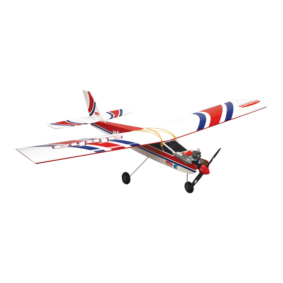
Alpha 40 ARF
Assembly Manual
Specifications
Wingspan: .............................................................. 63 in (1600mm)
Length: ................................................................ 52.5 in (1334mm)
Wing Area: ..................................................710 sq in (45.8 sq dm)
Weight: ....................................................... 5–5.5 lb (2.27–2.49 kg)
Radio: .............................................................4-channel minimum
Engine: ............................ .40–.46 2-stroke (glow), Power 25 (EP)
Advertisement
Table of Contents

Subscribe to Our Youtube Channel
Related Manuals for Hangar 9 Alpha 40 ARF


Summary of Contents for Hangar 9 Alpha 40 ARF
- Page 1 Alpha 40 ARF Assembly Manual Specifications Wingspan: .............. 63 in (1600mm) Length: ..............52.5 in (1334mm) Wing Area: ..........710 sq in (45.8 sq dm) Weight: ............5–5.5 lb (2.27–2.49 kg) Radio: .............4-channel minimum Engine: ......40–.46 2-stroke (glow), Power 25 (EP)
-
Page 2: Table Of Contents
Glossary of Terms ..............49 Safety, Precautions and Warnings ........50 Warranty Information ............50 Instructions for Disposal of WEEE by Users in the European Union .........52 2009 Official Academy of Model Aeronautics Safety Code ..52 Hangar 9 Alpha 40 ARF Assembly Manual... -
Page 3: Included Parts Listing
#4 silver flat washer Engine to motor mount 8-32 blind nut Engine mount 4-40 nylon inserted locknut Engine to motor mount Black nylon motor mount 45mm EP standoffs 2-inch (50mm) 2-blade spinner, red Hangar 9 Alpha 40 ARF Assembly Manual... -
Page 4: Using The Manual
™ • 12V 7Ah Sealed Battery (HAN102) • Power Panel (HAN106) • Blue Block After Run Oil (EVOX1001) • Cleaner and towels The Spektrum trademark is used with permission of Bachmann Industries, Inc. Hangar 9 Alpha 40 ARF Assembly Manual... -
Page 5: Servo Installation-Fuselage
Important: You will need to connect a 6-inch (152mm) extension in the Aileron port of the receiver to connect to the servo used for the Ailerons. Leave the extension plugged into the receiver when unplugging the servos. Hangar 9 Alpha 40 ARF Assembly Manual... -
Page 6: Glow Engine Installation
The nuts are not to be tightened at this time so the mount can be positioned for your engine. The bolts wil be tightened once the engine has been secured to the mounting rails. Hangar 9 Alpha 40 ARF Assembly Manual... - Page 7 Slide the screws through the holes in the engine mount flange. Step 7 Use a 3/32-inch hex wrench or ball driver and a 1/4-inch nut driver to tighten the hardware securing the engine to the engine mounting rails. Hangar 9 Alpha 40 ARF Assembly Manual...
-
Page 8: Fuel Tank Installation
Locate the items necessary to install the fuel tank in the fuselage. Step 9 Slide the piece cut in the previous step on a nylon clevis. Thread the clevis 10-turns onto the threaded end of the 2-56 x 16 -inch throttle pushrod wire. Hangar 9 Alpha 40 ARF Assembly Manual... - Page 9 The tank sides of the fuselage when installed properly. Once fit, use will fit snug against the back of the firewall when installed. medium CA to glue the braces to the fuselage sides. Hangar 9 Alpha 40 ARF Assembly Manual...
-
Page 10: Muffler Installation
Use scissors or a hobby knife and #11 blade to trim the length of the line if necessary so they don’t interfere with the operation of the engine. Hangar 9 Alpha 40 ARF Assembly Manual... -
Page 11: Propeller And Spinner - Glow Engine Installation
Make sure the propeller has not moved from its position as described back in Step 3. If it has, the spinner cone will not be able to be installed in the following steps. Hangar 9 Alpha 40 ARF Assembly Manual... -
Page 12: Electric Motor Installation
Open end wrench: 5/16-inch Phillips screwdriver: #1 tighten the screws. Drill bit: 11/64-inch (4.5mm) Hex wrench of ball driver: 9/64-inch, 2.5mm Step 1 Locate the parts necessary to install the electric motor on the fuselage. Hangar 9 Alpha 40 ARF Assembly Manual... - Page 13 Apply a drop of threadlock on each of the screws used to attach the X-mount to the motor. Use a #1 Phillips screwdriver to secure the mount to the motor. Step 4 Place a drop of threadlock on each of the screws. Hangar 9 Alpha 40 ARF Assembly Manual...
- Page 14 Follow components you may need to change the motor wires later the instructions provided with the speed control to when checking the operation of the motor. complete this step. Hangar 9 Alpha 40 ARF Assembly Manual...
- Page 15 30-minute epoxy to glue the trays to the sides of the fuselage. Make sure they are secure so the weight of the battery does not cause them to come loose. Hangar 9 Alpha 40 ARF Assembly Manual...
- Page 16 Use a 2.5mm hex wrench or ball the tray and battery to prevent it from doing so. driver to tighten the screw. Use two screws and washers to secure the hatch to the fuselage. Hangar 9 Alpha 40 ARF Assembly Manual...
-
Page 17: Propeller And Spinner Installation-Electric Motor
Step 7 Slide the spinner cone over the propeller. It will fit into the grooves in the spinner backplate when installed. Hangar 9 Alpha 40 ARF Assembly Manual... -
Page 18: Landing Gear Installation
The landing gear installation is identical if you are tighten the screws. using a glow engine or electric motor. Step 1 Locate the items necessary to install the nose gear and main landing gear on your aircraft. Hangar 9 Alpha 40 ARF Assembly Manual... - Page 19 Use a 1.5mm hex wrench or ball driver to tighten the setscrew. Hangar 9 Alpha 40 ARF Assembly Manual...
- Page 20 This is bottom of the fuselage using rubbing alcohol and a necessary to accept the radius of the bend on the main gear paper towel. assemblies, allowing them to fit snug in the slot. Hangar 9 Alpha 40 ARF Assembly Manual...
-
Page 21: Receiver Installation - Electric Motor Option
#4 x 3/8-inch wood screws. Use a #2 Phillips screwdriver to tighten the screws. Step 2 Mount the receiver to the bottom of the fuselage using hook and loop tape. Hangar 9 Alpha 40 ARF Assembly Manual... -
Page 22: Receiver Installation- Glow Engine Option
Remove the radio tray from the fuselage. Use a drill and in the fuselage. 3/32-inch (2.5mm) drill bit to drill a hole in the support block for the screw that will secure the position of the radio tray. Hangar 9 Alpha 40 ARF Assembly Manual... - Page 23 Place the receiver and receiver battery in the fuselage. Use scissors to cut small pieces of 1/4-inch (6mm) foam to isolate the receiver and battery from each other, as well as from the fuselage sides. Hangar 9 Alpha 40 ARF Assembly Manual...
-
Page 24: Wing Dowel Installation
Use a #1 Phillips screwdriver to tighten the screw. Step 2 Use a hobby knife with a #11 blade to remove the covering from the fuselage for the wing dowels. Hangar 9 Alpha 40 ARF Assembly Manual... -
Page 25: Fin And Stabilizer Installation
Step 2 Use a hobby knife with a #11 blade to remove the covering from the notch at the front of the stabilizer. Also remove the covering from the pre-drilled holes in the stabilizer. Hangar 9 Alpha 40 ARF Assembly Manual... - Page 26 Use a hobby knife with a #11 blade to remove the covering on damage the underlying wood. the bottom of the fuselage for the stabilizer attachment screw. Step 4 Slide the two #4 washers onto the threaded rods from the bottom of the stabilizer. Hangar 9 Alpha 40 ARF Assembly Manual...
- Page 27 Insert the screw into the hole in the fuselage and through the stabilizer to the preinstalled blind nut on the top of the stabilizer. Use a #2 Phillips screwdriver to tighten the screw. Hangar 9 Alpha 40 ARF Assembly Manual...
-
Page 28: Throttle Linkage Connection
Pull the throttle linkage so the carburetor at the engine is closed. Use a felt-tipped pen to mark the pushrod wire where it crosses the hole on the servo horn that is 1/2- inch (13mm) from the center of the horn. Hangar 9 Alpha 40 ARF Assembly Manual... - Page 29 You may need to use pliers to snap the screwdriver. Use diagonal cutters to remove any unused link onto the wire. arms from the horn so they don’t interfere with the operation of the servo. Hangar 9 Alpha 40 ARF Assembly Manual...
-
Page 30: Elevator Linkage Installation
Step 2 Slide the 2-56 x 28-inch pushrod wire into the tube in the fuselage for the elevator. Make sure the threaded end goes into the tube first. Hangar 9 Alpha 40 ARF Assembly Manual... - Page 31 Use a ruler to make sure the elevator is centered with the stabilizer. Use a felt-tipped pen to mark the pushrod wire where it crosses the hole on the servo horn. Hangar 9 Alpha 40 ARF Assembly Manual...
- Page 32 Use diagonal cutters to remove any unused snaps on the wire. You may need to use pliers to snap the arms from the horn so they don’t interfere with the operation link onto the wire. of the servo. Hangar 9 Alpha 40 ARF Assembly Manual...
-
Page 33: Rudder And Steering Linkage Installation
Use a pin vise and 5/64-inch (2mm) drill bit to enlarge a hole on the servo horn that is 9/16-inch (14mm) from the center of the servo horn on the side closest to the steering pushrod wire. Hangar 9 Alpha 40 ARF Assembly Manual... - Page 34 Use a hobby knife and #11 blade to trim the covering on the fuselage where the pushrod exits. Step 5 Remove the horn from the servo. Insert the pushrod connector in the outer hole of the servo horn. Hangar 9 Alpha 40 ARF Assembly Manual...
- Page 35 Use a ruler to make sure the rudder is centered with the fin. Use a felt-tipped pen to mark the pushrod wire where it crosses the hole enlarged previously on the servo horn. Attach clevis to center hole Hangar 9 Alpha 40 ARF Assembly Manual...
- Page 36 The horn will fit against the bend in the wire. Slide the steering pushrod wire through the pushrod connector. Use the screw from the servo and a #1 Phillips screwdriver to attach the horn to the rudder servo. Hangar 9 Alpha 40 ARF Assembly Manual...
-
Page 37: Aileron Servo Installation
Do not use the rudder trim to adjust the steering. Use the rudder trim for in-flight corrections only. Step 18 If you are going to step away from your model, make sure to turn off both the transmitter and receiver. Hangar 9 Alpha 40 ARF Assembly Manual... - Page 38 Place 2–3 drops of thin CA in each of the holes to harden the surrounding wood. This will make the screws more secure and less likely to vibrate loose. Hangar 9 Alpha 40 ARF Assembly Manual...
- Page 39 Connect the aileron linkages to the holes of the servo horn that were enlarged in the previous steps. Use the pushrod snap links for this step. Hangar 9 Alpha 40 ARF Assembly Manual...
-
Page 40: Wing Assembly
Slide the remaining wing panel onto the wing tube. Use the supplied clear tape to secure the joint between the two wing panels. Make sure to apply the tape to both the top and bottom of the joint. Hangar 9 Alpha 40 ARF Assembly Manual... -
Page 41: Optional: Gluing The Wing Halves
If they wing roots as shown. are not, thread the clevis in or out as necessary to align the aileron and wing. Make sure to align both aileron at this time. Hangar 9 Alpha 40 ARF Assembly Manual... - Page 42 Use a paper towel and rubbing alcohol to remove any epoxy on the bottom of the wing, and the white covering on the that seeps from the joint between the two wing panels. top of the wing. Hangar 9 Alpha 40 ARF Assembly Manual...
-
Page 43: Wing Installation
Make sure to align both aileron at this time. Locate the aileron extension that is inside the fuselage. Align the colors from the aileron servo lead with the extension so they match, then plug them together. Hangar 9 Alpha 40 ARF Assembly Manual... -
Page 44: Checking The Control Surface Movement
Check the movement of the elevator with the radio system. Pulling the elevator/aileron stick (right stick on the transmitter) back will make the airplane elevator move up. This will cause the aircraft to pitch up in flight. Hangar 9 Alpha 40 ARF Assembly Manual... -
Page 45: Checking The Throttle Operation
When the rudder/throttle stick (left side of the transmitter) is moved right, the rudder should also move right. This will cause the aircraft to turn right while on the ground and to yaw right while in flight. Hangar 9 Alpha 40 ARF Assembly Manual... -
Page 46: Balancing Your Alpha Arf
Marking the Balance Point The first step in balancing your Alpha 40 ARF is to mark the location for the balance point. The ideal balance point for the Alpha ARF is 2 –3 inches (70–76mm) back from the leading... -
Page 47: Control Throws
Hangar 9 Alpha 40 ARF Assembly Manual... -
Page 48: Maintaining Your Model
If they are reconnected incorrectly, the servo for any wear or damage. If they look worn or in bad engine will not run properly. shape, replace them as well. Hangar 9 Alpha 40 ARF Assembly Manual... -
Page 49: Safety Do's And Don'ts For Pilots
It is attached to the bottom of the fuselage. Step 7 All servo pigtails and switch harness plugs should be secured in the receiver. Make sure that the switch harness moves freely in both directions. Hangar 9 Alpha 40 ARF Assembly Manual... -
Page 50: Safety, Precautions And Warnings
The rudder improper installation, operation, maintenance, or attempted controls the yaw axis. repair by anyone other than Horizon. Return of any goods by Purchaser must be approved in writing by Horizon before shipment. Hangar 9 Alpha 40 ARF Assembly Manual... - Page 51 Repair or replacement decisions are at the sole discretion of Horizon Hobby. Please call 877-504-0233 or e-mail us at productsupport@ horizonhobby.com with any questions or concerns regarding this product or warranty. Hangar 9 Alpha 40 ARF Assembly Manual...
-
Page 52: Instructions For Disposal Of Weee By Users In The European Union
Model Rocketry Safety Code; however, they may not be launched from model aircraft. Officially designated AMAAir Show Teams (AST) are authorized to use devices and practices as defined within the Air Show Advisory Committee Document. Hangar 9 Alpha 40 ARF Assembly Manual... - Page 53 5. I will operate my model aircraft using only radio- control frequencies currently allowed by the Federal Communications Commission (FCC). Only individuals properly licensed by the FCC are authorized to operate equipment on Amateur Band frequencies. Hangar 9 Alpha 40 ARF Assembly Manual...
- Page 54 Horizon Hobby UK Horizon Hobby Deutschland GmbH Horizon Hobby USA Units 1-4 Ployters Rd Hamburger Strasse 10 4105 Fieldstone Road Staple Tye 25335 Elmshorn Champaign, Illinois 61822 Harlow, Essex Germany CM18 7NS +49 4121 46199 60 (877) 504-0233 United Kingdom +44 (0) 1279 641 097 ©...
Need help?
Do you have a question about the Alpha 40 ARF and is the answer not in the manual?
Questions and answers