Table of Contents
Advertisement
Quick Links
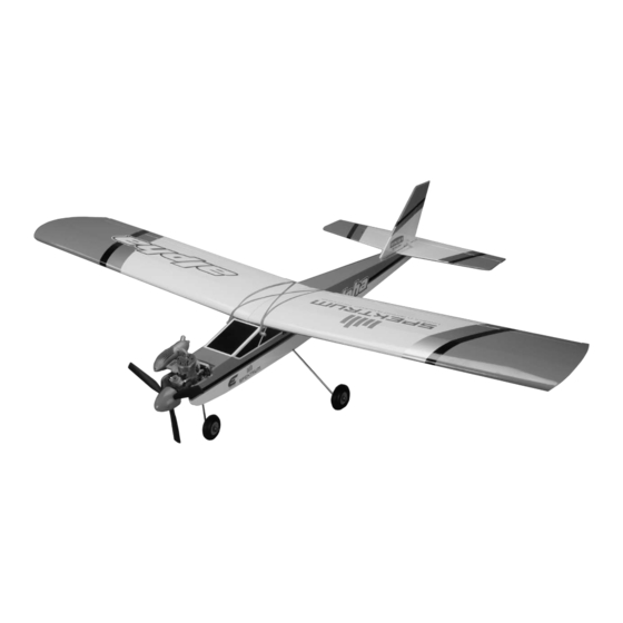
Alpha 40 with Spektrum
Specifications
Wingspan .......................................63.0 in (160 cm)
Length w/Spinner ...........................52.5 in (133 cm)
Wing Area ............................710 sq in (45.8 sq dm)
Flying Weight ........... 5.25 - 5.75 lb (2.40 - 2.60 kg)
12843.1_HAN_Alpha40_SpektrumManual.indd 1
Assembly mAnuAl
Engine Size .............................. .45 cu in (included)
Radio...............................Spektrum DX5e (included)
Servos ........................................4 servos (included)
DX5e
™
The Spektrum trademark is used with
permission of Bachmann Industries, Inc. US
patent 7,391,320. Other patents pending.
6/4/10 10:17:48 AM
Advertisement
Table of Contents

Related Manuals for Hangar 9 Alpha 40


Summary of Contents for Hangar 9 Alpha 40
- Page 1 Alpha 40 with Spektrum DX5e ™ Assembly mAnuAl Specifications Wingspan ........63.0 in (160 cm) Engine Size .......45 cu in (included) Length w/Spinner ......52.5 in (133 cm) Radio.......Spektrum DX5e (included) Wing Area ......710 sq in (45.8 sq dm) Servos ........4 servos (included) Flying Weight ...
-
Page 2: Table Of Contents
NOTICE: All instructions, warranties and other collateral documents are subject to change at the sole discretion of Horizon Hobby, Inc. For up-to-date product literature, visit http://www.horizonhobby.com and click on the support tab for this product. Meaning of Special Language: The following terms are used throughout the product literature to indicate various levels of potential harm when operating this product: NOTICE: Procedures, which if not properly followed, create a possibility of physical property damage AND little or no possibility of injury. -
Page 3: Using The Manual
Section 22: Maintaining Your Alpha 40 RTF ........ -
Page 4: Optional Parts And Accessories
• Long Reach Glow Plug Wrench (HAN2510) • Super Glow Plug (EVOGP1) • Transmitter Stand (HAN2525) • Angle Pro Throw/Incidence Meter (HAN192) • Hangar 9 Straw Hat (HANP303) • Sealing Iron ( HAN101) • Sealing Iron Sock (HAN141) • Heat Gun (HAN100) •... -
Page 5: Phoenix Rc
® and love. Brands like JR Heli, E-flite and Hangar 9 . You can even fly with other pilots around the world via an internet multiplayer mode. Once you’ve mastered flying on your computer, you can use your DX5e to fly the real planes and helis you’ve been practicing with. -
Page 6: Contents Of Kit
Contents of Kit A. HAN4401 Wing Set w/Wing Tube HAN304 2.5-inch Wheels (2) B. HAN4402 Fuselage HAN305 2.75-inch Wheels (2) C. HAN4403 Tail Set G. EVOE200S Evolution Power System D. HAN4404 Aluminum Wing Tube Orange Spinner E. HAN4405 Decal Sheet H. -
Page 7: Section 1: Landing Gear Installation
Section 1: Landing Gear Installation Required Parts Step 3 • Fuselage • Landing gear strap (2) Repeat Steps 1 and 2 to install the remaining landing • Main landing gear assembly (2) gear assembly. • 3mm x 12mm sheet metal screw (4) Required Tools and Adhesives •... - Page 8 Section 1: Landing Gear Installation Step 5 Use a #2 Phillips screwdriver and two 3mm x 12mm sheet metal screws to secure one of the straps to the bottom of the fuselage. Step 6 Repeat Steps 4 and 5 to secure the remaining landing gear strap to the bottom of the fuselage.
-
Page 9: Section 2: Fin And Stabilizer Installation
Section 2: Fin and Stabilizer Installation Required Parts Step 3 • Fin/Rudder assembly • #4 washer (4) Use scissors to cut the end of the tube of threadlock. Cut • Stabilizer/Elevator assembly • Wing nut (2) only the corner so the application of the threadlock can be controlled easier than if the whole end were cut off. - Page 10 Section 2: Fin and Stabilizer Installation o Step 5 Step 7 Thread the two wing nuts onto the threaded rods to secure Locate a #4 washer and 3mm x 10mm machine screw. the fin to the stabilizer. Don't over-tighten the wing nut and Slide the washer onto the screw, then apply a small damage the underlying wood.
- Page 11 Section 2: Fin and Stabilizer Installation Step 9 Step 11 Repeat Steps 7 and 8 to install the second screw. Connect the clevis to the center hole of the rudder control horn. The alignment of the rudder will be covered later in this manual.
-
Page 12: Section 3: Propeller And Spinner Installation
Section 3: Propeller and Spinner Installation Required Parts Step 3 • Fuselage assembly • Spinner assembly Slide the propeller onto the engine crankshaft. The • Propeller blades of the propeller will be positioned against the bosses for the spinner screws of the spinner backplate Required Tools and Adhesives as shown below. - Page 13 Section 3: Propeller and Spinner Installation Step 5 Step 7 Thread the propeller nut onto the engine crankshaft. Slide the spinner cone over the propeller. It will fit into the grooves in the spinner backplate when installed. Step 6 ...
-
Page 14: Section 4: Wing Dowel Installation
Section 4: Wing Dowel Installation Required Parts Step 3 • Fuselage assembly • Wing dowel (2) Use the following photo to confirm the location of the wing dowel installation in the fuselage. Required Tools and Adhesives • Thin CA ... -
Page 15: Section 5: Wing Assembly
Section 5: Wing Assembly Required Parts Step 3 • Wing panel (left and right) • Wing tube As you slide the wing panels together, make sure the • Clear tape aluminum pin at the back (trailing edge) of the wing slides into the hole of the receiving wing panel. -
Page 16: Section 5B: Optional: Gluing The Wing Halves
Section 5: Wing Assembly Step 5 Connect the clevises from the aileron pushrods to the aileron control horns. The alignment of the ailerons will be checked later in this manual. Section 5b: Optional: Gluing the Wing Halves Required Parts ... - Page 17 Section 5b: Gluing the Wing Halves Step 2 Step 4 Mix 1/2-ounce total (15ML) of 30-minute epoxy. Use an As you slide the wing panels together, make sure the pin epoxy brush to apply a thin layer of epoxy to each of the at the back (trailing edge) of the wing slides into the hole wing roots as shown.
- Page 18 Section 5b: Optional: Gluing the Wing Halves Step 6 Step 8 Use tape (painter's tape suggested) to keep the two wing Connect the clevises from the aileron pushrods to the panels tight against each other until the epoxy is fully aileron control horns.
-
Page 19: Section 6: Centering The Control Surfaces
Section 6: Centering the Control Surfaces Required Parts Checking the Rudder • Assembled airframe Center the rudder stick and trim. If necessary, detach the clevis from the control horn and thread the clevis in or out Required Tools and Adhesives on the rudder pushrod until the rudder is aligned with the •... -
Page 20: Section 7: Wing Installation
Section 7: Wing Installation Required Parts Step 3 • Wing assembly • Fuselage assembly Install a second set of rubber bands on the wing • Rubber band (10) as shown. Step 1 Locate the aileron extension that is inside the fuselage. Align the colors from the aileron servo lead with the extension so they match, then plug them together. -
Page 21: Section 8: Your Spektrum Dx5E Radio System
Section 8: Your Spektrum DX5e Radio System Antenna Trainer Switch HI/LO Rate Switch Channel 5 Switch Throttle and Aileron and Rudder Stick Elevator Stick Throttle Trim Elevator Trim Rudder Trim Aileron Trim On/Off Switch Trainer Port Charge Jack Mix Switch Reversing Switches Mode 2 Section 9: Battery Installation... -
Page 22: Section 10: Digital Trims
Section 10: Digital Trims The DX5e features digital trims. Each time a trimmer is moved the servo output will change one step. If the trimmer is held, the output will scroll in that direction until the trimmer is released or the output reaches its end. Throttle Trim Elevator Trim Rudder Trim... -
Page 23: Section 13: Binding
The transmitter and port in the receiver and plug it into the aileron extension. receiver for your Alpha 40 RTF has already been bound, Plug the bind plug into the battery/bind port in the but this section has been included as reference. - Page 24 Section 13: Binding Step 3 Step 5 Turn on the receiver switch. The LED on the receiver Pull and hold the trainer switch on the top of the should be flashing, indicating that the receiver is ready transmitter while turning on the power switch. Turning to bind.
- Page 25 Section 13: Binding Step 6 Step 7 After the system is bound, turn off the power on the Unplug the power lead from the aileron extension and transmitter and receiver. Then remove the bind plug from plug it back into the power/bind port of the receiver. Turn the receiver and store it in a convenient place.
-
Page 26: Section 14: Checking The Control Surface Movement
Section 14: Checking the Control Surface Movement Required Parts Check the movement of the elevator with the radio system. Pulling the elevator/aileron stick (right stick on the • Transmitter • Assembled airframe transmitter) back will make the airplane elevator move up. The control direction has been set at the This will cause the aircraft to pitch up in flight. - Page 27 Section 14: Checking the Control Surface Movement Checking the Ailerons Check the movement of the aileron using the transmitter. When the elevator/aileron stick is moved right, the right Check the movement of the aileron using the transmitter. aileron will move up and the left aileron will move down. When the aileron/elevator stick is moved left, the left This will cause the aircraft to roll right in flight.
- Page 28 Section 14: Checking the Control Surface Movement Checking the Rudder Check the movement of the rudder using the transmitter. When the rudder/throttle stick (left side of the transmitter) Check the movement of the rudder using the transmitter. is moved right, the rudder should also move right. This When the left stick is moved left, the rudder should also will cause the aircraft to turn right while on the ground move left.
- Page 29 Section 14: Checking the Control Surface Movement Reversing Direction of Flight Controls If you find any of the control surfaces moving in the opposite direction (example shown below), you will need to use the Servo Reversing feature of your radio system. Follow the instructions included with your radio to change the servo reversing of the offending control surface.
-
Page 30: Section 15: Hi/Lo Rate
Section 15: Hi/Lo Rate The DX5e offers a high/low rate function on aileron, elevator and rudder. When the HI/LO rate switch is in the upper position or “HI” position, 100% travel is achieved on the aileron, elevator and rudder channels. When the switch is in the lower position, a reduced travel of 70% is achieved on the aileron, elevator and rudder channels. -
Page 31: Section 16: Setting The Control Throws
Section 16: Setting the Control Throws Required Parts Aileron Throw • Transmitter • Assembled airframe Use a ruler to check the amount of throw for the aileron. Move the aileron stick fully and check the measurements. Required Tools and Adhesives Adjust the radio as necessary following the instructions •... -
Page 32: Section 17: Checking The Throttle Operation
Section 17: Checking the Throttle Operation Required Parts Throttle Open • Fuselage assembly • Transmitter Move the throttle stick up, or the fully open, position as shown. The carburetor should open without binding the Throttle Closed throttle servo. If the servo binds, you will need to adjust the clevis at the carburetor by threading it in or out to Move the throttle stick and trim down to the fully closed eliminate any binding. - Page 33 Section 17: Checking the Throttle Operation Throttle set to Idle Move the throttle stick down to the fully closed position. Move the trim lever upward to open the carburetor roughly 1/16-inch (1.5mm). This will be the idle position for your engine. The idle will be fine-tuned at the field so the engine will idle reliably without stalling for slow flight and landing procedures.
-
Page 34: Section 18: Balancing Your Alpha Rtf
Section 18: Balancing Your Alpha RTF In order for your Alpha 40 RTF to fly correctly, you will Balanced Correctly need to check the balance of the plane with the fuel tank empty. This is done by supporting the aircraft either using your fingers or by using a balancing stand. -
Page 35: Section 19: Flight Preparations
Adding Weights to Correct the Balance Due to manufacturing differences, it is possible that the Alpha 40 RTF may not be balanced properly. Weights can be added to either the tail or the nose of your Alpha RTF if it does not balance properly. Stick-on weights available at your local hobby store are the easiest to use, and come in sizes that are easily placed on your plane. -
Page 36: Section 20: How To Range Test The Dx5E
Section 20: How to Range Test the DX5e Before each flying session, and especially with a new model, it is important to perform a range check. The DX5e incorporates a range testing system which, when placed in the RANGE CHECK mode with the trainer switch activated and held, reduces the output power, allowing a range check. -
Page 37: Section 21: Starting And Adjusting The Evolution Engine
We recommend using high quality Cool Power Omega, Step 6 Hangar 9® AeroBlend™ or Power Master fuels containing 10 to 15% Nitro. The Evolution Engine has been test Turn the engine over using an electric starter. run using these fuels. If another brand of fuel is used, it... -
Page 38: Section 22: Maintaining Your Alpha 40 Rtf
Inspect the control horns to make sure they have not your Alpha 40 RTF. Doing so will keep your aircraft in crushed the wood of the control surface. If so, remove the the best flying condition. - Page 39 Section 22: Maintaining Your Alpha 40 RTF Check the Engine Mount Bolts Adjusting the Steering Trim Remove the spinner and propeller from the engine. When adjusting the steering trim, do not use the trim on Remove the exhaust stacks from the fuselage, and the transmitter.
-
Page 40: Safety Do's And Don'ts For Pilots
Safety Do’s and Don’ts for Pilots • Ensure that your batteries have been properly • Do not fly during adverse weather conditions. charged prior to your initial flight. Poor visibility can cause disorientation and loss of control of your aircraft. Strong winds can cause •... -
Page 41: Glossary Of Terms
Glossary of Terms Ailerons: Each side of this airplane has a hinged control Nose Gear: The part of the landing gear that is attached surface (aileron), located on the trailing edge of the to the nose of the fuselage. The nose gear is usually wing. -
Page 42: Building And Flying Notes
Building and Flying Notes 12843.1_HAN_Alpha40_SpektrumManual.indd 42 6/4/10 10:18:51 AM... -
Page 43: 2008 Official Ama National Model Aircraft Safety Code
2010 Official Academy of Model Aeronautics Safety Code GENERAL 8. I will not operate model aircraft carrying pyrotechnic devices which explode, burn, or propel a projectile 1. A model aircraft shall be defined as a non-human of any kind. Exceptions include Free Flight fuses or carrying device capable of sustained flight in the devices that burn producing smoke and are securely atmosphere. - Page 44 2010 Official Academy of Model Aeronautics Safety Code Radio Control Control Line 1. I will subject my complete control system (including 1. All model flying shall be conducted in a manner to the safety thong where applicable) to an inspection avoid over flight of unprotected people.
-
Page 45: Warranty Information
Warranty Information Warranty Period If you as the Purchaser or user are not prepared to accept the liability associated with the use of this Product, you are advised to return this Exclusive Warranty- Horizon Hobby, Inc., (Horizon) warranties that Product immediately in new and unused condition to the place of the Products purchased (the "Product") will be free from defects in purchase. -
Page 46: Fcc Information
Non-Warranty Repairs request with your repair. Non-warranty repair estimates will be billed a minimum of ½ hour of labor. In addition you will be billed for return Should your repair not be covered by warranty the repair freight. Horizon accepts money orders and cashiers checks, will be completed and payment will be required without notification or estimate of the expense unless the expense as well as Visa, MasterCard, American Express, and Discover cards. -
Page 47: Compliance Information For The European Union
Declaration of Conformity (in accordance with ISO/IEC 17050-1) No. HH20100526U1 Product(s): HAN Alpha 40 RTF Item Number(s): HAN4400 Equipment class: The object of declaration described above is in conformity with the requirements of the specifications listed below, following the provisions of the European R&TTE directive 1999/5/EC:... - Page 48 © 2010 Horizon Hobby, Inc. 12843.1 Revised 5/10 12843.1_HAN_Alpha40_SpektrumManual.indd 48 6/4/10 10:18:54 AM...
Need help?
Do you have a question about the Alpha 40 and is the answer not in the manual?
Questions and answers