Table of Contents
Advertisement
Quick Links
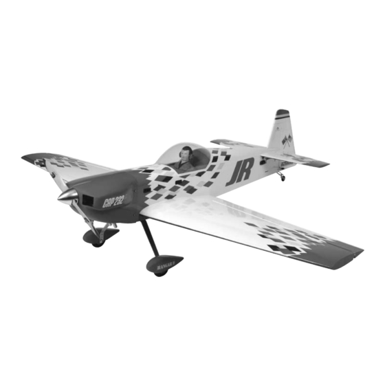
CAP 232G ARF
Specifications
Wingspan:. . ...................................80.5.in.(2045mm)
Wing.Area:..........................1260.sq.in.(81.2.sq.dm)
Assembly mAnuAl
Length:. . ........................................74.5.in.(1892mm)
Weight:. . ...............................15–16.lb.(6.8kg–7.3kg)
®
Advertisement
Table of Contents

Related Manuals for Hangar 9 CAP 232G ARF


Summary of Contents for Hangar 9 CAP 232G ARF
- Page 1 ® CAP 232G ARF Assembly mAnuAl Specifications Wingspan:........80.5.in.(2045mm) Length:..........74.5.in.(1892mm) Wing.Area:......1260.sq.in.(81.2.sq.dm) Weight:.........15–16.lb.(6.8kg–7.3kg)
-
Page 2: Table Of Contents
Table of Contents Contents.of.Kit..............3 UltraCote Covering.Colors.. -
Page 3: Contents.of.kit
Contents of Kit Replacement Parts A.. HAN2901. Fuselage.w/Hatch B.. HAN2902. Fuselage.Hatch C.. HAN2903. Left.Wing.w/Aileron D.. HAN2904. Right.Wing.w/Aileron E.. HAN2905. Wing.Tube F.. HAN2906. Stabilizer.w/Elevator G.. HAN2907. Stabilizer.Tube.Set H.. HAN2908. Fin.w/Rudder I.. HAN2909. Canopy J.. HAN2910. Landing.Gear.w/Axles K.. HAN2911. Wheel.Pant.Set L.. HAN2912. Painted.Cowl M.. -
Page 4: Required.tools.and.adhesives
Required Tools and Adhesives Tools •.Drill. •.T-pins •.Adjustable.wrench. •.Hex.wrench:.3/32",.5/32" •.Hobby.knife. •.Hobby.scissors •.Phillips.screwdriver. •.Pliers •.Side.cutters. •.Nut.driver:.5.5mm •.Crimping.tool •.. D rill.bits:.1/16".(1.5mm),.5/64".(2mm),. 5/32".(4mm),.7/32".(4.5mm) Adhesives •.6-minute.epoxy.(HAN8000). •.30-minute.epoxy.(HAN8002) •.Thin.CA. . •.Canopy.glue •.Zap-A-Dap-A-Goo. •.Threadlock •.Medium.CA. •.Pacer.hinge.glue.(PT-55) Other Required Items •.Epoxy.brushes. •.Felt-tipped.pen.or.pencil •.Measuring.device.(e.g..ruler,.tape.measure). •.Mixing.sticks.for.epoxy •.Paper.towels. •.Rubbing.alcohol •.Masking.tape. •.Sanding.bar •.Sandpaper. -
Page 5: Limited.warranty.&.Limits.of.liability
Limited Warranty & Limits of Liability Pursuant.to.this.Limited.Warranty,.Horizon.Hobby,.Inc..will,.at.its.option,.(i).repair.or.(ii).replace,.any.product.determined. by.Horizon.Hobby,.Inc..to.be.defective..In.the.event.of.a.defect,.these.are.your.exclusive.remedies. This.warranty.does.not.cover.cosmetic.damage.or.damage.due.to.acts.of.God,.accident,.misuse,.abuse,.negligence,. commercial.use,.or.modification.of.or.to.any.part.of.the.product..This.warranty.does.not.cover.damage.due.to.improper. installation,.operation,.maintenance,.or.attempted.repair.by.anyone.other.than.an.authorized.Horizon.Hobby,.Inc..service. center..This.warranty.is.limited.to.the.original.purchaser.and.is.not.transferable..In.no.case.shall.Horizon.Hobby’s. liability.exceed.the.original.cost.of.the.purchased.product.and.will.not.cover.consequential,.incidental.or.collateral. damage..Horizon.Hobby,.Inc..reserves.the.right.to.inspect.any.and.all.equipment.involved.in.a.warranty.claim..Repair. or.replacement.decisions.are.at.the.sole.discretion.of.Horizon.Hobby,.Inc..Further,.Horizon.Hobby.reserves.the.right.to. change.or.modify.this.warranty.without.notice. REPAIR.OR.REPLACEMENT.AS.PROVIDED.UNDER.THIS.WARRANTY.IS.THE.EXCLUSIVE.REMEDY.OF.THE.CONSUMER.. HORIZON.HOBBY,.INC..SHALL.NOT.BE.LIABLE.FOR.ANY.INCIDENTAL.OR.CONSEQUENTIAL.DAMAGES. As.Horizon.Hobby,.Inc..has.no.control.over.use,.setup,.final.assembly,.modification.or.misuse,.no.liability.shall.be. assumed.nor.accepted.for.any.resulting.damage.or.injury..By.the.act.of.use,.setup.or.assembly,.the.user.accepts.all. resulting.liability. If.you.as.the.purchaser.or.user.are.not.prepared.to.accept.the.liability.associated.with.the.use.of.this.product,.you.are. advised.to.return.this.product.immediately.in.new.and.unused.condition.to.the.place.of.purchase. Safety Precautions This.is.a.sophisticated.hobby.product.and.not.a.toy..It.must.be.operated.with.caution.and.common.sense.and.requires. some.basic.mechanical.ability..Failure.to.operate.this.product.in.a.safe.and.responsible.manner.could.result.in.injury.or. damage.to.the.product.or.other.property..This.product.is.not.intended.for.use.by.children.without.direct.adult.supervision. The.product.manual.contains.instructions.for.safety,.operation.and.maintenance..It.is.essential.to.read.and.follow.all.the. instructions.and.warnings.in.the.manual,.prior.to.assembly,.setup.or.use,.in.order.to.operate.correctly.and.avoid.damage. or.injury. Questions, Assistance, and Repairs Your.local.hobby.store.and/or.place.of.purchase.cannot.provide.warranty.support.or.repair..Once.assembly,.setup.or.use. of.the.product.has.been.started,.you.must.contact.Horizon.Hobby,.Inc..directly..This.will.enable.Horizon.to.better.answer. your.questions.and.service.you.in.the.event.that.you.may.need.any.assistance. Questions or Assistance For.questions.or.assistance,.please.direct.your.email.to.productsupport@horizonhobby.com,.or.call.877.504.0233.toll. -
Page 6: Inspection.or.repairs
Inspection or Repairs If.your.product.needs.to.be.inspected.or.repaired,.please.call.for.a.Return.Merchandise.Authorization.(RMA)..Pack.the. product.securely.using.a.shipping.carton..Please.note.that.original.boxes.may.be.included,.but.are.not.designed.to. withstand.the.rigors.of.shipping.without.additional.protection..Ship.via.a.carrier.that.provides.tracking.and.insurance.for. lost.or.damaged.parcels,.as.Horizon.Hobby,.Inc..is.not.responsible.for.merchandise.until.it.arrives.and.is.accepted.at. our.facility..Include.your.complete.name,.address,.phone.number.where.you.can.be.reached.during.business.days,.RMA. number,.and.a.brief.summary.of.the.problem..Be.sure.your.name,.address,.and.RMA.number.are.clearly.written.on.the. shipping.carton. Warranty Inspection and Repairs To.receive.warranty.service,.you.must.include.your.original.sales.receipt.verifying.the.proof-of-purchase.date..Providing. warranty.conditions.have.been.met,.your.product.will.be.repaired.or.replaced.free.of.charge..Repair.or.replacement. decisions.are.at.the.sole.discretion.of.Horizon.Hobby. Non-Warranty Repairs Should.your.repair.not.be.covered.by.warranty.and.the.expense.exceeds.50%.of.the.retail.purchase.cost,.you.will.be. provided.with.an.estimate.advising.you.of.your.options..You.will.be.billed.for.any.return.freight.for.non-warranty.repairs.. Please.advise.us.of.your.preferred.method.of.payment..Horizon.Hobby.accepts.money.orders.and.cashiers.checks,.as. well.as.Visa,.MasterCard,.American.Express,.and.Discover.cards..If.you.choose.to.pay.by.credit.card,.please.include.your. credit.card.number.and.expiration.date..Any.repair.left.unpaid.or.unclaimed.after.90.days.will.be.considered.abandoned. and.will.be.disposed.of.accordingly. Electronics.and.engines.requiring.inspection.or.repair.should.be.shipped.to.the.following.address.(freight.prepaid): Horizon.Service.Center 4105.Fieldstone.Road Champaign,.Illinois.61822 All.other.products.requiring.inspection.or.repair.should.be.shipped.to.the.following.address.(freight.prepaid): Horizon.Product.Support 4105.Fieldstone.Road Champaign,.Illinois.61822... -
Page 7: Safety,.Precautions,.And.warnings
Safety, Precautions, and Warnings This.model.is.controlled.by.a.radio.signal.that.is.subject.to.interference.from.many.sources.outside.your.control..This. interference.can.cause.momentary.loss.of.control.so.it.is.advisable.to.always.keep.a.safe.distance.in.all.directions.around. your.model,.as.this.margin.will.help.to.avoid.collisions.or.injury. •.Always.operate.your.model.in.an.open.area.away.from.cars,.traffic,.or.people. •.Never.operate.the.model.out.into.the.street.or.populated.areas.for.any.reason.as.injury.or.damage.can.occur.. •.Never.operate.your.model.with.low.transmitter.batteries. •.. C arefully.follow.the.directions.and.warnings.for.this.and.any.optional.support.equipment.(chargers,.rechargeable. battery.packs,.etc.).that.you.use. •.Keep.all.chemicals,.small.parts.and.anything.electrical.out.of.the.reach.of.children. •.. M oisture.causes.damage.to.electronics..Avoid.water.exposure.to.all.equipment.not.specifically.designed.and.protected. for.this.purpose. Before Starting Assembly Before.beginning.the.assembly.of.the.CAP.232G,.remove.each.part.from.its.bag.for.inspection..Closely.inspect.the. fuselage,.wing.panels,.rudder,.and.stabilizer.for.damage..If.you.find.any.damaged.or.missing.parts,.contact.the.place.of. purchase. If.you.find.any.wrinkles.in.the.covering,.use.a.heat.gun.or.sealing.iron.to.remove.them..Use.caution.while.working.around. areas.where.the.colors.overlap.to.prevent.separating.the.colors. Using the Manual HAN101 – Sealing Iron HAN100 – Heat Gun HAN141 – Sealing Iron HAN150 –... -
Page 8: Section.1.-.Hinging.the.control.surfaces
Section 1 – Hinging the Control Surfaces Required Parts .Step 2 •.Elevator.(left.and.right). •.Fin Mix.one.ounce.of.30-minute.epoxy..Using.a.glue.syringe. •.Rudder. •.Hinges.(21) or.toothpick,.place.a.sufficient.amount.of.30-minute. epoxy.into.one.of.the.hinge.pockets.in.the.aileron.leading. •.Wing.panel.(right.and.left) edge.only..Install.one.of.the.hinge.points.until.the.hinge. •.Aileron.(left.and.right) pin.center.is.flush.with.the.leading.edge.of.the.aileron.. •.Stabilizer.(left.and.right) Some.epoxy.should.ooze.out.of.the.pocket.as.the.hinge.is. Required Tools and Adhesives installed..If.not,.remove.the.hinge.and.apply.more.epoxy.. After.gluing.a.few.hinges,.you’ll.get.the.hang.of.just.how. •.Syringe. •.Sandpaper.(coarse) much.epoxy.is.needed..Wipe.away.any.excess.epoxy.with. •.Toothpicks. •.Razor.saw rubbing.alcohol..Re-check.that.the.center.of.the.hinge. •.Petroleum.jelly. •.Straight.edge/ruler pin.is.flush.and.parallel.with.the.leading.edge..Continue. - Page 9 Section 1 – Hinging the Control Surfaces .Step 3 .Step 5 Allow.the.glue.to.fully.cure.for.at.least.6.hours..When. Carefully.attach.the.aileron.to.the.wing,.making.sure.the. cured,.work.each.hinge.throughout.its.full.motion.several. hinges.are.inserted.in.their.respective.hinge.pockets.. times.using.your.hands..This.will.break.free.any.epoxy. Press.the.aileron.and.wing.together.such.that.less.than.a. that.may.have.found.its.way.into.the.hinge.joint..Move.the. 1/64".(.5mm).hinge.line.gap.exists.between.the.aileron. hinge.throughout.its.full.travel.until.no.resistance.is.felt.. and.wing..The.bevels.should.virtually.touch..Use.a.paper. This.may.take.as.many.as.40.or.50.times. towel.and.rubbing.alcohol.to.wipe.away.any.visible.epoxy. around.the.hinges. .Step 6 Double-check.the.hinge.gap.and.allow.the.glue.to.fully. cure.for.at.least.6.hours. .Step 4 .Step 7 Mix.one.ounce.of.30-minute.epoxy.or.use.Pacer.PT-55.
- Page 10 Section 1 – Hinging the Control Surfaces It.is.a.good.idea.to.be.sure.that.the.aileron.and.elevator. .Step 8 hinge.lines.be.sealed.airtight..Sealing.the.hinge.line.has. Glue.the.elevator.hinges.in.place.using.the.same. several.advantages..A.sealed.hinge.line.gives.a.greater. techniques.used.to.hinge.the.ailerons. control.response.for.a.given.control.deflection..It.also. offers.more.precise,.consistent.control.response.and. makes.trimming.easier..Sealing.the.aileron.and.elevator. hinge.line.is.highly.recommended..Failure.to.do.so.may. cause.control.surface.flutter,.resulting.in.a.crash. .Step 11 Cut.a.piece.of.Clear.UltraCote®.for.sealing.the.ailerons. to.approximately.1".x.32".(25mm.x.810mm)..Fold.the. UltraCote.down.the.center.with.the.adhesive.side.to.the. outside.making.a.sharp.crease.at.the.fold. .Step 12 Remove.the.backing.from.the.UltraCote..Place.the.folded. crease.side.into.the.center.of.the.hinge.line.on.the.bottom. .Step 9 of.the.wing..Using.a.straight.edge.as.shown,.hold.one.
-
Page 11: Section.2.-.Aileron.servo.installation
Section 1 – Hinging the Control Surfaces .Step 13 .Step 15 Fully.deflect.the.aileron.in.the.up.position..Place.the. Repeat.Steps.11.through.13.for.both.elevator.halves.using. straight.edge.over.the.hinge.line.covering.that.you.just. a.1".x.15".(13mm.x.380mm).piece.of.clear.covering. ironed.down.in.Step.2.with.the.edge.of.the.straight.edge. placed.firmly.at.the.bottom.of.the.hinge.line.as.shown.. Iron.down.this.side.of.the.covering,.making.sure.the. aileron.is.fully.deflected. .Step 14 Repeat.Steps.11.through.13.for.the.remaining.aileron. hinge.gap. Section 2 – Aileron Servo Installation Required Parts .Step 1 •.8-32.flange.nut.(2). - Page 12 Section 2 – Aileron Servo Installation .Step 2 .Step 3 Tie.the.string.to.the.servo.extension.and.insert.the.servo. Mix.a.small.amount.of.30-minute.epoxy.and.lightly.coat. into.the.wing..Use.the.string.to.pull.the.servo.lead.through. the.inside.of.the.hole.in.the.aileron.and.the.8-32.x.2 ". the.wing..Position.the.servo.so.the.output.shaft.is.toward. control.horn.screw..Thread.the.screw.into.the.hole.from. the.trailing.edge.of.the.wing..Use.a.1/16".(1.5mm).drill. the.top.of.the.surface..Wipe.away.any.excess.epoxy.on.the. bit.to.drill.the.locations.for.the.servo.screws..Mount.the. wing.and.screw.with.rubbing.alcohol.and.a.paper.towel.. servos.using.the.hardware.provided.with.the.servos. Screw.the.8-32.flanged.nut.in.place.as.shown..Allow.the. epoxy.to.fully.cure. .Step 4 Screw.the.molded.swivel.link.onto.the.8-32.screw.until. the.distance.from.the.aileron.surface.to.the.top.of.the.link. is.1 ".(28.6mm).
- Page 13 Section 2 – Aileron Servo Installation .Step 5 .Step 8 Using.the.4-40.screws.(don’t.substitute.a.standard.screw). Attach.the.linkage.to.the.servo.horn.on.the.aileron... and.nuts.included,.attach.the.ball.link.to.the.outer.hole. Adjust.the.link.so.the.aileron.is.centered.at.the.same.. in.the.servo.arm.from.the.bottom.side.as.shown..The. time.as.the.servo. sequence.is.screw,.ball.link,.servo.arm.and.nut..Don’t. forget.to.use.threadlock. .Step 9 Repeat.Steps.1.through.8.for.the.remaining.wing.panel. Note:.Hangar.9®.aluminum.servo.arms. are.suggested.for.ease.of.installation.and. durability..Use.3D.1/2.Servo.Arm.4-40:. JR.(HAN3578).for.the.aileron.servos. .Step 6 Screw.a.4-40.ball.link.5.to.6.turns.onto.each.end.of.a.. ".long.aileron.linkage. .Step 7 Center.the.servo.using.the.radio.system..Attach.the.servo.
-
Page 14: Section.3.-.Wing.and.tail.installation
Section 3 – Wing and Tail Installation Required Parts .Step 3 •.Wing.panels. •.Fuselage Carefully.slide.the.remaining.wing.panel.onto.the.wing. •.Wing.tube. •.Stabilizer.tube tube.that.projects.from.the.fuselage..The.fit.may.be.tight;. use.caution.when.inserting.the.wing.panels.onto.the.wing. •.1/4-20.x.2".nylon.bolt.(2). •.3mm.washer.(4) tube.and.fuselage. •.3mm.x.15mm.machine.screw.(4) Required Tools and Adhesives •.30-minute.epoxy. •.Phillips.screwdriver •.Hobby.knife. •.Threadlock .Step 1 Remove.the.two.4-40.x1/2".screws.securing.the.hatch.. to.the.fuselage..Remove.the.hatch.and.store.it.in.a.safe. place.until.later. .Step 2 Locate.the.wing.tube.and.carefully.slide.it.into.one. - Page 15 Section 3 – Wing and Tail Installation .Step 5 .Step 8 Slide.the.aluminum.rod.and.tube.into.the.holes.in.the. Test.fit.the.rudder.assembly.to.the.fuselage..Remove.. fuselage.for.the.stabilizer..Slide.one.stabilizer.onto.the.. any.covering.from.the.fin.post.that.comes.in.contact.. rod.and.tube. with.the.fuselage..Use.30-minute.epoxy.to.glue.the.fin.. to.the.fuselage. .Step 6 Secure.the.stabilizer.using.two.3mm.washers.and.two. 3mm.x.15mm.machine.screws..Use.threadlock.on.the. screws.to.prevent.them.from.loosening.during.flight. .Step 7 Repeat.Step.6.to.secure.the.remaining.stabilizer.to.. the.fuselage.
-
Page 16: Section.4.-.Landing.gear.installation
Section 4 – Landing Gear Installation Required Parts .Step 3 •.Fuselage. •#8.lock.washer.(4) Install.the.following.items.onto.the.axle:.wheel.pant,.3/16". •.Wheel.pant.(left.and.right). •#8.washer.(4) wheel.collar,.wheel.then.another.3/16".wheel.collar. •.8-32.nylon.lock.nut.(4). •.3 ".wheel.(2) •.3/16".wheel.collar.(4). •#4.washer.(2) •.8-32.x.3/4".socket.head.bolt.(4) •.4-40.x.1/2".socket.head.screw.(4) Required Tools and Adhesives •.Hex.wrench:.5/32". •.Ruler •.Felt-tipped.pen. •.Square •.Adjustable.wrench.(small) .Step 1 Install.the.axles.in.the.landing.gear..Secure.the.axles.using. an.adjustable.wrench.and.the.nuts.provided.with.the.axles. ... -
Page 17: Section.5.-.Elevator.servo.installation
Section 4 – Landing Gear Installation .Step 5 .Step 6 Center.the.wheel.in.the.wheel.pant.and.tighten.the.collars. Repeat.Steps.3.through.5.for.the.remaining.wheel.pant. to.prevent.the.wheel.from.moving.side.to.side..Use. threadlock.on.both.setscrews. Section 5 – Elevator Servo Installation Required Parts Note:.Using.two.standard.rotation.servos.and. a.standard.“Y”.harness.for.the.elevators.will. •.8-32.flange.nut.(2). •.4-40.lock.nut.(2) result.in.them.moving.in.opposite.directions. •.Fuselage.w/stabilizer instead.of.the.same.direction..As.such,.the. •.2 ".elevator.linkage.(2) elevator.installation.will.either.require.the. •.8-32.x.2 ".control.horn.screw.(2) use.of.one.reversed.rotation.servo.and.one. •.Molded.swivel.link.(2) standard.rotation.servo.or.a.reversing.“Y”. - Page 18 Section 5 – Elevator Servo Installation .Step 1 .Step 3 Install.an.24".(610mm).servo.extension.onto.an.elevator. Mix.a.small.amount.of.30-minute.epoxy.and.lightly.coat. servo..Tie.the.servo.leads.together,.using.a.commercially. the.inside.of.the.hole.in.the.elevator.and.the.8-32.x.2 ". available.connector,.or.use.unwaxed.dental.floss.to.secure. control.horn.screw..Thread.the.screw.into.the.hole.from. the.extensions.to.prevent.them.from.coming.loose.during. the.top.of.the.elevator..Wipe.away.any.excess.epoxy.on.the. flight..If.using.a.Y-harness,.install.one.side.only.of.the.. wing.and.screw.with.rubbing.alcohol.and.a.paper.towel.. Y-harness.to.one.of.the.servos,.also.tying.knots.to.prevent. Screw.the.8-32.flange.nut.in.place.as.shown..Allow.the. disconnection..The.other.servo.will.be.hooked.up.to.the.. epoxy.to.fully.cure. Y-harness.when.installed.in.the.airplane..One.elevator. servo.will.need.to.be.a.reversed-direction.servo. .Step 2 Install.the.servo.in.the.fuselage.tail.section.with.the.output. shaft.to.the.rear.of.the.fuselage..Drill.1/16".pilot.holes. before.installing.the.screws..Using.the.screws.included. with.the.servos,.fasten.the.servos.in.place. ...
- Page 19 Section 5 – Elevator Servo Installation .Step 5 .Step 7 Remove.the.stock.servo.arms.from.the.elevator.servos.. Use.the.included.4-40.screws.and.nuts.to.attach.the.ball. and.replace.them.with.3D.XL.1/2.servo.arms..The.. link.to.the.outer.hole.in.the.arm..From.the.topside,.the. arms.need.to.face.down.as.shown..Be.sure.to.use.a.. correct.sequence.is.4-40.screw,.ball.link,.servo.arm.and. drop.of.threadlock.on.the.servo.arm.screw.if.using.. 4-40.locknut..Be.sure.to.use.threadlock. metal-geared.servos. .Step 6 Screw.a.4-40.ball.link.5.to.6.turns.onto.a.2 ".elevator. linkage..Screw.the.opposite.end.of.the.linkage.into.the. swivel.control.horn.on.the.elevator..Adjust.the.linkage. length.until.the.hole.in.the.ball.link.lines.up.with.the.outer. hole.in.the.servo.arm.when.the.elevator.is.neutral.and.the. servo.arm.is.centered. .Step 8 Repeat.Steps.1.through.7.for.the.remaining.elevator.. servo.and.linkage.
-
Page 20: Section.6A.-.Rudder.servo.installation:.pull-Pull
Section 6A – Rudder Servo Installation: Pull-Pull Required Parts .Step 2 •.Fuselage.assembly Cut.the.cable.into.two.equal.pieces..Prepare.one.end.. •.4-40.linkage. •.8-32.flange.nut.(2) of.the.pull-pull.cable.using.the.cable,.threaded.cable.. end.and.crimp..The.cable.passes.through.the.crimp,. •.4-40.locknut.(2) through.the.threaded.end,.then.back.through.the.crimp.. •.8-32.x.4".control.horn.screw Pull.the.excess.cable.tight.and.use.a.crimping.tool.to. •.4-40.x.1/2".socket.head.screw.(2) complete.the.job. Required Tools and Adhesives •.Threadlock. •.Ruler The.CAP.232G.has.two.options.for.mounting.the.rudder. servo..For.lighter.engines,.a.pull-pull.system.is.used..For. heavier.engines.a.tail-mounted.servo.is.used. The.rudder.requires.a.minimum.of.100.ounce.inch.of. servo.torque..In.the.prototype.CAP.232G.we.used.a. JRPS8411.servo.with.excellent.results..Using.servos.with. less.torque.could.result.in.blow.back. .Step 1 Thread.the.8-32.x.4".control.horn.screw.into.the.hole.in. - Page 21 Section 6A – Rudder Servo Installation: Pull-Pull .Step 4 .Step 6 Repeat.Step.3.for.the.second.cable..Tape.the.cables.to.. Adjust.the.position.of.the.threaded.end.on.the.cable.so. the.rudder.servo.tray.to.keep.them.from.moving.around. it.will.thread.into.the.ball.end.and.have.slight.tension.on. inside.the.fuselage. the.cable.to.the.rudder..It.will.take.some.time.to.get.the. position.right..Once.the.position.of.the.end.is.correct,. .Step 5 pass.the.cable.back.through.the.crimp.and.secure.the. Prepare.the.rudder.servo.arm.by.attaching.two.4-40.ball. cable..Thread.the.end.into.the.ball.end..Repeat.this.for. links.using.the.standoffs.and.4-40.lock.nuts. both.cables. Using.the.screws.included.with.the.servos,.fasten.. the.servos.in.place..You.may.find.it.helpful.to.drill.. 1/16".(1.5mm).pilot.holes.before.installing.the.screws.. Center.the.rudder.servo.and.place.the.servo.arm.onto.. the.servo. Note:.The.cables.will.cross.inside.the. fuselage.to.get.the.correct.geometry. .Step 7 With.the.radio.on,.check.the.operation.of.the.rudder.. Adjust.the.cables.so.when.the.rudder.servo.is.centered,. the.rudder.is.centered.as.well..There.will.be.tension.on.
-
Page 22: Section.6B.-.Rudder.servo.installation:.direct.linkage
Section 6B – Rudder Servo Installation: Direct Linkage Required Parts .Step 2 •.Fuselage.w/.stabilizer. •.8".rudder.linkage Remove.the.covering.from.the.rudder.servo.opening.on. •.8-32.flange.nut. •.Molded.swivel.link the.left.side.of.the.fuselage.using.a.hobby.knife..Install. the.servo.in.the.fuselage.tail.section.with.the.output.shaft. •.4-40.locknut. •.Ball.link.for.servo.arm to.the.rear.of.the.fuselage..Drill.1/16".pilot.holes.before. •.Ball.link.for.swivel.link installing.the.screws..Using.the.screws.included.with.the. •.4-40.x.1/2".socket.head.screw servos,.fasten.the.servo.in.place. •.8-32.x.2 ".control.horn.screw Required Tools and Adhesives •.Drill. •.Dental.floss.or.string •.Drill.bit:.1/16".(1.5mm) •.Aluminum.servo.arms •.Control.horn.ball.ends •.24".(610mm).Servo.Extension.(JRPA102) The.rudder.requires.a.minimum.of.100.ounce.inch. of.servo.torque..In.the.prototype.CAP.232Gwe.used. - Page 23 Section 6B – Rudder Servo Installation: Direct Linkage .Step 4 .Step 6 Screw.the.molded.swivel.link.onto.the.8-32.screw.until. Use.the.included.4-40.screws.and.nuts.to.attach.the.ball. the.distance.from.the.rudder.surface.to.the.top.of.the.link. link.to.the.outer.hole.in.the.arm..From.the.topside,.the. is.1 ".(28mm). correct.sequence.is.4-40.screw,.ball.link,.servo.arm.and. 4-40.locknut..Be.sure.to.use.threadlock. .Step 5 .Step 7 Remove.the.stock.servo.arms.from.the.rudder.servo.. and.replace.them.with.3D.XL.1/2.servo.arms..The.. Screw.a.4-40.ball.link.5.to.6.turns.onto.the.8".rudder. arms.need.to.face.down.as.shown..Be.sure.to.use.a.. linkage..Screw.the.opposite.end.of.the.linkage.into.the. drop.of.threadlock.on.the.servo.arm.screw.if.using.. swivel.control.horn.on.the.rudder..Adjust.the.linkage. metal-geared.servos. length.until.the.hole.in.the.ball.link.lines.up.with.the.outer. hole.in.the.servo.arm.when.the.rudder.is.neutral.and.the. servo.arm.is.centered.
-
Page 24: Section.7.-.Tail.wheel.installation
Section 7 – Tail Wheel Installation Required Parts .Step 3 •.Fuselage. •.Tail.wheel.assembly Remove.the.bracket.and.drill.5/64".(2mm).pilot.holes.at. •.Tail.wheel.spring.(2). •.Tiller.arm the.previously.marked.positions..Use.two.#4.x.5/8".sheet. metal.screws.to.secure.the.tail.wheel.bracket.in.place..A. •#4.x.5/8".socket.head.wood.screw.(3) hardwood.plate.is.positioned.in.the.rear.of.the.fuselage,. Required Tools and Adhesives allowing.these.screws.to.be.firmly.tightened. •.Drill. •.Felt-tipped.pen •.Drill.bit:.5/64".(2mm) .Step 1 Secure.the.tiller.arm.to.the.bottom.of.the.rudder.using. three.wood.screws..Remove.the.screws.and.apply.. 2-3.drops.of.thin.CA.into.the.holes.to.harden.the.balsa,. and.then.reinstall.the.screws. Hint:.Remove.the.screws.and.wick.thin. CA.into.the.holes.to.strengthen.the. threads..When.dry,.reinstall.the.screws. .Step 4 Use.the.tail.wheel.springs.to.make.the.connection.between. -
Page 25: Section.8.-.Engine.installation
Section 8 – Engine Installation Required Parts .Step 2 •.Fuselage. •.1/4-20.x.1".bolts.(4) Attach.the.engine.to.the.firewall.using.the.hardware. •.17".throttle.pushrod.tube. •.1/4".fuel.tubing provided.with.your.engine.from.the.inside.of.the.firewall.. Mount.the.muffler.to.the.engine. •.Nylon.clevis. •.1/4".split.washers.(4) •.13 ".throttle.pushrod. •.Cowling •#4.washer.(4). •.1/4".fuel.tube.(4) •.Clunk.(fuel.pickup). •.Metal.caps.(2) •.Fuel.tubing. •.Fuel.tank •.Rubber.stopper. •.M3.x.20.screw •.15".(380mm).tie.wrap •.4-40.x.1".socket.head.screw.(4) •.Metal.tubes.(short.and.long) Required Tools and Adhesives •.Medium.CA. •.Drill •.Ruler. •.Square •.Hobby.knife. - Page 26 Section 8 – Engine Installation .Step 5 .Step 8 Move.the.servo.to.the.throttle.open.position.using.the. Prepare.the.tubing.by.placing.a.drop.of.solder.on.the.ends. radio.system..Manually.move.the.throttle.arm.on.the. of.the.brass.tubing.as.shown..This.will.keep.the.fuel.line. carburetor.to.the.open.position..Mark.the.pushrod.where.it. from.slipping.off.the.tube.when.combined.with.Step.7. crosses.the.servo.arm..Make.a.90-degree.bend.in.the.wire. and.install.it.into.the.servo.arm. .Step 6 Check.the.movement.of.the.throttle.to.verify.there.is.. no.binding.at.either.low.or.high.throttle..If.there.is,.. make.the.necessary.adjustment.to.eliminate.any.binding.. Secure.the.pushrod.using.a.pushrod.keeper.when.all. adjustments.are.complete. .Step 7 Install.the.ignition.onto.the.engine.box..Make.any. connections.from.the.ignition.to.the.engine.using.the. instructions.provided.with.your.engine..Mounting.the. ignition.to.the.engine.box.keeps.it.away.from.the.radio.. .Step 9 Being.too.near.could.cause.radio.interference. Slide.the.tubes.onto.the.brass.tubes..Use.fine.wire.to. secure.the.tubes..The.wire.is.placed.behind.the.solder. applied.in.the.previous.step.to.keep.the.tubes.in.place.
- Page 27 Section 8 – Engine Installation .Step 12 .Step 13 Carefully.insert.the.stopper.assembly.into.the.fuel.tank.. Cut.a.piece.of.1/4".foam.the.size.of.the.bottom.of.the.fuel. Note.the.position.of.the.vent.tube;.it.must.be.up.at.the. tank..Secure.the.fuel.tank.to.the.fusel.tank.floor,.placing. top.portion.of.the.fuel.tank.to.function.properly..Also,.it. the.foam.between.the.tank.and.floor. may.be.necessary.to.shorten.the.length.of.the.fuel.pickup. tubing.to.make.sure.the.clunk.does.not.rub.against.the. back.of.the.fuel.tank..You.should.be.able.to.turn.the.tank. to.any.attitude,.and.the.clunk.will.fall.to.the.lowest.point. (all.directions.except.for.having.the.stopper.facing.down).. Tighten.the.M3.x.20.screw.carefully—do.not.over-tighten.. This.allows.the.rubber.stopper.to.form.a.seal.by.being. slightly.compressed,.thus.sealing.the.fuel.tank.opening. Note:.The.longer.tabs.on.the.floor.face. toward.the.front.of.the.fuselage. .Step 14 Secure.the.fuel.tank.floor.into.the.fuselage.using.30- minute.epoxy. Note:.When.installing.the.fuel.tank,.make. sure.to.have.a.piece.of.foam.at.any.point. that.contacts.any.structure.inside.the. fuselage..Without.the.foam,.vibrations.will.be. transmitted.to.the.fuel.tank,.which.could.cause. the.fuel.to.foam..In.turn,.you.will.not.get.the. optimum.performance.from.your.engine. Note:.Once.the.epoxy.has.cured.it.may.be. necessary.to.move.the.fuel.tank.forward.
-
Page 28: Section.9.-.Final.assembly
Section 8 – Engine Installation .Step 15 .Step 16 Attach.the.cowling.onto.the.fuselage.using.four.. Remove.the.bottom.rear.edge.of.the.cowl.for.an.air. 4-40.x.1".socket.head.screws,.four.#4.washers.and. exhaust..This.is.important.for.engine.cooling. four.pieces.of.1/4".(6mm).long.fuel.tubing..Make.any. .Step 17 necessary.cut-outs.to.clear.items.such.as.needle.valves,. Install.the.propeller.and.spinner.to.complete.the.. glow.plugs,.cut-off.switches,.mufflers,.etc. cowling.installation. Note:.Start.by.removing.only.a.little. material.at.a.time..You.can.always.make. the.holes.bigger.as.you.work..Work.until. the.cowl.fits.nicely.over.the.engine. Section 9 – Final Assembly Required Parts .Step 1 •.Fuselage. •.Pushrod.keeper Wrap.the.receiver.battery.and.receiver.in.1/4".(6mm). •.Hatch. - Page 29 Section 9 – Final Assembly .Step 2 .Step 7 Mount.the.receiver.switch.in.a.convenient.location.in.the. Lightly.sand.the.inside.edge.of.the.canopy.and.. side.of.the.fuselage. slightly.inside.the.line.drawn.on.the.hatch.using.. medium.sandpaper. .Step 3 Plug.the.servos.into.the.receiver..Check.the.operation. of.the.servos.using.the.transmitter..Make.any.necessary. programming.changes.to.the.radio.for.the.operation.of.the. .Step 8 aileron.and.elevator.servos. Apply.a.bead.of.RCZ56.Canopy.Glue.(ZINJ5007).around. .Step 4 the.inside.edge.of.the.canopy..Position.the.canopy.onto. Cut.out.the.instrument.panel.decal.from.the.decal.sheet.. the.hatch..Use.tape.to.hold.the.canopy.secure.until.the. Attach.it.into.position. glue.fully.cures. .Step 5 Install.a.25%.or.30%.pilot.figure.to.the.hatch.using.. Shoo.Goo.or.similar.adhesive.that.will.remain.flexible... Let.the.glue.dry.before.securing.the.canopy.in.place.
-
Page 30: Seal.the.aileron.and.elevator.hinge.gaps
Seal the Aileron and Elevator Hinge Gaps This.should.be.considered.part.of.finishing.the.model,.. On.large.aerobatic.models,.this.is.absolutely.necessary.. and.is.as.important.as.installing.the.fuel.tank.or.battery. Failure.to.do.this.can.cause.control.surface.flutter,.and.on. pack..Although.this.is.mentioned.back.in.Section.1,.. a.large.model,.this.will.most.likely.cause.a.crash. it.is.important.enough.to.emphasize.it.a.second.time.. Putting.safety.and.model.preservation.to.the.side,.there. in.the.manual. are.several.other.reasons.to.do.this.on.an.aerobatic.model.. It.will.increase.the.effectiveness.of.the.control.surfaces,. and.the.model.will.track.more.true.and.precise. Center of Gravity An.important.part.of.preparing.the.aircraft.for.flight.is. properly.balancing.the.model..This.is.especially.important. when.various.engines.can.be.mounted. Caution: Do not inadvertently skip this step! The.recommended.Center.of.Gravity.(CG).location.for. the.CAP.232G.is.6 "–7".(156mm–178mm).behind.the. leading.edge.of.the.wing.against.the.fuselage..If.necessary,. move.the.battery.pack.or.add.weight.to.either.the.nose. or.the.tail.until.the.correct.balance.is.achieved..Stick-on. weights.are.available.at.your.local.hobby.shop.and.work. well.for.this.purpose. -
Page 31: Control.throws
Control Throws Setting.the.control.throws.for.your.CAP.232G.does.require. .Step 4 some.attention.to.detail..To.correctly.set.the.throws,.it. If.setting.a.dual.elevator.or.aileron,.match.the.linkage. is.highly.suggested.to.use.the.following.procedure.to. locations.used.back.in.Step.3..Increase.or.decrease.the. achieve.the.greatest.mechanical.advantage.from.your. Travel.Adjust.(ATV).a.few.points.as.necessary.to.fine-tune. servos..This.will.help.in.preventing.stripped.servo.gears. the.throws.to.match.up.left.and.right.sides.and.up.and. and.reduce.the.potential.for.in-flight.flutter. down.throws.so.all.is.symmetrical. This.is.all.necessary.to.tune.the.mechanical.advantage.as. .Step 1 good.as.possible..When.setting.up.a.model.for.3D,.the. Determine.the.maximum.amount.of.control.surface.throw. mechanical.advantage.will.be.less.because.of.the.large. from.the.throws.listed..Use.the.3D.throws.to.set.the. throws,.and.thus.the.servo.will.work.harder.and.wear. maximum.amount.of.throw,.then.use.your.computer.radio. faster..Using.an.insufficient.servo.for.the.job,.or.trying. for.the.lower.rate.listed. to.get.too.much.throw,.will.cause.something.to.give,. probably.the.servo. .Step 2 There.isn’t.an.exact.geometry.to.the.linkage,.as.it.depends. Set.the.Travel.Adjust.(ATV.on.Futaba.TX).to.about.15%. on.how.much.throw.each.individual.modeler.requires.. under.the.max..(On.a.JR.transmitter.that.is.135%)..Make. The.linkage.geometry.should.always.be.maximized.so.the. sure.to.set.both.directions.during.this.process. servo.isn’t.working.any.harder.than.it.has.to. ... -
Page 32: Rates.and.expos
Rates and Expos Use.an.Expo.to.soften.the.feel.of.the.model..On.high.3D.. Use.low.rate.settings.for.all.flying.except.for.3D. rates.use.quite.a.bit.of.expo..The.goal.on.3D.rates.is.. aerobatics..For.precision.flying.or.general.sport.hot- to.get.the.model.to.feel.the.same.around.neutral.as.it.. dogging,.the.low.rate.throws.are.perfect,.even.for.snap. does.on.low.rates.around.neutral. rolls..The.only.exception.is.rudder.rates..Use.3D.rudder. rate.when.doing.stall.turns.and.rolling.circles,.since. the.more.rudder.the.better.for.these..When.doing.3D. aerobatics,.flip.to.3D.rates.just.before.the.maneuver..As. soon.as.the.maneuver.is.done,.flip.back.down.to.low.rate. to.avoid.over-controlling.the.model. Radio Setup A.7-Channel.or.greater.computer.radio.is.highly. With.a.6-Channel.computer.radio,.it.will.be.necessary. recommended..This.allows.the.following.features: to.Y-harness.the.two.elevator.servos;.a.reversed.elevator. servo.is.needed.to.achieve.the.correct.control.direction..A. •.Mixing.the.right.aileron.to.the.left.aileron.(flaperon.mix) servo.reverser.can.be.used.here. •.Electronically.adjustable.aileron.differential Using.a.non-computer.radio.will.require.that.the.aileron,. •.. M ixing.the.right.elevator.to.the.left.elevator.(dual. elevator.and.rudder.be.Y-harnessed..Be.sure.to.use.a. elevator.mixing) reversed.servo.(or.a.reverser).for.one.of.the.elevator. •.. I ndependent.travel.and.trim.adjustments.for.each. servos..If.you’ve.ever.thought.about.purchasing.a. elevator.half computer.radio,.now.is.a.good.time.to.do.it! When.using.a.7-Channel.or.greater.computer.radio,.. each.servo.is.plugged.into.its.own.separate.channel.. -
Page 33: Preflight
Preflight Just.as.with.unsealed.hinge.gaps,.mechanical.advantage. For.those.of.you.who.are.veterans.of.large.models,.this. is.old.news..But.to.you.newcomers.to.the.world.of.large. is.often.another.cause.of.flutter..Please.follow.the.control. models,.this.is.very.important.information. horn.and.servo.arm.lengths.recommended.in.this.manual.. Shorter.arms.on.the.servo.or.longer.control.horns.on.the. While.many.smaller.models.are.very.tolerant.of.improper. elevator.and.ailerons.are.fine,.but.do.not.try.to.go.the. control.linkage.setups.and.flying.techniques,.large.models. other.way.to.increase.throw..It.can.cause.flutter.on.the. are.not..Don’t.let.that.scare.you.away.from.large.models;. CAP.232G..The.recommended.linkage.setups.are.more. they.are.truly.one.of.the.best.flying.experiences.in.RC.that. than.adequate.to.achieve.full.3D.throws. money.can.buy..However,.please.pay.particular.attention.to. the.following.areas. Never attempt to make full throttle dives! Large.models.perform.much.more.like.full-size.aircraft. than.small.models..If.the.airframe.goes.too.fast,.such.as.in. a.high.throttle.dive,.it.may.fail..The.CAP.232G.should.be. flown.like.a.full-scale.CAP.232..Throttle.management.is. absolutely.necessary. Range Test Your Radio .Step 1 .Step 2 Before.each.flying.session,.be.sure.to.range.check.. -
Page 34: 2006.Official.ama.national.model.aircraft.safety.code
2006 Official AMA National Model Aircraft Safety Code GENERAL 7).I.will.not.operate.models.with.pyrotechnics.(any. device.that.explodes,.burns,.or.propels.a.projectile. 1).I.will.not.fly.my.model.aircraft.in.sanctioned. of.any.kind).including,.but.not.limited.to,.rockets,. events,.air.shows.or.model.flying.demonstrations.until. explosive.bombs.dropped.from.models,.smoke. it.has.been.proven.to.be.airworthy.by.having.been. bombs,.all.explosive.gases.(such.as.hydrogen-filled. previously,.successfully.flight.tested. balloons),.or.ground.mounted.devices.launching.a. 2).I.will.not.fly.my.model.higher.than.approximately. projectile..The.only.exceptions.permitted.are.rockets. 400.feet.within.3.miles.of.an.airport.without.notifying. flown.in.accordance.with.the.National.Model.Rocketry. the.airport.operator..I.will.give.right-of-way.and.avoid. Safety.Code.or.those.permanently.attached.(as.per. flying.in.the.proximity.of.full-scale.aircraft..Where. JATO.use);.also.those.items.authorized.for.Air.Show. necessary,.an.observer.shall.be.utilized.to.supervise. Team.use.as.defined.by.AST.Advisory.Committee. flying.to.avoid.having.models.fly.in.the.proximity.of. (document.available.from.AMA.HQ)..In.any.case,. full-scale.aircraft. models.using.rocket.motors.as.a.primary.means.of. 3).Where.established,.I.will.abide.by.the.safety.rules. propulsion.are.limited.to.a.maximum.weight.of.3.3. for.the.flying.site.I.use,.and.I.will.not.willfully.and. pounds.and.a.G.series.motor..(A.model.aircraft.is. deliberately.fly.my.models.in.a.careless,.reckless.and/ defined.as.an.aircraft.with.or.without.engine,.not.able. or.dangerous.manner. to.carry.a.human.being.) 4).The.maximum.takeoff.weight.of.a.model.is.55. - Page 35 2006 Official AMA National Model Aircraft Safety Code 5).Flying.sites.separated.by.three.miles.or.more. Organized RC Racing Event are.considered.safe.from.site-to.site.interference,. 10).An.RC.racing.event,.whether.or.not.an.AMA.Rule. even.when.both.sites.use.the.same.frequencies..Any. Book.event,.is.one.in.which.model.aircraft.compete. circumstances.under.three.miles.separation.require. in.flight.over.a.prescribed.course.with.the.objective.of. a.frequency.management.arrangement,.which.may. finishing.the.course.faster.to.determine.the.winner. be.either.an.allocation.of.specific.frequencies.for. A..In.every.organized.racing.event.in.which. each.site.or.testing.to.determine.that.freedom.from. contestants,.callers.and.officials.are.on.the.course: interference.exists..Allocation.plans.or.interference. 1..All.officials,.callers.and.contestants.must.properly. test.reports.shall.be.signed.by.the.parties.involved. wear.helmets,.which.are.OSHA,.DOT,.ANSI,.SNELL.or. and.provided.to.AMA.Headquarters..Documents.of. NOCSAE.approved.or.comparable.standard.while.on. agreement.and.reports.may.exist.between.(1).two. the.racecourse. or.more.AMA.Chartered.Clubs,.(2).AMA.clubs.and. 2..All.officials.will.be.off.the.course.except.for.the. individual.AMA.members.not.associated.with.AMA. starter.and.their.assistant. Clubs,.or.(3).two.or.more.individual.AMA.members. 3.”On.the.course”.is.defined.to.mean.any.area.beyond. 6).For.Combat,.distance.between.combat.engagement. the.pilot/staging.area.where.actual.flying.takes.place.
- Page 36 ® ©.2006.Horizon.Hobby,.Inc.. 4105.Fieldstone.Road. Champaign,.Illinois.61822. (877).504-0233. horizonhobby.com 8793...
Need help?
Do you have a question about the CAP 232G ARF and is the answer not in the manual?
Questions and answers