Table of Contents
Advertisement
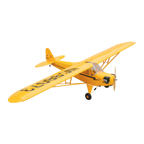
Piper J-3 Cub
Specifications
Wingspan: ....................................... 80" (2032mm)
Fuselage length: ........................... 49.9" (1268mm)
Wing area: ........................ 919 sq. in. (59.3 sq dm)
ASSEMBLY MANUAL
Weight: ............................ 6.75–7.5 lbs (3–3.4 kg)
Engine: ............ .36–.46 2-stroke, .56–.82 4-stroke
Radio: ................................. 4-channel w/ 5 servos
�
��
40
Advertisement
Table of Contents

Related Manuals for Hangar 9 Piper J-3 Cub 40


Summary of Contents for Hangar 9 Piper J-3 Cub 40
- Page 1 � �� Piper J-3 Cub ASSEMBLY MANUAL Specifications Wingspan: ........80" (2032mm) Weight: ......6.75–7.5 lbs (3–3.4 kg) Fuselage length: ......49.9" (1268mm) Engine: .... .36–.46 2-stroke, .56–.82 4-stroke Wing area: ......919 sq. in. (59.3 sq dm) Radio: ......... 4-channel w/ 5 servos...
-
Page 2: Table Of Contents
Table of Contents Contents of Kit ..............3 Additional Required Equipment. -
Page 3: Contents Of Kit
Contents of Kit Large Parts: A. Fuselage HAN4002 B. Wing HAN4001 C. Cowling HAN4004 D. Tail Set HAN4003 E. Landing Gear HAN4005 F. Wing Strut Set HAN4010 G. Window Set HAN4008 Items Not Shown: Fuel Tank Tail Wheel Assembly HAN4007 Decal Set HAN4009 Pushrod Set... -
Page 4: Additional Required Tools And Adhesives
Additional Required Tools and Adhesives Tools Adhesives • Adjustable wrench • 6-minute epoxy • Crimping tool • Thin CA • Drill • Medium CA • Drill bit: 1/16”, 5/64”, 3/32” Other Required Items • Felt-tipped pen • Epoxy brushes • Heat gun •... -
Page 5: Using The Manual
Using the Manual This manual is divided into sections to help make assembly easier to understand, and to provide breaks between each major section. Remember to take your time and follow the directions. Before Starting Assembly Before beginning the assembly of your J-3 Cub, remove each part from its bag for inspection. Closely inspect the fuselage, wing panels, rudder, and stabilizer and for damage. -
Page 6: Section 1: Hinge Installation
Section 1: Hinge Installation Required Parts Step 3 • Stabilizer • Elevator Place the hinges in the stabilizer. • Fuselage • Rudder • Wing • Aileron (R&L) • Tail gear wire • Hinge (17) Required Tools and Adhesives •... - Page 7 Section 1: Hinge Installation Step 6 Step 9 After the CA has cured, flex the surfaces several times to Coat the tail gear wire near the bushing with petroleum break in the hinges. jelly. Work the lubricant into the bearing to prevent epoxy from entering the bearing, gluing the bearing to the wire.
- Page 8 Section 1: Hinge Installation Step 11 Step 13 Cut a groove from the hole to the bottom of the rudder to Cut a slot in the end of the fuselage to accept the tail allow clearance for the tail gear bearing. gear bearing.
-
Page 9: Section 2: Engine Installation
Section 2: Engine Installation Required Parts Step 2 • Fuselage assembly • Fuel tank assembly Position the engine so the drive washer is 4 " • Engine mount forward of the firewall. Use the engine mount plates, 8-32 x 1" bolts, 8-32 lock nuts and #8 washers to attach •... - Page 10 Section 2: Engine Installation Step 4 Step 7 Attach the muffler to the engine using the hardware Attach the vent line to the muffler and the line from the provided with your particular engine. clunk to the carburetor. Note: It may be necessary to rotate the end of ...
-
Page 11: Section 3: Servo Installation (Aileron)
Section 3: Servo Installation (Aileron) Required Parts Step 2 • Wing (L&R) • Servo hatch (L&R) Install the recommended servo hardware (grommets and • #2 x 3/8" screw (8) • Control horn (2) eyelets) supplied with the servo. Temporarily install a long half servo arm (JRPA212) onto the servo and position •... - Page 12 Section 3: Servo Installation (Aileron) Step 4 Step 6 Place the aileron servo between the mounting blocks and Connect a 12" Servo Lead Extension (JRPA098) to the use a felt-tipped pen to mark the location of the four servo servo lead.
- Page 13 Section 3: Servo Installation (Aileron) Step 7 Step 8 Tie a wheel collar onto a piece of string. Drop the wheel Tie the string onto the servo extension. Gently pull the collar into the wing from the root and retrieve it from the extension through the wing using the string.
- Page 14 Section 3: Servo Installation (Aileron) Step 10 Step 12 Place a clevis retainer onto a clevis. Thread the clevis Drill the locations marked in the previous step using onto a 4 " pushrod wire. Remove the backplate a 3/32" drill bit. from a control horn, and then attach the clevis to the control horn.
-
Page 15: Section 4: Servo Installation (Fuselage)
Section 3: Servo Installation (Aileron) Step 14 Step 15 Plug in the aileron servo to the radio system. Center the Bend the pushrod wire at the mark. Use a pushrod wire trims on the transmitter to center the aileron servo. Hold keeper to secure the pushrod wire to the servo arm. - Page 16 Section 4: Servo Installation (Fuselage) Step 2 Step 5 Slide the wing strut mount into the opening. Secure the Place a clevis retainer onto a clevis. Thread the clevis mount using two #4 x 3/8" screws. onto a 32" pushrod wire. Remove the backplate from a control horn, and then attach the clevis to the control horn.
- Page 17 Section 4: Servo Installation (Fuselage) Step 7 Step 9 Plug in the rudder servo to the radio system. Center the Center the throttle stick and trim with both the receiver trims on the transmitter to center the rudder servo. Hold and transmitter on.
- Page 18 Section 4: Servo Installation (Fuselage) Step 11 Step 14 Remove the pushrod wire from the fuselage and remove Cut a groove into the pushrod from the hole to the end the clevis. Bend the pushrod wire at the mark. Slide of the pushrod.
- Page 19 Section 4: Servo Installation (Fuselage) Step 17 Step 20 Slide the 2 " piece of heat shrink over the wires and Plug the necessary servo leads into the receiver. This dowel. Use a heat gun or lighter to shrink the tubing. Once includes the switch harness and battery leads as well.
-
Page 20: Section 5: Window Installation
Section 5: Window Installation Required Parts Step 3 • Side window (L&R) • Front windscreen Cut and fit the two supports to the fuselage. Use medium • Support (2) • Fuselage hatch CA to glue them into position. Required Tools and Adhesives •... -
Page 21: Section 6: Landing Gear Installation
Section 6: Landing Gear Installation Required Parts Step 2 • Landing gear Position the 3.35" (85mm) wheel onto the inner hub. • 3.35" (85mm) wheel (2) • Wheel cap (2) Attach the outer wheel hub to the inner wheel hub using four 2mm x 14mm screws. - Page 22 Section 6: Landing Gear Installation Step 5 Position the landing gear to the bottom of the fuselage. Secure the position of the gear using four landing gear straps and eight 3mm x 10mm screws. Step 6 Secure the tail wheel using the small wheel collar and setscrew.
-
Page 23: Section 7: Installing The Stabilizer
Section 7: Installing the Stabilizer Required Parts Step 2 • Stabilizer assembly • Fuselage Attach a control horn to one of the elevator clevises. Line • #4 washer (4) • #2 washer (3) the holes in the control horn with the hinge line and mark the location for the mounting crews onto the elevator. - Page 24 Section 7: Installing the Stabilizer Step 4 Step 8 Repeat Steps 2 and 3 for the remaining elevator Attach the small brass fitting to the fin and stabilizer control horn. using 2-56 x 1/2" screws, #2 washers and 2-56 nuts. Fittings are placed on both sides of the rudder and ...
- Page 25 Section 7: Installing the Stabilizer Step 10 Step 11 Cut the cable into four equal pieces. Prepare one cable by Attach the four connectors to the brass fittings sliding the cable through a crimp, through the cable end, of the stabilizer.
-
Page 26: Section 8: Cowling Installation
Section 8: Cowling Installation Required Parts Step 3 • Fuselage • Propeller Remove the engine and slide the cowling onto the • #2 x 3/8" sheet metal screw (4) fuselage. Position it so the opening for the crankshaft is "... - Page 27 Section 8: Cowling Installation Step 5 Step 6 Drill 1/16" holes through the cowl and into the fuselage Attach the propeller following the instructions provided sides at the locations marked in the last step. Enlarge the with your particular engine. holes in the cowl using a 5/64"...
-
Page 28: Section 9: Wing Installation
Section 9: Wing Installation Required Parts Step 2 • Wing • Fuselage Thread the strut support anchors into the holes in the • 4-40 lock nut (16) • 4-40 nut (4) wing. The anchors have external threads. • Strut support anchor (4) •... - Page 29 Section 9: Wing Installation Step 4 Thread a 4-40 nut onto the threaded end of the strut. Thread a strut end onto the strut. The nut will be used once the strut has been adjusted. Step 5 Photo ...
- Page 30 Section 9: Wing Installation Step 8 Step 9 Support the fuselage so the wing is not resting on the Repeat Steps 1 through 8 to install the remaining wing work surface. Adjust the strut end so it aligns with the panel and strut.
-
Page 31: Adjusting The Engine
Adjusting the Engine Step 1 Step 3 Completely read the instructions included with your Before you fly, be sure that your engine idles reliably, engine and follow the recommended break-in procedure. transitions and runs at all throttle settings. Only when this is achieved should any plane be considered ... -
Page 32: Recommended Cg
Recommended CG An important part of preparing the aircraft for flight is properly balancing the model. This is especially important when various engines are mounted. Caution: Do not inadvertently skip this step! The recommended Center of Gravity (CG) range for the Piper J-3 Cub is 3 "... -
Page 33: Range Testing The Radio
Range Testing the Radio Before each flying session, range-check your radio. This is accomplished by turning on your transmitter with the antenna collapsed. Turn on the radio in your airplane. With your airplane on the ground, you should be able to walk 30 paces away from your airplane and still have complete control of all functions. -
Page 34: 2005 Official Ama National Model Aircraft Safety Code
2005 Official AMA National Model Aircraft Safety Code GENERAL 7) I will not operate models with pyrotechnics (any device that explodes, burns, or propels a projectile 1) I will not fly my model aircraft in sanctioned of any kind) including, but not limited to, rockets, events, air shows or model flying demonstrations until explosive bombs dropped from models, smoke it has been proven to be airworthy by having been... - Page 35 2005 Official AMA National Model Aircraft Safety Code 5) Flying sites separated by three miles or more Organized RC Racing Event are considered safe from site-to site interference, 10) An RC racing event, whether or not an AMA Rule even when both sites use the same frequencies. Any Book event, is one in which model aircraft compete circumstances under three miles separation require in flight over a prescribed course with the objective of...
- Page 36 � �� © 2005 Horizon Hobby, Inc. 4105 Fieldstone Road Champaign, Illinois 61822 (877) 504-0233 horizonhobby.com 7902...
Need help?
Do you have a question about the Piper J-3 Cub 40 and is the answer not in the manual?
Questions and answers