Table of Contents
Advertisement
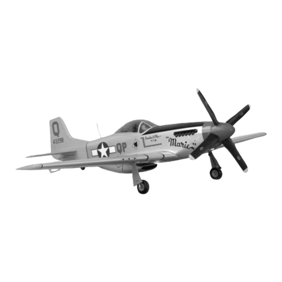
P-51 Mustang
Congratulations on your purchase of the Hangar 9
the modeler wanting to experience the thrill of being a Fighter Ace in the European Theater during WW-II. The Hangar 9
P-51 is a low-wing, high-performance plane. If this is your first attempt at flying this type of aircraft, please consult a
more experienced pilot to help in the setup and initial flights.
WE GET PEOPLE FLYING
1.50 ARF
ASSEMBLY MANUAL
®
P-51 Mustang ARF. This sport scale model warbird is intended for
TM
®
Specifications
Wingspan: .............. 77 in (1956mm)
Length: .................... 68 in (1727mm)
Wing Area:............. 1039 sq in (67.03sq dm)
Weight: ................... 13–14 lb (5.89–6.34 kg)
Engine:..................... 1.20–2.00 4-stroke
Radio: ...................... 6-channel w/10 servos
Advertisement
Table of Contents

Subscribe to Our Youtube Channel
Related Manuals for Hangar 9 P-51 Mustang 1.50 ARF


Summary of Contents for Hangar 9 P-51 Mustang 1.50 ARF
-
Page 1: Specifications
P-51 Mustang ARF. This sport scale model warbird is intended for the modeler wanting to experience the thrill of being a Fighter Ace in the European Theater during WW-II. The Hangar 9 P-51 is a low-wing, high-performance plane. If this is your first attempt at flying this type of aircraft, please consult a... -
Page 2: Table Of Contents
Table of Contents Table of Contents ............. . 2 Additional Required Equipment . -
Page 3: Additional Required Equipment
Contents of Kit Large Parts A. HAN2401 Wing Set with Joiner B. HAN2404 Fuselage C. HAN2402 Tail Set D. HAN2405 Fiberglass Belly Scoop E. HAN2406 Fiberglass Cowl F. HAN2407 Canopy Small Parts 1. HAN2403 Aluminum Stabilizer Tube Set 2. HAN2409 Tail Wheel Assembly 3. -
Page 4: Additional Required Tools And Adhesives
Additional Required Tools and Adhesives Tools Other Required Items • Drill • Mixing sticks for epoxy • Drill Bits: 1/16", 1/8", 3/32", 5/64”, 5/32" • Epoxy brushes • Phillips screwdriver (small, medium) • Rubbing alcohol • Pliers • Sanding bar •... -
Page 5: Warranty Information
Before Starting Assembly Before beginning the assembly of your P-51, remove each part from its bag for inspection. Closely inspect the fuselage, wing panels, rudder, and stabilizer for damage. If you find any damaged or missing parts, contact the place of purchase. If you find any wrinkles in the covering, use a heat gun or covering iron to remove them. -
Page 6: Section 1: Hinging The Ailerons
Section 1: Hinging the Ailerons Required Parts Step 3 • Right and left wing panels w/ailerons Slide the aileron onto the wing until there is only a slight gap between the aileron and wing panel. Remove • CA hinges (6) the T-pins and snug the aileron against the wing panel. - Page 7 Section 1: Hinging the Ailerons Step 5 Step 7 Turn the wing panel over, deflect the aileron in the Firmly grasp the wing and aileron and gently pull on opposite direction and apply thin CA to the other side the aileron to ensure the hinges are secure and cannot of the hinges as described in the previous step.
-
Page 8: Section 2: Aileron Servo Installation
Section 2: Aileron Servo Installation Required Parts Step 2 • Wing assembly Install the recommended servo hardware (grommets and eyelets) supplied with the servo. Temporarily install a • Aileron servos w/mounting hardware (2) long half servo arm (JRPA212) onto the servo and •... - Page 9 Section 2: Aileron Servo Installation Step 4 Photo for Step 5 Place the aileron servo between the mounting blocks and use a felt-tipped pen to mark the location of the four servo mounting screws. Note that the servo must not touch the hatch in order to isolate engine vibration.
- Page 10 Section 2: Aileron Servo Installation Step 7 Photo for Step 9 Use a piece of string with a small weight (such as a wheel collar) attached as a device to pull the servo lead through the wing. Lower the weight through the opening at the root of the wing as shown.
- Page 11 Section 2: Aileron Servo Installation Step 11 Photo for Step 11 Remove the servo hatch cover and re-drill the holes using a 5/64" drill bit. Use 2–3 drops of thin CA to harden the underlying wood. This will prevent the screws from crushing the wood when they are tightened.
-
Page 12: Section 3: Aileron Linkages
Section 3: Aileron Linkages Required Parts Step 3 • Wing assembly • Control horn (2) Remove the back plate from the control horn using side cutters or a sharp hobby knife. Use a 5/64" drill bit to drill • Mounting screws (6) •... - Page 13 Section 3: Aileron Linkages Step 5 Step 7 Drill three 1/16" holes at the locations marked in the Attach the control horn using three #2 x 3/8" screws. previous step. The holes only need to be 5/16" deep; don’t drill through the top of the aileron. Step 8 Step 6 Attach the aileron control linkage to the aileron...
-
Page 14: Section 4: Hinging The Flaps
Section 4: Hinging the Flaps Required Parts Step 3 • Wing assembly • Nylon flap hinges (6) Locate the holes in the wing and flap for the flap hinges. Remove the covering if necessary from each hole. There Required Tools and Adhesives will be a total of three holes each in the wing and flap. - Page 15 Section 4: Hinging the Flaps Step 4 Step 5 Install the hinges in the flap and slide the flap into Use 30-minute epoxy to install the hinges. Apply epoxy position. Check to make sure the flap aligns with to both the holes in the flap and wing using a toothpick. both the aileron and wing trailing edge.
-
Page 16: Section 5: Flap Servo Installation
Section 5: Flap Servo Installation Required Parts Step 2 • Wing assembly Install the recommended servo hardware (grommets and eyelets) supplied with the servo. Temporarily install a • Flap servos w/mounting hardware (2) long half servo arm (JRPA212) onto the servo and •... - Page 17 Section 5: Flap Servo Installation Step 3 Step 5 Locate the servo mounting blocks. Use 6-minute Remove the servo and use a 1/16" drill bit to predrill epoxyto glue them in place on the marks made in the holes for the servo mounting screws marked in the the previous step.
- Page 18 Section 5: Flap Servo Installation Step 7 Step 9 Connect a 6" Servo Lead extension (JRPA094) to the Stand the wing on the tip and allow the weight to drop servo lead. Secure the connectors by tying them in a through the wing until it appears in the opening for the knot using dental floss (as shown) or by using a servo leads.
- Page 19 Section 5: Flap Servo Installation Step 11 Step 12 Place the hatch cover into position in the flap opening. Remove the servo hatch cover and re-drill the holes using Measure in 1/8" on all four sides of the hatch. Drill four a 5/64"...
-
Page 20: Section 6: Flap Linkages
Section 6: Flap Linkages Required Parts Step 3 • Wing assembly • Control horn (2) Remove the back plate from the control horn using side cutters or a sharp hobby knife. Use a 5/64" drill bit to drill • Mounting screws (6) •... - Page 21 Section 6: Flap Linkages Step 5 Step 7 Drill three 1/16" holes at the locations marked in the Attach the control horn using three #2 x 3/8" screws. previous step. The holes only need to be 5/16" deep; don’t drill through the top of the flap. Step 8 Attach the flap control linkage to the flap control horn.
-
Page 22: Section 7: Retract Servo Installation
Note: The retract mechanism for the P-51 ® comes preinstalled from Hangar 9 . The P-51 retract system is designed to use low-profile retract servos, such as the JRPS703. - Page 23 Section 7: Retract Servo Installation Step 5 Step 8 Re-install the retract back into the wing. Guide the Using a ruler, locate a hole in the servo arm that is retract pushrod through the wing and into the opening 1/2” away from the center on the arm. Drill the hole for the retract servo.
-
Page 24: Section 8: Main Landing Gear And Wheel Doors
Section 7: Retract Servo Installation Step 11 With the retract servo in the retracted position, push the retract linkage to manually retract the landing gear. Install a 4-40 x 1/4" screw into the easy connector and tighten it to secure the retract linkage. Photo for Step 12 Photo for Step 12 Step 12... - Page 25 Section 8: Main Landing Gear and Wheel Fairings Step 2 Step 4 Slide the axle mount onto the landing gear strut. Apply a Slide a wheel collar onto the axle. Position the wheel drop of thread locking compound onto a 6-32 set screw. collar against the axle mount, and then secure its location Secure the axle mount using the 6-32 set screw, making using an M3 x 8 screw.
- Page 26 Section 8: Main Landing Gear and Wheel Fairings Step 7 Step 9 Check the fit of the wheel in the wheel well when the Draw two small marks on the landing gear door that will gear is retracted. Make any necessary adjustments so indicate the location of the landing gear strut.
- Page 27 Section 8: Main Landing Gear and Wheel Fairings Step 11 Photo for Step 14 Position the gear door mounts as follows: Position mount near the wheel so it is almost touching the wheel well. Position the mount near the retract mechanism slightly below the wheel well.
-
Page 28: Section 9: Joining The Wing
Section 8: Main Landing Gear and Wheel Fairings Step 17 Step 18 Once the landing gear door has been adjusted, move Apply a few drops of thick CA to the screws to prevent the retracts to the extended position. Apply a few drops them from loosening during flight. - Page 29 Section 9: Joining the Wing Step 3 Step 5 Locate the wing joiner and mark a centerline on the joiner. With the wing panels together, check for correct dihedral. Place the wing on a large flat surface with one panel resting flat on the surface. The opposite wing tip should be 7 "...
- Page 30 Section 9: Joining the Wing Step 7 Step 10 Completely coat one half of the wing joiner with epoxy up Apply epoxy to root wing rib of both panels. to the line drawn in Step 1. Be sure to apply epoxy to the top and bottom of the joiner also.
-
Page 31: Section 10: Mounting The Wing To The Fuselage
Section 10: Mounting the Wing to the Fuselage Required Parts Step 3 • Assembled wing • Fuselage Mix 1/2 ounce of 6-minute epoxy and coat both the wing and plywood plate. Align the plate back onto the wing and • Plywood wing bolt plate (2) clamp it in position. -
Page 32: Section 11: Lower Air Intake Installation
Section 11: Lower Air Intake Installation Required Parts Step 3 • Air scoop • Plastic guide tubes (2) Place a piece of wax paper between the fuselage and wing, then bolt the wing onto the fuselage. • Plywood tube locators (2) Required Tools and Adhesives •... - Page 33 Section 11: Lower Air Intake Installation Step 5 Step 7 Position the air scoop onto the wing bolt plates. It Remove the wing bolts from the plane by sliding them out should fit snug onto the plates. Remove the air scoop, through the tubes.
-
Page 34: Section 12: Stabilizer Installation
Section 11: Lower Air Intake Installation Step 9 Remove the excess tube using a razor saw and hobby knife. Section 12: Stabilizer Installation Required Parts Step 1 • Fuselage • Stabilizer (right and left) Locate both of the stabilizer tubes, short and long. Slide the tubes into one half of the stabilizer as follows: short •... - Page 35 Section 12: Stabilizer Installation Step 2 Step 4 Slide the tubes into the fuselage. The hole in the stabilizer Use a 3/32" drill bit to drill through the hole in the faces the bottom of the plane. stabilizer into the stabilizer tube. Be very careful to only drill through the tube, not through the top of the stabilizer.
-
Page 36: Section 13: Hinging The Elevators
Section 13: Hinging the Elevators Required Parts Step 3 • Stabilizer • Elevator (right and left) Slide the elevator onto the stabilizer until there is only a slight gap between the stabilizer and elevator. Remove • CA hinges (6) the T-pins and snug the elevator against the stabilizer. Required Tools and Adhesives Position the elevator so the tip aligns with the tip •... - Page 37 Section 13: Hinging the Elevators Step 5 Step 7 Turn the fuselage over, deflect the elevator in the Firmly grasp the elevator and stabilizer and gently pull opposite direction, and apply thin CA to the other them apart to ensure the hinges are secure and cannot be side of the hinges as described in the previous step.
-
Page 38: Section 14: Hinging The Rudder
Section 14: Hinging the Rudder Required Parts Step 2 • Fuselage assembly • Rudder Slide the rudder onto the fin. Align the top of the rudder with the top of the fin. Remove the T-pins and use • CA hinges (3) thin CA to glue the hinges into position. -
Page 39: Section 15: Tail Wheel Installation
Section 15: Tail Wheel Installation Required Parts Step 2 • Pushrod wire (33-5/8" long) File a flat spot on the tail gear wire. Position the flat off-center slightly as shown in the photo. • Nylon clevis • Clevis keeper • Wheel collar (2) •... - Page 40 Section 15: Tail Wheel Installation Step 4 Step 7 Slide a clevis keeper onto a nylon clevis. Thread the Position the steering arm in the center of the clevis onto the wire a minimum of 10 turns. pre-installed tail gear mount. Make sure the set screw in the arm is facing forward.
-
Page 41: Section 16: Fuel Tank Assembly
Section 15: Tail Wheel Installation Step 9 Step 10 Slide a wheel collar onto the tail gear wire, then the tail Secure the tail gear door cover using four wheel. Finally, slide another wheel collar on, and use an #2 x 3/8" screws. M3 x 8 screw to secure the outer collar. - Page 42 Section 16: Fuel Tank Assembly Step 2 Step 5 Locate the rubber stopper. Insert the shorter metal fuel Slide the vent tube into on of the remaining two holes in tube into one of the holes in the stopper so that an the stopper from the tank (small cap) side.
- Page 43 Section 16: Fuel Tank Assembly Step 7 Step 8 Carefully insert the stopper assembly into the fuel tank. Tighten the M3 x 20 screw carefully—do not over tighten. Note the position of the vent tube; it must be up at the top This allows the rubber stopper to form a seal by being portion of the fuel tank to function properly.
-
Page 44: Section 17A: Engine Installation (Saito 180Gk)
Section 17A: Engine Installation (Saito 180GK) Required Parts Step 1 • Fuselage • Engine mount (2) Locate the engine mount and the associated hardware. • #8 washers (8) • Engine • 8-32 x 1 " screws (8) • 8-32 nylon lock nuts (4) •... - Page 45 Section 17A: Engine Installation (Saito 180GK) Step 3 Step 5 Prepare the engine mount for installation by sliding Install the spinner back plate and propeller. Position the four 8-32 bolts and washers through the engine engine so there is between 1/16" and 1/8" gap between mount.
-
Page 46: Section 17B: Engine Installation (Saito 200 Ti)
Section 17B: Engine Installation (Saito 200 TI) Required Parts Step 2 • Fuselage • Engine If you must remove the blind nuts, thread an 8-32 bolt partially into the nut. Lightly tap the bolt to pop the blind • #8 washers (4) •... - Page 47 Section 17B: Engine Installation (Saito 200 TI) Important: The stock engine mount is offset Step 6 1/4" towards the top of the fuselage. Measure Transfer the measurements made in the last step to 1/4" towards the bottom of the fuse and make the firewall.
- Page 48 Section 17B: Engine Installation (Saito 200 TI) Step 7 Step 9 Drill the locations for the new bolts using a 1/4" drill bit. Install any accessories that may be required for your particular engine. In the case of the Saito 200TI, a needed valve must be attached to the mount.
-
Page 49: Section 18: Throttle Pushrod And Fuel Tank
Section 18: Throttle Pushrod and Fuel Tank Required Parts Step 2 • Fuel tank assembly • Foam: 1/4", 1/2" Test fit the throttle pushrod tube through the firewalland into the fuselage. Once satisfied with the fit, mix1/4 ounce • Throttle pushrod tube (15") of 6-minute epoxy and glue the pushrodinto the firewall. - Page 50 Section 18: Throttle Pushrod and Fuel Tank Step 4 Step 6 Install the throttle pushrod into the tube and connect it to Connect the two pieces of fuel tubing to the fuel tanks the throttle arm. You may need to remove the throttle pickup and vent tubes.
-
Page 51: Section 19: Radio Installation
Section 19: Radio Installation Required Parts Note: Place a drop of thin CA onto each screw hole to harden the wood around the • Fuselage assembly • Foam hole. Allow the CA to fully cure before • Receiver • Receiver battery installing the servos. - Page 52 Section 19: Radio Installation Step 5 Step 7 Connect any necessary extensions and Y-harnesses Wrap the receiver battery in protective foam as you did necessary to connect up the retract, aileron and flap the receiver. Temporarily mount the receiver and battery servos.
-
Page 53: Section 20: Rudder And Elevator Linkages
Section 20: Rudder and Elevator Linkages Required Parts Step 2 • Fuselage assembly • Pushrod wires (3) Slide a clevis keeper onto a nylon clevis. Thread the clevis onto the wire a minimum of 10 turns. Repeat this • Nylon clevis (3) •... - Page 54 Section 20: Rudder and Elevator Linkages Step 4 Step 6 Attach the clevis to the control horn. Position the control Install one of the #2 x 3/8" screws in a hole drilled, horn on the elevator so the control rod is straight, and then remove it.
- Page 55 Section 20: Rudder and Elevator Linkages Step 11 Slide the wire through the outer hole in the elevator servo arm. Secure the wire using a nylon wire keeper. Photo for Step 8 Step 9 Bend the wire 90 degrees at the mark made in Step 12 the previous step Repeat Steps 3 through 11 for the remaining elevator half.
- Page 56 Section 20: Rudder and Elevator Linkages Step 17 Photo for Step 20 Remove the back plate from the last control horn using side cutters or a sharp hobby knife. Step 18 Attach the clevis to the control horn. Position the control horn on the rudder so the control rod is straight, and the front edge of the control horn aligns with the front edge of the bevel on the rudder.
-
Page 57: Section 21: Throttle Linkage Installation
Section 21: Throttle Linkage Installation Required Parts Step 3 • Easy connector • M3 x 8 screw Move the throttle stick and trim to low. Check to make sure the carburetor will move to the low position when • Connector back plate operating the servo. -
Page 58: Section 22: Attaching The Cowl
Section 22: Attaching the Cowl Required Parts Note: If you are using the Saito 200TI, it will be required to install a baffle inside the cowl to • Fuselage assembly • Cowl direct air over the rear cylinder. Make the baffle •... - Page 59 Section 23: Cockpit Details Step 2 Step 4 Cut out the instrument panel decal and apply. Glue the clear gun site into position using 6-minute epoxy. Step 5 Glue the exhaust into position using Shoe Goo. Step 3 Glue the cockpit details to the fuselage using Shoe Goo or similar type adhesive, using the pictures on thebox as a guide.
-
Page 60: Section 25: Applying The Decals
Section 24: Attaching the Canopy Required Parts Step 1 • Fuselage assembly Glue the canopy to the fuselage using RC560 canopy glue. Tape the canopy in place with masking tape and • Canopy allow the glue to cure overnight. Required Tools and Adhesives •... -
Page 61: Adjusting The Engine
Control Throws and Center of Gravity Recommended CG Location The following control throws offer a good place to start with your first flights. We recommend only one rate An important part of preparing the aircraft for flight is setting for the P-51. As you become more familiar with properly balancing the model. - Page 62 2003 Official AMA National Model Aircraft Safety Code Effective January 1, 2003 Model Flying MUST be in accordance with this Code in order for AMA Liability Protection to apply. GENERAL 7) I will not operate models with pyrotechnics (any device that explodes, burns, or propels a projectile of any kind) 1) I will not fly my model aircraft in sanctioned events, air including, but not limited to, rockets, explosive bombs...
- Page 63 2003 Official AMA National Model Aircraft Safety Code Continued 4) I will operate my model using only radio control Organized RC Racing Event frequencies currently allowed by the Federal 10) An RC racing event, whether or not an AMA Rule Communications Commission.
- Page 64 ® WE GET PEOPLE FLYING © 2003, Horizon Hobby, Inc. 4105 Fieldstone Road Champaign, Illinois 61822 (217) 355-9511 www.horizonhobby.com # 5768...
Need help?
Do you have a question about the P-51 Mustang 1.50 ARF and is the answer not in the manual?
Questions and answers