Table of Contents
Advertisement
TM
®
WE GET PEOPLE FLYING
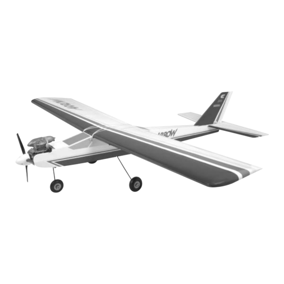
Semi-Symmetrical Trainer
INSTRUCTION MANUAL
Specifications
Wingspan: . . . . . . . 63 in (1600mm)
Length: . . . . . . . . 52.5 in (1334mm)
Wing Area: . 710 sq in (45.8 sq dm)
Weight: . . . . . . . . . . . 5.7 lb (2.6 kg)
Featuring the Unique Evolution Trainer Power System
The Evolution Trainer
Power System.
Engineered for ease...
first flight, every flight.
Advertisement
Table of Contents

Subscribe to Our Youtube Channel
Summary of Contents for Hangar 9 ARROW
- Page 1 ® WE GET PEOPLE FLYING Semi-Symmetrical Trainer INSTRUCTION MANUAL Specifications Wingspan: ..63 in (1600mm) Length: ..52.5 in (1334mm) Featuring the Unique Evolution Trainer Power System Wing Area: .
- Page 2 Tape Strip Section 1. Assemble Wing Section 2. Mount Main Landing Gear Wood Screws...
-
Page 3: Assembly Diagram
Section 3. Bolt on Tail Large Washers Small Washers Long Screws Rubber Bands (4 per side to hold wing) Assembly Diagram Please carefully read through the entire instruction manual before beginning assembly of the Arrow Semi-Symmetrical Trainer Ready-To-Fly (RTF) kit. -
Page 4: Table Of Contents
Flying the Arrow Advanced Trainer ........ -
Page 5: Section 1: Assembly Of The Wing
The The aileron servo lead has been wrapped around the linkage for hinges in the Arrow Trainer have already been glued in place during shipment. Untie the servo lead to free up the aileron linkage. -
Page 6: Section 2: Installing The Main Landing Gear/Wing Hold-Down Dowels
Section 2: Installing the Main Landing Gear/Wing Hold-Down Dowels Wood Screw (4) Landing Gear Strap (2) Step 1 Mount landing gear to fuselage with the two straps and four screws. Step 2 Step 1 Step 2 Locate the two landing gear wires, two nylon landing gear straps With the landing gear wires installed, secure them to the fuselage and the four 3mm x 10mm sheet metal screws. -
Page 7: Section 3: Installing The Tail Assembly
Section 3: Installing the Tail Assembly Locate the horizontal stabilizer and vertical stabilizer assemblies. Step 2 The rudder and elevator have been prehinged at the factory, and Slide the tail assembly into the slot in the rear of the fuselage, the control horns are also attached. -
Page 8: Final Assembly
For now, use two rubber bands to mount the wing in position. Center of Gravity (CG) The Arrow Trainer has been balanced at the factory. gravity) of the Arrow is 3 " from the leading edge of the wing. If... -
Page 9: Control Checks
Control Checks The correct servo directions are preadjusted, but it’ s a good idea Throttle: Look into the to confirm the correct direction. After charging the transmitter and carburetor. With the throttle receiver batteries per the instruction included with the radio, turn (left stick) in the up position, on the transmitter and airplane and check that the controls are the carburetor should be fully... -
Page 10: Evolution Trainer Power System
• Only make adjustments to the carburetor from behind the engine. with the first time pilot in mind. The engine and special three blade propeller have been designed to give your Arrow Trainer the optimum performance for training new RC pilots. The engine is designed for easy starting and reliable idle to give you confidence in... -
Page 11: Starting The Evolution Engine
Starting the Evolution Engine Field Equipment Needed Step 2 The following are included in the Hangar 9 ® Start-Up Field To prime your engine, first turn on your transmitter and then your Accessory Pack (HANSTART) receiver. Move the throttle to full open and place your finger over •... -
Page 12: Engine Adjustments
At full throttle, the fly your Arrow Trainer, and then give you your first chance on the Arrow Trainer is more than capable of most Sport “sticks”... -
Page 13: Ama Safety Code
AMA Safety Code 1994 Official AMA National Model Aircraft Safety Code Effective January 1, 2003 Model Flying MUST be in accordance with this Code in order for AMA Liability Protection to apply. GENERAL RADIO CONTROL 1) I will not fly my model aircraft in sanctioned events, air 1) I will have completed a successful radio equipment ground shows or model flying demonstrations until it has been proven range check before the first flight of a new or repaired model. -
Page 14: Glossary Of Terms
(This has already • Clevis: The clevis connects the wire end of the pushrod to the been done for you on the Arrow Advanced trainer.) control horn of the control surface. A small clip, the clevis has •... - Page 15 • Roll Axis: The horizontal plane on which the airplane’ s wings • Torque Rods: Inserted into the ailerons, these rigid wire rods are raised or lowered. By adjusting the ailerons, you can drop a run along the wing’ s trailing edge, then bend downward and wing tip below the roll axis and cause the airplane to bank or roll.
- Page 16 ® WE GET PEOPLE FLYING © 2003, Horizon Hobby, Inc. 4105 Fieldstone Road Champaign, Illinois 61822 (217) 355-9511 www.horizonhobby.com 5937...


Need help?
Do you have a question about the ARROW and is the answer not in the manual?
Questions and answers