Sign In
Upload
Manuals
Brands
Ricoh Manuals
Copier
Grand Kingfisher A245
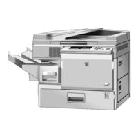
Ricoh Grand Kingfisher A245 Manuals
Manuals and User Guides for Ricoh Grand Kingfisher A245. We have
2
Ricoh Grand Kingfisher A245 manuals available for free PDF download: Service Manual
Ricoh Grand Kingfisher A245 Service Manual (373 pages)
Brand:
Ricoh
| Category:
Copier
| Size: 9.67 MB
Table of Contents
Table of Contents
13
Overall Machine Information
28
Specifications
30
Copy Process Around the Drum
33
Mechanical Component Layout
35
Drive Layout
36
Paper Path
37
Electrical Component Descriptions
38
Detailed Descriptions
42
Drum
44
Opc Drum Characteristics
44
Drive Mechanism
45
Charge
46
Overview
46
Charge Corona Wire Cleaner Mechanism
47
Charge Corona Circuit
48
Optics
49
Overview
49
Scanner Drive
50
Lens Drive
51
4Th/5Th Mirror Drive
52
Automatic Image Density Sensor
53
Exposure Lamp Voltage Control
54
Erase
58
Overview
58
Lead Edge Erase
59
Side Erase
59
Trailing Edge Erase
60
Development
61
Overview
61
Drive Mechanism
62
Cross-Mixing
63
Development Bias for Image Density Control
64
Base Bias Voltage Factor in Manual Image Density Mode
65
Base Bias Voltage Factor in Automatic Image Density (ADS) Mode
66
Drum Residual Voltage
66
R ) Correction Factor
66
Development Bias Circuit
67
Toner Supply
68
Toner Bottle Replenishment Mechanism
68
Toner Supply Mechanism
69
Toner Density Detection Mechanism
70
Td Sensor Check and Toner Supply Timing
71
Toner Supply Control
72
Modes Available
72
Detect Supply Mode
72
Fixed Supply Mode
75
Abnormal Condition in Toner Density Detection
75
Toner End
76
Toner Near End
76
Toner End Recovery
77
Image Transfer and Paper Separation
78
Overall
78
Transfer Corona and Discharge Plate Circuit
79
Drum Cleaning
80
Overview
80
Toner Recycling Mechanism
81
Quenching
82
Paper Feed and Registration
83
Overview
83
Paper Tray Feed
84
Paper Lift Mechanism
84
Paper Feed Mechanism
85
By-Pass Feed
86
Overview
86
Paper Feed Mechanism and Paper End Detection
87
Paper Registration
88
Side Fence Double Stopper Mechanism
89
Paper End Detection
90
Paper Feed and Misfeed Detection Timing
91
Others
92
Paper Size Detection
92
Shock Absorber
92
Image Fusing
93
Overview
93
Fusing Drive Mechanism
94
Fusing Lamp Control
95
Fusing Lamp Control Circuit
97
Overview
97
On/Off Control
98
Phase Control Mode
98
Overheat Protection
99
Installation
100
Installation Requirements
102
Environment
102
Machine Level
102
Minimum Space Requirements
103
Power Requirements
103
Copier (A219)
104
Accessory Check
104
Installation Procedure
105
Document Feeder (A662)
109
Accessory Check
109
Installation Procedure
110
Sorter (A657)
113
Accessory Check
113
Installation Procedure
114
Others
117
Optics Anti-Condensation Heater Installation (Option)
117
Tray Heater Installation (Option)
119
Service Tables
120
Service Remarks
122
General Cautions
122
Imaging Unit
122
Optics
123
Transfer Corona
124
Fusing Unit
124
Paper Feed
125
Others
125
Program Modes
127
Basic Operation
127
Sp Mode
128
Sp Mode Quick Reference Table
129
Up Mode and Sp Mode Cross Reference Table
130
Service Program Mode Table
131
Clear All Memory Procedure
145
Practical Sp Mode Use Table
147
Service Tables
148
TEST POINTS (Main Control Board)
148
Variable Resistors
148
Preventive Maintenance
150
Preventive Maintenance Schedule
152
Pm Table
152
Regular Pm Procedure
155
Special Tools and Lubricants
158
Replacement and Adjustment
160
Exterior and Inner Covers
162
Exterior Cover Removal
162
Front Cover
162
Front Right Cover
162
Rear Right Cover
162
Lower Right Cover
163
Lower Left Cover
163
Upper Left Cover
163
Rear Cover
163
Upper Cover
164
Inner Cover Removal
165
Optics
166
Exposure Glass Removal
166
1St Scanner/Exposure Lamp Removal
167
Scanner Belt Removal
169
1St and 2Nd Scanner Position Adjustment
170
Scanner Drive Motor Removal
171
Lens Drive Motor Removal
172
4Th/5Th Mirror Drive Motor Removal
173
2Nd Mirror Replacement
174
3Rd Mirror Replacement
175
4Th and 5Th Mirror Replacement
176
Ads Sensor Replacement
178
Around the Drum
179
Imaging Unit Removal and Toner Bottle Removal
179
Charge Corona Wire and Charge Corona Grid Replacement
180
Cleaning Blade Replacement
181
Drum Replacement
182
Toner Collection Coil and Toner Recycling Belt Replacement
183
Developer Replacement
184
Replacement the Toner Density Sensor (Td Sensor)
185
Agitator Replacement
186
Toner Supply Motor Ass'y Replacement
187
Erase Lamp Replacement
188
Quenching Lamp Replacement
189
Paper Feed
190
Paper Tray Removal
190
Tray Feed Roller Replacement
191
Tray Paper Feed Roller Adjustment
192
By-Pass Feed Roller and Friction Pad Replacement
193
By-Pass Paper Feed Clutch, High Voltage Supply Board, and Registration Clutch Replacement
195
Right Vertical Guide Switch Replacement
196
Relay Roller Clutch and Paper Feed Clutch Replacement
197
Paper Size Switch Replacement
198
By-Pass Paper End Sensor and Registration Sensor Replacement
199
Fusing
200
Fusing Unit Removal
200
Hot Roller Replacement
201
Pressure Roller Replacement
202
Hot Roller Stripper Replacement
203
Fusing Entrance Guide Adjustment
204
Fusing Pressure Adjustment
205
Transfer/Separation
206
Transfer Corona Wire Replacement
206
Discharge Plate Replacement
207
Others
208
Ozone Filter Replacement
208
Main Control Board Replacement
209
Copy Quality Adjustment
210
Light Intensity Adjustment
211
Base Exposure Lamp Voltage Adjustment
211
Image Density Adjustment
212
Development Bias Voltage Adjustment
213
Base Bias Voltage Adjustment
213
SP Bias Settings
214
Toner Density Adjustment
215
Toner Supply Ratio Selection
215
Grid Voltage Adjustment
216
Transfer Current Adjustment
217
Charge Current Adjustment
218
Horizontal Magnification Adjustment
219
Vertical Magnification Adjustment
219
Focus Adjustment
220
Leading Edge Erase Margin Adjustment
220
Registration Adjustment
220
4Th/5Th Mirror Height Adjustment
221
ADS (Auto Image Density Sensor) ADJUSTMENT
222
Side-To -Side Registration Adjustment
223
Troubleshooting
226
Copy Quality
228
Blank Copy (White Copy)
228
Dirty Background
230
Uneven Image Density
232
Vertical Black Bands
233
Vertical Black Lines
234
Vertical White Lines or Bands-1 (Dull or Blurred)
235
Vertical White Lines or Bands-2 (Thin, Distinct)
236
Horizontal Black/White Lines
237
Jitter
238
Black Spots on the Copy Image
239
Skewed (Optical) Copy Image
240
Toner Density on Copies too High
241
Toner Density on Copies too Low
243
Unfused Copy Image
245
Creasing Paper after Fusing
246
Paper Misfeed
247
Abnormal Condition in Toner Density Detection
248
Service Call Conditions
250
Electrical Component Defects
256
Sensors
256
Switches
257
Blown Fuse Conditions
258
User Codes
258
Document Feeder A662
260
Document Feeder (A662)
260
Specifications
262
Component Layout
263
Mechanical Components
263
Electrical Components
263
Electrical Component Descriptions
264
Power Distribution
265
Basic Operation
266
Interface Circuit
267
Original Feed
268
Original Pick-Up Mechanism
268
Original Separation Mechanism
269
Original Feed-In Mechanism
270
Original Feed-Out Mechanism
271
Df Motor Circuit
272
Original Feed and Misfeed Detection Timing
273
Service Tables
274
Dip Switches
274
Variable Resistors
274
Fuse
274
Replacement and Adjustment
275
Transport Belt Replacement
275
Feed-In Unit Removal
277
Pick-Up Roller Replacement
278
Feed Roller Replacement
279
Friction Belt Replacement
280
Pick-Up Solenoid Adjustment
281
Sorter A657
282
Specifications
284
Component Layout
285
Electrical Component Descriptions
286
Basic Operation
287
Exit Roller Drive Mechanism
288
Bin Drive Mechanism
289
Misfeed Detection
291
Service Tables
291
Fuse
291
Preparation for Transportation
292
Roller Drive Belt Replacement
293
Bin Guide Lubrication
294
Appendix
296
Timing Chart
296
A245 Service Manual
306
Specifications
308
Mechanical Component Layout
311
Drive Lauout
312
Paper Path
313
Electrical Component Descriptions
314
Paper Feed
317
Overview
317
Paper Lift Mechanism
318
Paper Feed and Drive Mechanism
319
Paper Feed and Misfeed Detection Timing
320
Image Fusing
321
Installation
322
Copier Accessory Check
322
Copier Installation Procedure
323
Upper and Lower Tray Heater Installation (Option)
327
Program Mode
329
Sp Mode Quick Reference Table
329
Up Mode and Sp Mode Cross Reference Table
330
Service Program Mode Table
331
Preventive Maintenance Schedule
346
Modifies Pm Table
346
Replacement and Adjustment
352
Paper Feed Roller Replacement
352
Relay Roller Clutch and Paper Feed Clutch Replacement
353
Paper Size Switch Replacement
354
Paper End Sensors
355
12 Regular Pm Procedure
356
Service Call Conditions
356
B019 Service Manual
368
Specifications
368
Electrical Components Description
369
Installation Procedures
369
Copier Accessory Check List
369
Service Tables
369
Service Program Modes
369
Pm Table
373
Advertisement
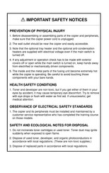
Ricoh Grand Kingfisher A245 Service Manual (62 pages)
Brand:
Ricoh
| Category:
All in One Printer
| Size: 0.86 MB
Table of Contents
Specifications
3
Mechanical Component Layout
6
Drive Layout
7
Paper Path
8
Electrical Component Descriptions
9
Paper Feed
12
Paper Lift Mechanism
13
Paper Feed and Misfeed Detection Timing
15
Image Fusing
16
Hot Roller
16
Pressure Roller
16
Installation
17
Copier Installation Procedure
18
Lower Tray
22
Program Mode
24
Service Program Mode Table
26
Preventive Maintenance Schedule
41
Replacement and Adjustment
44
Paper Feed Roller Replacement
44
Paper Size Switch Replacement
46
Paper End Sensors
47
Regular Pm Procedure
48
Service Call Conditions
51
Advertisement
Related Products
Ricoh A251
Ricoh A219
Ricoh A252
Ricoh A220
Ricoh A217
Ricoh A229
Ricoh A076-15
Ricoh A077-26
Ricoh Aficio A080
Ricoh AO40
Ricoh Categories
All in One Printer
Printer
Digital Camera
Copier
Printer Accessories
More Ricoh Manuals
Login
Sign In
OR
Sign in with Facebook
Sign in with Google
Upload manual
Upload from disk
Upload from URL