Sign In
Upload
Manuals
Brands
Omron Manuals
Control Unit
CS1W-DRM21
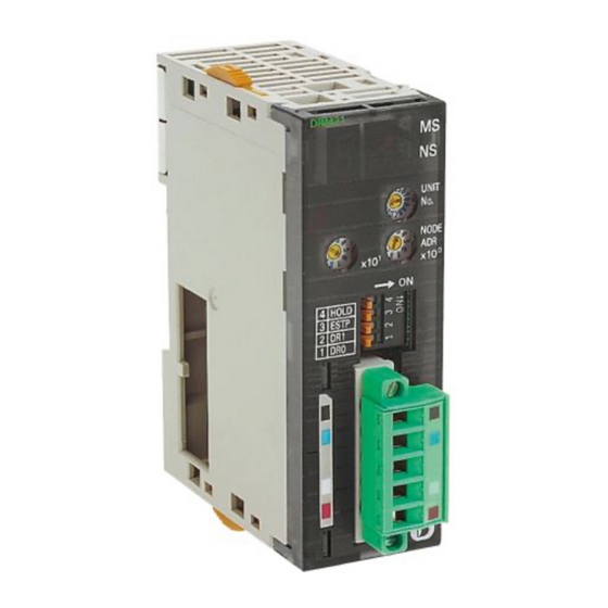
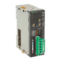
Omron CS1W-DRM21 Manuals
Manuals and User Guides for Omron CS1W-DRM21. We have
2
Omron CS1W-DRM21 manuals available for free PDF download: Operation Manual
Omron CS1W-DRM21 Operation Manual (379 pages)
DeviceNet Slaves
Brand:
Omron
| Category:
Network Hardware
| Size: 6.69 MB
Table of Contents
Precautions
12
Table of Contents
12
Intended Audience
13
General Precautions
13
Safety Precautions
13
Operating Environment Precautions
13
Application Precautions
14
EC Directives
15
Devicenet Manuals
16
Drt1-Id08-1
25
Drt1-Id16-1
25
Drt1-Od08
25
Drt1-Od08-1
25
Section 2 Example System Setup
30
Basic Procedures and Configuration Examples
31
Basic Procedures
31
System Configuration Example
32
Preparations
32
Setting and Wiring Hardware
33
Mounting and Setting the Master Unit
33
Mounting and Setting Slaves
34
Mounting Connecting Devices
35
Connecting Cables
36
Starting Communications
37
Creating I/O Tables for the Master Unit
37
Starting the System
37
Creating and Registering Scan Lists
38
Checking Operations
41
Indicator Status
41
Reading and Writing Data
41
Section 4 General-Purpose Slaves
48
Common Specifications for General-Purpose Slaves
50
Current Consumption and Weight
50
Connecting Communications Cables to General-Purpose Slaves
51
Connecting Communications Cables
51
Connecting Communications Cables to the Nodes
54
Mounting Terminating Resistors
56
Transistor Remote I/O Terminals
57
Node Address, Baud Rate, and Output Hold/Clear Settings
57
Transistor Remote Input Terminals with 8 Points: DRT1-ID08 (NPN) and DRT1-ID08-1 (PNP)
58
Transistor Remote Input Terminals with 16 Points: DRT1-ID16 (NPN) and DRT1-ID16-1 (PNP)
62
Transistor Remote Output Terminals with 8 Points: DRT1-OD08 (NPN) and DRT1-OD08-1 (PNP)
66
Transistor Remote Output Terminals with 16 Points: DRT1-OD16 (NPN) and DRT1-OD16-1 (PNP)
70
Drt1-Od16
70
Drt1-Od16-1
70
Transistor Remote I/O Terminal with 8 Inputs and 8 Outputs: DRT1-MD16 (NPN)
73
Drt1-Md16
73
Mounting in Control Panels
76
Wiring Internal Power Supplies, I/O Power Supplies, and I/O Lines
77
Transistor Remote I/O Terminals with 3-Tier I/O Terminal Blocks
79
Node Address, Baud Rate, and Output Hold/Clear Settings
79
Transistor Remote Input Terminals with 16 Points and 3-Tier I/O Terminal Blocks: DRT1-ID16T (NPN) and DRT1-ID16T-1 (PNP)
80
Drt1-Id16T Drt1-Id16T-1
80
Transistor Remote Input Terminals with 16 Points and 3-Tier I/O Terminal Blocks: DRT1-ID16TA (NPN) and DRT1-ID16TA-1 (PNP)
84
Transistor Remote Output Terminals with 16 Points and 3-Tier I/O Terminal Blocks: DRT1-OD16T (NPN) and DRT1-OD16T-1 (PNP)
87
Transistor Remote Output Terminals with 16 Points and 3-Tier I/O Terminal Blocks: DRT1-OD16TA (NPN) and DRT1-OD16TA-1 (PNP)
90
Transistor Remote I/O Terminals with 8 Inputs and 8 Outputs and 3-Tier I/O Terminal Blocks: DRT1-MD16T (NPN) and DRT1-MD16T-1 (PNP)
94
Transistor Remote I/O Terminals with 8 Inputs and 8 Outputs and 3-Tier I/O Terminal Blocks: DRT1-MD16TA (NPN) and DRT1-MD16TA-1 (PNP)
98
Mounting in Control Panels
102
Wiring Internal Power Supplies, I/O Power Supplies, and I/O Lines
103
Transistor Remote I/O Terminals with Connectors
104
Node Address, Baud Rate, and Output Hold/Clear Settings
104
Transistor Remote Input Terminals with 32 Points and Connectors
105
DRT1-ID32ML (NPN) and DRT1-ID32ML-1 (PNP)
105
Transistor Remote Output Terminals with 32 Points and Connectors
110
DRT1-OD32ML (NPN) and DRT1-OD32ML-1 (PNP)
110
Transistor Remote I/O Terminals with
111
DRT1-MD32ML (NPN) and DRT1-MD32ML-1 (PNP)
116
Mounting in Control Panels
120
Wiring Internal Power Supplies, I/O Power Supplies and I/O
125
Remote Adapters
128
Node Address, Baud Rate, and Output Hold/Clear Settings
128
Remote Input Adapters with 16 Points
129
DRT1-ID16X (NPN) and DRT1-ID16X-1 (PNP)
129
Remote Output Adapters with 16 Points
134
DRT1-OD16X (NPN) and DRT1-OD16X-1 (PNP)
134
Mounting in Control Panels
139
Wiring Internal Power Supplies, I/O Power Supplies, and I/O Lines
139
Sensor Terminals
141
Node Address, Baud Rate, and Output Hold/Clear Settings
141
Transistor Input Sensor Terminals with 16 Points: DRT1-HD16S
142
Transistor I/O Sensor Terminals with 8 Inputs and 8 Outputs: DRT1-ND16S
146
Mounting in Control Panels
149
Wiring Internal Power Supplies, I/O Power Supplies, and I/O Lines
150
Analog I/O Terminals
153
Node Address and Baud Rate Setting
153
Analog Input Terminals: DRT1-AD04 and DRT1-AD04H
154
Analog Output Terminal: DRT1-DA02
166
Mounting in Control Panels
173
Wiring Internal Power Supplies and I/O Lines
173
Temperature Input Terminals
174
Node Address and Baud Rate Settings
174
Temperature Input Terminals: DRT1-TS04T and DRT1-TS04P
175
Mounting in Control Panels
186
Wiring Internal Power Supplies and I/O Lines
187
4-10 CQM1 I/O Link Unit
188
Node Address, Baud Rate, and Output Hold/Clear Settings
188
CQM1 I/O Link Unit: CQM1-DRT21
190
4-10-3 Mounting to Control Panels
191
Section 5 Environment-Resistive and Waterproof Slaves
192
Environment-Resistive Slave Specifications
193
Current Consumption, Weight, Degree of Protection
193
Environment-Resistive Slaves
193
Connecting Communications Cables to Environment-Resistive Slaves
194
Example System Assembly
196
Environment-Resistive Terminals (IP66)
196
Node Address and Baud Rate Settings
196
Environment-Resistive Terminal (IP66) with 8 Transistor Inputs: DRT1-ID08C (NPN)
197
Environment-Resistive Terminal (IP66) with 16 Transistor Inputs: DRT1-HD16C (NPN) and DRT1-HD16C-1 (PNP)
200
Environment-Resistive Terminal (IP66) with 8 Transistor Outputs: DRT-OD08C (NPN)
204
Environment-Resistive Terminal (IP66) with 16 Transistor Outputs: DRT1-WD16C (NPN) and DRT1-WD16C-1 (PNP)
206
Environment-Resistive Terminal (IP66) with 8 Inputs 8 Outputs: DRT1-MD16C (NPN) and DRT1-MD16C-1 (PNP)
210
Mounting in Control Panels
214
Wiring Internal Power Supplies, I/O Power Supplies, and I/O Lines
215
Waterproof Terminals (IP67)
217
Node Address, Baud Rate, and Output Hold/Clear Settings
217
Waterproof Terminal (IP67) with 4 Transistor Inputs: DRT1-ID04CL (NPN) and DRT1-ID04CL-1 (PNP)
219
Waterproof Terminal (IP67) with 8 Transistor Inputs: DRT1-ID08CL (NPN) and DRT1-ID08CL-1 (PNP)
221
Waterproof Terminal (IP67) with 4 Transistor Outputs: DRT1-OD04CL (NPN) and DRT1-OD04CL-1 (PNP)
224
Waterproof Terminal (IP67) with 8 Transistor Outputs: DRT1-OD08CL (NPN) and DRT1-OD08CL-1 (PNP)
227
Mounting in Control Panels
230
Wiring Internal Power Supplies, I/O Power Supplies, and I/O Lines
230
B7AC Interface Units
232
Node Address and Baud Rate Settings (DIP Switch 1)
232
Example System Configuration
234
B7AC Interface Unit: DRT1-B7AC
234
Mounting in Control Panels
240
Wiring the Internal Power Supply and Input Lines
241
Section 6 Special I\/O Slave Units Specifications
246
C200H I/O Link Units
247
Communications Cable Connections
247
Node Address Setting (Rear DIP Switch)
247
Baud Rate and Hold/Clear Write Area Settings (Front DIP Switch)
248
Specifications
248
Components
249
Rotary Switch Settings
251
Special I/O Area Function and Read/Write Area Allocation
252
Explicit Devicenet Messages
260
Using Explicit Devicenet Messages
267
6-1-10 Dimensions
273
6-1-11 Installing in a Control Panel
273
6-1-12 C200H I/O Link Unit Application Examples
273
RS-232C Units
277
Communications Cable Connections
277
Node Address and Baud Rate Settings
277
Specifications
279
Components
280
Word Allocations for Communications Status
282
Using the RS-232C Unit
283
Explicit Devicenet Messages
286
Using Explicit Devicenet Messages
297
Dimensions
302
6-2-10 Mounting in Control Panels
302
6-2-11 Wiring
303
6-2-12 RS-232C Unit Application Examples
305
6-2-13 Reading RS-232C Unit Parameters
309
6-2-14 Reading Data Received by RS-232C Unit Ports
311
Drt1-Id16Ta Drt1-Id16Ta-1
341
Drt1-Id32Ml Drt1-Id32Ml-1
341
Drt1-Md16T Drt1-Md16T-1
341
Drt1-Md16Ta Drt1-Md16Ta-1
341
Drt1-Md32Ml Drt1-Md32Ml-1
341
Drt1-Od16T Drt1-Od16T-1
341
Drt1-Od16Ta Drt1-Od16Ta-1
341
Drt1-Od32Ml Drt1-Od32Ml-1
341
0Eget_Attribute_Single
344
10Set_Attribute_Single
346
Appendix B
347
Model Produced Connection Size
348
Advertisement
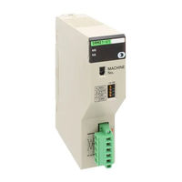
Omron CS1W-DRM21 Operation Manual (296 pages)
SYSMAC CS/CJ Series
Brand:
Omron
| Category:
Control Unit
| Size: 4.73 MB
Table of Contents
Table of Contents
7
About this Manual
9
Precautions
15
General Precautions
16
Intended Audience
16
Safety Precautions
16
Operating Environment Precautions
17
Application Precautions
18
Conformance to EC Directives
20
Applicable Directives
20
Concepts
20
Conformance to EC Directives
21
Section 1 Features and System Configuration
23
Features and System Configuration
23
Overview of Devicenet
24
Overall System Configuration
25
Applicable Units and Devicenet Functions
28
Masters
31
Types of Slave
31
Devicenet Unit Features
41
Devicenet Configurator
41
Specifications
48
Devicenet Unit
48
Comparison between CS1W-DRM21(-V1) and CJ1W-DRM21
54
Comparison with Previous Models
55
Outline of the Configurator
59
Models
59
Configurator Specifications
60
Basic Operating Procedures
62
Network Installation Procedure
62
Hardware Preparations for Communications
62
Creating Routing Tables
63
Procedures Prior to Starting Communications
64
List of Usage Methods by Purpose
68
Section 2 Nomenclature and Installation
71
Nomenclature and Installation
71
Nomenclature and Functions
72
Status Indicators: MS and NS
73
Seven-Segment Display
74
Switch Settings
75
Installing the Devicenet Unit
77
System Configuration Precautions
77
Mounting
78
Handling Precautions
79
External Dimensions
81
Section 3 Allocated Cio and DM Words
83
Allocated CIO and DM Words
83
Overview of Word Allocations
84
Allocated CIO Area Words
85
Allocated DM Area Words
85
Allocated CIO Area Words
86
Software Switches 1 (Word N)
86
Software Switches 2 (Word N+1)
91
Master COS Send Switches (Words N+2 to N+5)
94
Disconnect/Connect Switches (Words N+6 to N+9)
95
Unit Status 1 (Word N+10)
96
Unit Status 2 (Word N+11)
97
Master Status 1 (Word N+12)
99
Master Status 2 (Word N+13)
100
Slave Status 1 (Word N+14)
101
Slave Status 2 (Word N+15)
103
Registered Slave Table (Words N+16 to N+19)
103
Normal Slave Table (Words N+20 to N+23)
104
C200H Master Replacement Master Status 1 (Word N+24)
104
Allocated DM Area Words
106
Communications Cycle Time Setup Table
106
Master User Allocations Setup Table
107
Allocation Size Setup Table
109
Slave User Allocations Setup Table
110
Communications Cycle Time Reference Table
112
Master User-Set Allocations Reference Table
112
Slave User-Set Allocations Reference Table
113
Slave Detailed Status
114
Section 4 Remote I\/O Master Communications
117
Remote I/O Master Communications
117
Master Remote I/O Communications
118
Allocations
118
Remote I/O Master Specifications
121
Precautions on the Number of Master Units
122
Procedure for Using Remote I/O Master
123
Scan List
125
Fixed Allocations
127
Allocated Words
127
Procedure
128
Changing System Components
131
Fixed Allocations Example
131
User-Set Allocations
133
Starting and Stopping Remote I/O Communications
142
Example of Ladder Programming for Remote I/O Communications
142
Starting Remote I/O Communications
142
Stopping Remote I/O Communications
142
Restarting Remote I/O Communications
142
Errors that May Occur in Remote I/O Communications
144
Section 5 Remote I\/O Slave Communications
147
Remote I/O Slave Communications
147
Slave Remote I/O Communications
148
Allocation Methods
148
Remote I/O and Slave Communications Specifications
149
Procedures for Using Remote I/O Slave Communications
149
Fixed Allocations
151
Allocated Words
151
Procedure
151
User-Set Allocations
152
Connection Types
153
Procedure
153
Connection Types
156
Section 6 Message Communications
159
Message Communications
159
Overview
160
Outline of Message Communications
160
FINS Message Communications
161
Explicit Message Communications
163
Message Communications Specifications
164
Message Communications Error Indications
165
Message Monitoring Timer
166
Message Communications Errors
166
FINS Commands and Responses
167
FINS Communications
167
Sending/Receiving FINS Command/Responses
168
Units Supporting FINS Communications
169
FINS Command Lists
169
Using FINS Message Communications
171
Setting Node Addresses
171
Creating Routing Tables
171
Data Send/Receive Instructions
174
Sending FINS Commands
176
Using SEND(090), RECV(098), and CMND(490)
177
Connecting Networks for FINS Communications
182
Sending Explicit Messages
183
Sending Explicit Messages
184
Sending Explicit Messages Using CMND(490)
186
Receiving Explicit Messages
190
List of PLC Object Services
191
Section 7 Other Functions
203
Other Functions
203
Connecting to the CX-Programmer Via the Devicenet
204
Setting Node Addresses
205
Setting the Message Monitoring Timer of the Devicenet Unit
205
The Devicenet
207
Response When Using the CX-Programmer Via the Devicenet
207
Memory Card Backup Functions
208
Outline of Functions
209
File Names
210
Simple Backup Function
211
Overview of Function
211
Applications
211
Operating Methods
212
Section 8 Communications Timing
215
Communications Timing
215
Remote I/O Communications Characteristics
216
Communications Cycle Time and Refresh Time
216
I/O Response Time
219
More than One Master in Network
221
System Startup Time
221
Message Communications
222
Message Communications Time
222
Calculating the Maximum Message Response Time
223
Section 9 Troubleshooting and Maintenance
227
Troubleshooting and Maintenance
227
Troubleshooting with the Devicenet Unit Indicators
228
Determining Operating Status from the Indicators
228
Troubleshooting Errors Occurring in the Devicenet Unit
229
Error Log Functions
246
Error Log Table
246
Error Codes and Detail Codes
247
Troubleshooting
250
CPU Unit's ERR/ALM Indicator Lit or Flashing
250
Remote I/O Communications Disabled
250
I/O Link Problems
251
Communications Error Operation Settings
252
Scan List Problems
252
Maintenance and Replacement
253
Cleaning
253
Inspection
253
Replacing Faulty Units
254
Allocation Differences from C200H Devicenet Master Units
257
Devicenet Connections
263
FINS Commands and Responses for Devicenet Units
269
Multi-Vendor Applications
275
Devicenet Explicit Message Send Command for Other Manufacturer Nodes
285
Index
287
Revision History
291
Advertisement
Related Products
OMRON CS1W-SRM21 - 08-2007
OMRON CS1W-NC271 - 12-2009
OMRON CS1W-213 - REV 02-2008
OMRON CS1W-233 - REV 02-2008
OMRON CS1W-433 - REV 02-2008
OMRON CS1W-MC221 -
OMRON CS1W-MCH71 -
OMRON CS1W-NC271
Omron SYSMAC CS1W-NC213
Omron SYSMAC CS1W-NC233
Omron Categories
Blood Pressure Monitor
Controller
Accessories
Switch
Inverter
More Omron Manuals
Login
Sign In
OR
Sign in with Facebook
Sign in with Google
Upload manual
Upload from disk
Upload from URL