Sign In
Upload
Manuals
Brands
Nortel Manuals
Telephone System
BCM1000
Nortel BCM1000 Manuals
Manuals and User Guides for Nortel BCM1000. We have
2
Nortel BCM1000 manuals available for free PDF download: Installation And Maintenance Manual, Keycode Installation Manual
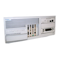
Nortel BCM1000 Installation And Maintenance Manual (311 pages)
Nortel Networks Business Communications Manager Installation and Maintenance Guide
Brand:
Nortel
| Category:
Telephone System
| Size: 5.64 MB
Table of Contents
Enhanced 911 Configuration
4
Radio-Frequency Interference
4
Hearing Aid Compatibility
5
Network Connection
5
Canada and US
5
Telecommunication Registration
5
Electromagnetic Compatibility
6
Repairs
6
Rights of the Telecommunications Company
6
Telephone Company Registration
6
Use of a Music Source
6
Canadian Regulations - Please Read Carefully
7
US Regulations - Please Read Carefully
8
Safety
12
Additional Safety Information
12
Limited Warranty
13
Exclusions
13
Warranty Repair Services
14
After Warranty Service
14
Table of Contents
15
North American Regulatory Information
29
Preface
29
Safety
29
Symbols Used in this Guide
30
Acronyms
31
Table 1 Interface Harmonized Standards
31
Text Conventions
31
Related Publications
33
Federal Communications Commission (FCC) Notice
34
System Documentation Map
34
EMI/EMC (FCC Part 15)
35
Installation Documentation
35
Important Safety Instructions
36
Operations Documentation
36
International Regulatory Information
37
Call Management Documentation
37
Unified Manager and Hardware Maintenance Documentation
38
Multi-Site Administration: Network Configuration Manager
38
How to Get Help
39
Chapter 1 Introducing the Business Communications Manager
41
Business Communications Manager System Components
41
Figure 1 Business Communications Manager Core System Components
41
Computer Components
42
Figure 2
42
Figure 2 External Functional Hardware, BCM1000
42
Hardware Components
42
Figure 3 BCM1000 Interior Components for Standard System (Pre-2.5)
43
Table 1 Basic BCM1000 Base Unit Specifications
43
Figure 4 BCM1000 Interior Components with a Standard Power Supply System (2.5)
44
Figure 5 BCM1000 Interior Components, Redundant System with Mirrored Hard Disks (2.5)
44
Telephony Components
46
Data Networking Components
48
Media Services Card
48
Figure 6 MSC Optional Equipment Ports
48
MSC IP Call Processing Hardware
49
Connection Ports
50
Figure 7 BCM1000 External Points of Connection
50
BCM1000 Leds
51
Figure 8 BCM1000 Operational Leds
51
System Options
52
Telephony Features and Options
52
Data Features
54
Business Communications Manager Expansion Unit
55
Figure 9 DS256 Connector on a BCM1000 and a Bcm1000E
56
Installation Process Overview
57
Figure 10 Installation and Initialization Overview
57
Data Networking
58
Components
58
Chapter 2 Telephony Hardware
59
Media Bay Module Common Features
60
Leds
60
Figure 11 Telephony Hardware Components
60
Figure 12 Module LED Locations
60
Table 2 Module Power and Status LED States
60
Power Connections
61
Figure 13 Rear of Modules Showing DS256 and Power Connectors
61
DIP Switches
62
Figure 14 DIP Switch Positions on the Modules
62
Trunk Media Bay Modules
63
Table 3 Trunk Media Bay Modules
63
Digital Trunk Media Bay Module
64
Figure 15 DTM Module Leds and Connectors, Front View
64
Table 4 DTM LED Functions
64
Figure 16 GATM4/GATM8 Module Faceplate
65
Global Analog Trunk Module (GATM)
65
Caller ID Trunk Media Bay Module
66
Basic Rate Interface Media Bay Module
67
Figure 17 CTM and CTM8 Leds and Jacks
67
Figure 18 BRI Leds and Jacks
67
Station Media Bay Modules
68
Table 5 Station Modules
68
Digital Station Media Bay Module
69
Figure 19 Faceplates of DSM 16/DSM 16+ and DSM 32/DSM32
69
4X16 Media Bay Module
70
Analog Station Modules and Analog Devices
70
Figure 20 Faceplate of 4X16 Module LEDS, Connectors, and Jacks
70
Table 6 Analog Engineering Specifications
70
Analog Station Media Bay Module
72
Figure 21 ASM 8 Front View
72
Global Analog Station Media Bay Module (GASM8)
73
Specialized Media Bay Modules
73
Table 7 Specialized Modules
73
Fiber Expansion Media Bay Module
74
Figure 22 FEM Leds
74
Digital Drop and Insert MUX (DDIM)
75
Figure 23 Digital Drop and Insert (DDIM) Faceplate Leds and Connectors
75
Telephones and Adapters
76
Cordless and Wireless Systems
79
Digital Mobility Solutions
79
Wireless LAN Telephony
79
Digital 7406 System Components
80
Chapter 3 Auxiliary Requirements
81
Computer Specifications
81
Security Changes
81
Browser Requirements
82
Preloading Java Class Files on Your Workstation
83
Optimizing Unified Manager Speed
83
Using an HTTP Proxy Server
83
Chapter 4 Selecting the Media Bay Modules for Your System
85
Figure 24 Process for Determining Modules
85
Selecting the Trunk Media Bay Modules
86
Table 8 Determining Trunk Module Requirements
86
Selecting the Station Media Bay Modules
87
Table 9 Station Media Bay Modules Required
87
Upgrading from an Existing Norstar System
88
Determining System Capacity
88
Understanding DS30 Bus Blocks
88
Changing the DS30 Split
89
Explaining Double Density
89
Figure 25 DS30 Bus Model
89
Setting Offsets
90
Figure 26 Offsets Are Part of DS30 Line/Dn Groups
91
Determining Module DS30 Bus Requirements
92
Figure 27 DS30 Bus Space Requirements for Media Bay Modules
92
Table 10 Matching Modules to DS30 Bus Capacity
93
Chapter 5 Installing the BCM1000
95
Preparation Checklist
95
Environment Checklist
95
Electrical Requirements
96
Internal Wiring Requirements
96
Digital Loop
96
Analog Loop
97
System Equipment and Supplies
97
Basic Hardware
97
Optional Equipment
97
Equipment for Installing the BCM1000
98
Installing the BCM1000 in a Rack
98
Attaching the Rack Mounting Brackets
98
Installing the BCM1000 into the Rack
99
Figure 28 Attaching the Rack Mounting Bracket to the BCM1000
99
Figure 29 Fasten the BCM1000 to the Equipment Rack
99
Installing the BCM1000 on the Wall
100
Figure 30 Attaching the Mounting Brackets to the BCM1000
101
Figure 31 Mount the BCM1000 on the Wall
102
Installing the BCM1000 on a Flat Surface
103
Replacing Your BCM1000 Hardware
103
Chapter 6 Installing the Bcm1000E (Expansion Unit)
105
Installing the Bcm1000E into a Rack
105
Attaching the Mounting Brackets
105
Figure 32 Attach the Rack Mounting Bracket to the Bcm1000E
105
Attaching the Bcm1000E to the Rack
106
Figure 33 Fasten the Bcm1000E to the Equipment Rack
106
Installing the Bcm1000E on the Wall
107
Figure 34 Attaching the Wall Mounting Bracket to the Bcm1000E
107
Installing the Bcm1000E on a Flat Surface
108
Connecting the Bcm1000E to the BCM1000
108
Figure 35 DS256 Connector on the Bcm1000E
108
Figure 36 BCM1000 DS258 Connector
109
Chapter 7 Setting Media Bay Module DIP Switches
111
Rules for Assigning DS30 Bus Blocks and Offsets
111
Notes about Assigning Modules
111
Choosing the Assigned Order for Modules
112
Figure 37 Assigning the Modules to the DS30 Bus Hierarchy
113
Figure 38 Assigning Double Density Modules to the DS30 Bus Hierarchy
114
Determining Module DIP Switch Settings
115
Figure 39 How to Use the Configuration Map
115
Table 11 Possible Media Bay Module DIP Switch Settings, Single Density
116
Table 12 Possible Media Bay Module DIP Switch Settings for Double Density
117
Setting the DIP Switches on the Modules
118
Figure 40 Switches on the Media Bay Module
118
Line and Extension Numbers for Specific Modules
119
DTM Switch Settings
119
Table 13 DTM Switch Settings (T1)
119
Table 14 DTM Switch Settings (North American PRI)
119
BRI Switch Settings
120
Table 15 DTM Switch Settings (E1 and UK PRI)
120
Table 16 BRIM S/T Switch Settings
120
CTM/GATM Switch Settings
121
GATM Switch Settings
122
Figure 41 Rear of GATM Module, Showing DIP Switch Locations
122
CTM/GATM DIP Switch Settings
123
Table 17 CTM/GATM4 and CTM8/GATM8 DS30 and Offset Switch Settings
123
Table 18 Global Analog Trunk Module DIP Switch Settings
124
4X16 Switch Settings
125
Table 19 4X16 Switch Settings
125
ASM 8/GASM8 Switch Settings
127
Table 20 ASM8 Settings for Upgraded 2.5 Systems and New 3.0 Systems
127
GASM8 Country Switch Settings
129
Table 21 GASM8 Dip Switch Modes
129
DSM Switch Settings
130
Table 22 GASM8 Country Select Dip Switch Settings
130
Table 23 DSM Single Density Settings for BCM 2.5 Systems Upgraded to BCM 3.0 or Newer Software
131
Table 24 DSM Single Density Switch Settings for New BCM 3.0 (or Newer) Systems
131
Table 25 DSM 16+ and DSM32+ Double Density Switch Settings for 2.5 Systems Upgraded to BCM 3.0 or Newer Software
132
Table 26 DSM 16+ and DSM32+ Double Density Switch Settings for New Systems with BCM
133
FEM Switch Settings
134
Table 27 FEM Switch Settings
134
Chapter 8 Installing Media Bay Modules
135
Figure 42 Process Map: Installing a Media Bay Module
135
Shutting down the System
136
Installing a Media Bay Module
137
Figure 43 Removing the Front Bezel
137
Figure 44 Identifying the Media Bay Module Latches
137
Figure 45 Warning of Possible Shorting Issue on Media Bay Modules
138
Reconnecting the Equipment
139
Replacing Media Bay Modules
140
Figure 46 Process Map: Replacing a Media Bay Module
140
Installation/Replacement Troubleshooting
141
Chapter 9 Starting the System
143
Checking Power and Wiring
144
Checking System Power and Status
145
Figure 47 Leds Confirm that BCM1000 Is Active
145
Table 28 BCM1000 LED States
145
Connecting the Data Networking Hardware
147
Connecting the Cards
147
Figure 48 Locating the Data Cards on the BCM1000
147
Connect Wiring to the WAN Card
148
Connecting Wiring to the LAN Card
148
Connect Wiring to the Modem Card
149
Table 29 DB25 Adapter Cable
149
Table 30 RS-422/EIA 530 Adapter Cable
150
Table 31 V.35 Adapter Cable
150
Replacing the Cards
151
Table 32 DB15 X.21 Adapter Cable
151
Setting Initial System Configurations
152
Required Data Parameters
152
Default IP Settings
152
Connecting When There Is an IP Address Conflict
153
Using a Null Modem Serial Cable
153
Figure 49 Serial Pinout
153
Table 33 Serial Port Pinout
153
Figure 50 Main Menu
155
Using an Ethernet Crossover Cable
156
Figure 51 Ethernet Crossover Cable
156
Entering the Software Keycodes
157
Regenerating Keys after System Replacement
157
Chapter 10 Wiring the Modules
159
Module Wiring Warnings
160
Figure 52 Process Map: Trunk and Station Wiring Process Map
160
Connecting Media Bay Modules to Service Providers
161
Figure 53 DTM RJ48C Wiring Array
161
Figure 54 CTM RJ11 Wiring Array
161
Figure 55 GATM Cable Wiring Diagram
162
Figure 56 BRI RJ45 Wiring Array
163
Wiring Media Bay Modules to Internal Connections
164
Figure 57 Wiring for DSM 16, 4X16, and DSM 32
165
Table 34 DSM Wiring Chart
165
Figure 58 Wiring for an ASM 8 or GASM8
166
Table 35 ASM Wiring Chart
166
FEM Wiring
167
Connecting the Fiber Cables
167
Table 36 Extension Comparison Chart
168
Chapter 11 Installing Telephones and Peripherals
169
System Telephones
169
Analog Terminal Adapter
169
Central Answering Position (Cap/Ecap)
170
Telephone Port and DN Cross-Reference
170
Table 37 Cross Referencing Ports and Dns on a 2.5 System Upgraded to 3.0 or Newer Software
171
Table 38 Cross Referencing Ports and Dns on a New Version 3.0 or Newer System
172
Installing an Emergency Telephone
173
Installing IP Telephones
173
Installing the Mobility Systems
173
Installing the 7406 Cordless Systems
174
Chapter 12 Installing Analog Terminal Adapters
175
Understanding Pre-Installation Requirements
175
Connecting an Analog Telephone
177
Figure 59 Analog Telephone Installation Overview
177
Connecting a Data Device
178
Figure 60 Data Communication Device Installation Overview
178
Connecting the ATA 2
179
Figure 61 ATA 2 Top View
179
Figure 62 ATA 2 Pin Outs
179
Mounting the ATA 2
180
Figure 63 ATA 2 Back View
180
Testing Insertion Loss Measurement
181
Figure 64 Insertion Loss from the CO to the Analog Telephone
181
Configuring the ATA 2
182
Chapter 13 Installing Optional Telephony Equipment
183
Auxiliary Ringer
183
Auxiliary Ringer Programming
183
Figure 65 Auxiliary Ringer Jack
183
External Paging System
184
Connecting the Paging System
184
Figure 66 Audio Input Jack
184
Contents
185
External Music Source
185
Music on Hold Specifications
185
Figure 67 Page Relay Jack
185
Connecting the External Music Source
186
External Music Source Programming
186
Figure 68 Music-On-Hold Jack
186
Chapter 14 Troubleshooting
187
Using the System Status Monitor to Monitor Leds
188
Figure 69 SSM Board Connections
188
Figure 70 LED Locations on the Face of the BCM1000
189
Figure 71 System Status Monitor LED Display Screen
189
Emergency Telephone Does Not Function
190
Figure 72 System Status Monitor LED Settings Record
190
Table 39 LED Display Screen Settings
190
ATA 2 Does Not Function
191
Checking the Wiring
191
Checking for Dial Tone at the ATA 2
192
Checking for Trunk Line Dial Tone to the ATA 2
192
Chapter 15 Preparing Hardware for Maintenance or Upgrades
193
Special Tools
193
Figure 73 Process Map: Preparing the Units for Maintenance
193
Shutting down the System Software
194
Shutting down the System Hardware
195
Removing the Top Cover from the Unit
195
Figure 74 Remove the Top Cover
195
Removing the Front Bezel
196
Restarting the System
196
Restoring the System to Operation
196
Figure 75 Removing the Front Bezel
196
Software Restart
197
Chapter 16 Replacing the Hard Disk
199
Figure 76 Process Map: Hard Disk Replacement
199
Removing the Hard Disk
200
Figure 77 Hard Disk Wiring (Single Disk) and Screw Locations (2.0 Hardware)
201
Figure 78 Hard Disk and Screw Locations (2.5 Version Hardware)
201
Figure 79 Remove the Brackets from the Hard Disk
202
Installing a New Hard Disk
203
Figure 80 Connect the Brackets to the Hard Disk (Single-Disk System)
203
Figure 81 Installing Two Hard Disks for a Mirrored Disk System
203
Figure 82 Cabling the RAID Board to the Hard Disks
204
Figures
204
Initializing the Hard Disk (Single-Disk System, BCM 2.5/2.5.1)
205
Figure 83 Main Menu Screen
205
Figure 84 Platform Initialization Menu Screen (BCM 2.5/2.5.1 Systems)
206
Figure 85 Profile Screen
207
Initializing the Hard Disk (Single-Disk System, BCM 3.0)
208
Figure 86 Platform Initialization Menu Screen
208
Figure 87 Platform Initialization Menu Screen
209
Figure 88 MSC Initialization Menu Screen
209
Initializing the Hard Disk (Single-Disk System BCM 3.0.1 and Newer Systems)
210
Figure 89 Main Menu Screen
211
Figure 90 Platform Initialization Menu Screen
211
Figure 91 Initialization Menu Screen
212
Figure 92 MSC Initialization Menu Screen
212
Figure 93 System Configuration Start Page
213
Figure 94 Quick Start Page
214
Installing the Mirrored Disk Controller
215
Figure 95 Base Unit with RAID Board, Plus Redundant Power and Fans
215
Figure 96 Clip the RAID Board Onto the Media Bay Module Housing
216
Installing the RAID Board
216
Connecting the RAID Board
217
Figure 97 RAID Board Leds on Face of Base Unit
217
Connecting RAID Board Ribbon Cables
218
Figure 98 RAID Board
218
Routing Power for Mirrored Systems
219
Power Routing for 2.5 Hardware
219
Figure 99 Connecting the Power Cables for Mirrored Disks, 2.5 Version of BCM1000
219
Power Routing for 2.0 Hardware
220
Figure 100 Connecting the Power Cables for Mirrored Disks, 2.0 Version of BCM1000
220
Figure 101 RAID Board Leds
221
RAID Board Leds
221
Table 40 RAID Board LED States
221
Controlling and Monitoring Mirroring Operations
222
Table 41 HDD Mirror Settings
222
Chapter 17 Adding or Replacing a Cooling Fan
223
Figure 102 Process Map: Replacing a Cooling Fan
223
Troubleshooting Fan Operation
224
Removing a Fan from the BCM1000
224
Figure 103 Business Communications Manager Operational Leds
224
Table 42 Fan and Temperature Leds on the Server
224
Figure 104 Remove the Fan Cable from Motherboard (Pre-2.5 Chassis)
225
Figure 105 Remove the Fan Cables from SSM Board (2.5 Models)
225
Figure 106 Removing the Fan (BCM1000 Version 2.5 Single-Fan Model)
226
Figure 107 Screw Attachments Beside Fan Holes (BCM1000 Version 2.5 Redundant Model)
226
Figure 108 Installing Piggy-Backed Fans
227
Replacing the Cooling Fan
227
Removing a Fan from the Bcm1000E
228
Figure 109 Connect the Redundant Fan Cable to the Adapter
228
Figure 110 Fan Screws Location in Bcm1000E, 2.0 Models
229
Figure 111 Fan Screws Location in Bcm1000E, 2.5 Redundancy Models
229
Replacing a Fan into the Bcm1000E
230
Chapter 18 Replacing a Power Supply
231
Replacing a Standard Power Supply
231
Figure 112 Process Map: Replacing a Standard Power Supply
231
Figure 113 Removing Power Supply Bracket (Single-Power Supply Models)
232
Removing the Standard Power Supply
232
Figure 114 Remove the Power Supply Screws
233
Installing a Standard Power Supply
233
Upgrading to a Redundant Power Supply
234
Figure 115 Process Map: Upgrading to a Redundant Power Supply
234
Table 43 Power Supply LED
234
Figure 116 System Status Monitor Internal Connectors
235
Setting up the Base Unit
235
Figure 117 Remove the Knockout
236
Installing the Redundant Power Supply
236
Figure 118 Attach the Redundant Power Supply Housing
237
Figure 119 Securing the Power Supply Bracket
237
Figure 120 Insert and Attach the Modules
238
Replacing a Redundant Power Supply Module
239
Figure 121 Removing the Power Module
239
Replacing a Power Supply in an Bcm1000E
240
Figure 122 Bcm1000E, Standard Power Supply Interior Connections
240
Figure 123 Bcm1000E, Redundant Power Supply Interior Connections
241
Figure 124 Installing the Power Module in a Redundant Bcm1000E
241
Chapter 19 Replacing Data Cards and Processing Hardware
243
Replacing Data Cards
243
Figure 125 Process Map: Data Card Replacement
243
Figure 126 BCM1000 LAN Card Leds
244
Removing a Data Card
244
Table 44 BCM1000 PCI LED States
244
Figure 127 Install the LAN Card
245
Installing the Card
245
Replacing Pecs
246
Figure 128 Process Map: PEC Replacement
246
Figure 129 Removing or Replacing a PEC
247
Removing Pecs
247
Installing a PEC
248
Replacing Memory
249
Figure 130 Process Map: Memory Replacement
249
Figure 131 Removing and Replacing the Dimms
250
Replacing Memory DIMM Chips
250
Replacing the Clock/Calendar Battery
251
Figure 132 Process Map: Battery Replacement Overview
251
Figure 133 Removing the Clock/Calendar Battery
252
Removing the Clock/Calendar Battery
252
Installing the New Battery
253
Chapter 20 Moving and Replacing Telephones
255
Determining the Status of a Telephone
255
Moving Telephones
256
Replacing Telephones with Different Models
257
Status of the Replaced Telephone
257
Defining Region-Based Defaults
259
Region-Based System Settings
259
Core Software and Regions
260
Languages
260
Table 45 Core Software, Defined by Region and Carrier Profile
260
Table 46 Languages
260
Caller ID Displays
261
Table 47 South/Central America Language Breakout
261
Companding Law by Region
262
Mobility Services by Region
262
Table 48 Companding Law
262
Table 49 Mobility Services, by Region
262
Media Bay Module Availability by Region
263
Table 50 Module Availability, by Profile
263
FEM-Trunk Module Combinations by Region
264
Table 51 Trunk Availability, by Region
264
PRI Line Protocol Support, by Region
265
Table 52 PRI Line Protocol Supported, by Region
265
Supported ISDN Line Services
266
Table 53 ISDN Line Services
266
Table 54 ISDN Services, by Protocol
266
Defining Time Zones by Country and Language
267
System Feature Defaults
267
Table 55 Time/Date Formats Based on Language
267
Table 56 Region Defaults
267
Dialing Plan Defaults
270
Table 57 Default Dialing Restrictions, by Profile
270
BRI and PRI Line Types
271
Table 58 BRI and PRI Line Types (DTM and BRI Modules)
271
Callpilot Regions
272
Table 59 Callpilot Region Default Languages by Country
272
Table 60 Callpilot Feature Default Anomalies
273
Media Bay Module Combinations
275
Combining Ctms/Gatms and 4X16S
275
Table 61 Ctms/Gatms Combined with 4X16 Modules
275
Fully-Loaded Setup
276
Table 62 DSM Combined with 2 Dtms and 2 Asms
276
Table 63 Fully Loaded System Using Modules Set to Double Density
277
Changing Configurations
278
System Setup
278
Set Dns and Port Numbers
279
Table 64 Cross Referencing Ports and Dns
279
Glossary
281
Contents
283
Index
297
Advertisement
Nortel BCM1000 Keycode Installation Manual (16 pages)
Business Communications Manager
Brand:
Nortel
| Category:
Telephone System
| Size: 0.31 MB
Advertisement
Related Products
Nortel BM450
Nortel BMC II AMAT
Nortel BCM 450
Nortel BCM50
Nortel BCM200
Nortel BCM400
Nortel Business Communications Manager (BCM) & Norstar
Nortel BCM50 2.0
Nortel BCM 450 1.0
Nortel BCM 3.7
Nortel Categories
IP Phone
Telephone
Switch
Software
Server
More Nortel Manuals
Login
Sign In
OR
Sign in with Facebook
Sign in with Google
Upload manual
Upload from disk
Upload from URL