
Related Manuals for EverFocus ENVR8304D-8CH


Summary of Contents for EverFocus ENVR8304D-8CH
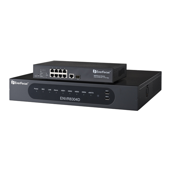
- Page 1 ENVR8304D-8CH 8-Channel Plug & Play NVR User’s Manual Copyright © EverFocus Electronics Corp, Release Date: July, 2013 Notice: This content is subject to be changed without notice.
- Page 2 All rights reserved. No part of the contents of this manual may be reproduced or transmitted in any form or by any means without written permission of the EverFocus Electronics Corporation. Release Date: July, 2013 QuickTime is a registered trademark of the Apple Computer, Inc.
-
Page 3: Safety Precautions
Safety Precautions Refer all work related to the installation of this product to qualified service personnel or system installers. Do not block the ventilation openings or slots on the cover. Do not drop metallic parts through slots. This could permanently damage the appliance. Turn the power off immediately and contact qualified service personnel for service. - Page 4 Follow Instructions All operating and use instructions should be followed. Cleaning Unplug the unit from the outlet before cleaning. Do not use liquid cleaners, abrasive or aerosol cleaners. Use a damp cloth for cleaning Attachments Do not use attachments not recommended by the product manufacturer as they may cause hazards.
- Page 5 This Product is RoHS compliant. Your EverFocus product is designed and manufactured with high quality materials and WEEE components which can be recycled and reused. This symbol means that electrical and electronic equipment, at their end-of-life, should be disposed of separately from your household waste.
-
Page 6: Table Of Contents
TABLE OF CONTENTS Introduction ........................1 1.1 Overview ........................2 1.2 Features ........................3 1.3 Packing List .........................4 1.4 Optional Accessories ....................5 1.5 Front Panel .........................6 1.6 Rear Panel ........................7 Installation .........................8 2.1 Hard Disk Drive Installation ..................8 2.1.1 Hard Disk Compatibility List ................10 2.2 Rack Mount ......................10 2.3 Basic Connection ......................11 2.3.1 Camera Connection ..................12... - Page 7 4.3 Channel Switching ....................38 4.4 Display ........................39 4.5 Sequence ........................40 4.6 Zoom ........................40 4.7 Archiving the Recordings or Log Data to the USB ............42 4.8 Logout ........................43 Search and Playback ......................44 5.1 Quick Playback ......................44 5.2 Playback Bar ......................45 5.3 Searching the Recordings for Playing Back ..............47 5.3.1 Time Search....................47 5.3.2 Event Search ....................48 5.3.3 Snapshot Search .....................49...
- Page 8 6.5.1 Monitor OSD ....................87 6.5.2 M/T SEQ ......................88 6.6 Network........................89 6.6.1 LAN & WAN ....................89 6.6.2 Email ......................92 6.6.3 DDNS ......................93 6.6.3.1 EverFocus DDNS ................94 6.6.3.2 www.dyndns.org ................95 6.6.4 FTP .........................96 6.6.5 Alarm Server ....................97 6.6.6 Network Test ....................98 6.7 Schedule ........................99 6.7.1 Express Setup ....................99...
- Page 9 7.5.2.2 PTZ ....................132 7.5.3 Video Adjust ....................139 7.6 PTZ ......................... 141 Specifications ......................... 143 Appendix A: Network Overview ..................... 147 Appendix B: Linksys & D-Link Port Forwarding ............... 151 Appendix C: IR Remote Control ....................155 viii...
-
Page 10: Introduction
Featuring a standalone network video recorder up to 8 channels, along with a series of NVR EverFocus megapixel cameras, the NVR Solution offers a complete system kit that can be easily installed in a matter of minutes. There is no need to purchase extra computers or software to operate the system. -
Page 11: Overview
ENVR8304D-8CH 1.1 Overview Front View IR Remote Control Mouse USB Memory Stick Rear View PowerVideo Plus Web Remote Client (CMS) Line Level EKB200 eSATA HDD RS-485 Audio In Keyborad Expansion Device Network (EDA450) RS-232 Data Input Power Cord Line Level... -
Page 12: Features
• RAID5 – for full data protection • Free EverFocus DDNS Service – static IP address is not required for reliable remote access • Supports one eSATA port for external HDD (optional:EDA450) • Supports live monitoring and playback of video from mobile devices via MobileFocus / MobileFocus Plus Apps •... -
Page 13: Packing List
Note: 1. Equipment configurations and supplied accessories vary by country. Please consult your local EverFocus office or agents for more information. Please also keep the shipping carton for possible future use. 2. Contact the shipper if any items appear to have been damaged in the shipping process. -
Page 14: Optional Accessories
EKB500 (RS-485 keyboard: connect to the RS-485 port to control the PTZ cameras connected to the NVR). Please refer to 6.1 Camera and the User Manual of the EKB500 Keyboard. • EDA450 (eSATA Storage Device: connect to the eSATA port of the ENVR8304D-8CH). Please refer to No. 2, Figure 1-3. -
Page 15: Front Panel
ENVR8304D-8CH 1.5 Front Panel Figure 1-2 No. Name Description Power Indicates the power is on. Indicates the NVR is recording. Indicates the NVR is connected to the network. Alarm Indicates an alarm input is triggered. HDD1~4 Separately indicates the internal HDD 1~4 is activating. -
Page 16: Rear Panel
Cord. RS-232 Port Connects to the RS-232 device. Please refer to 2.3.7 RS-232 Port. Connects to the RS-485 device, such as EverFocus’ EKB-500 RS-485 Port keyboard. Please refer to 2.3.6 RS-485 Port. Connects to the Main monitor using a HDMI cable. Please refer to HDMI Port 2.3.3 Monitor Connection. -
Page 17: Installation
ENVR8304D-8CH Chapter Installation 2.1 Hard Disk Drive Installation 1. Make sure the NVR is power-off. 2. Unscrew the ten housing screws on the NVR, and open the housing. Figure 2-1 3. Screw two HDD brackets on both sides of the HDDs using the Sliver Screws. - Page 18 ENVR8304D-8CH 5. Connect the internal power cable to the HDD. Figure 2-4 Note: The internal power cable is connected to the Main board inside the NVR. The power cable features two connectors, which can be used to connect to two HDDs.
-
Page 19: Hard Disk Compatibility List
ENVR8304D-8CH 2.1.1 Hard Disk Compatibility List Please use the hard disk models recommended in the list below to ensure your hard disks will be compatible. SATA Hard Disk Model Capacity SV35.5 SATA2 / ST3500410SV 500GB SV35.5 SATA2 / ST31000525SV SV35.5 SATA3 / ST3500411SV... -
Page 20: Basic Connection
ENVR8304D-8CH 2.3 Basic Connection The instructions below describe the basic connection for ENVR8304D-8CH Web Remote PowerVideo Plus Client (CMS) Line Level Main Monitor Main Monitor Audio In (HDMI) (VGA) Network EVNR8304D-8CH NVR Smart Switch Power Supply Line Level Mouse &... -
Page 21: Camera Connection
ENVR8304D-8CH 2.3.1 Camera Connection Connect the LAN Port of the NVR to the Port 9 of EverFocus’ NVR Smart Switch using a RJ45 CAT5 10/100Mb Ethernet cable. Connect the IP cameras to the 1~8 camera ports at the rear of the PoE switch using Ethernet cables. -
Page 22: Cable Length Extension
ENVR8304D-8CH 2.3.2 Cable Length Extension The Ethernet connection is effective within 100 meters in distance. If the distance between the PoE switch and the IP cameras is over 100 meters, you need to use a hub, PoE injector or PoE extender, which should be connected to one camera only. -
Page 23: Monitor Connection
ENVR8304D-8CH 2.3.3 Monitor Connection The NVR provides 2 main monitor outputs with identical functionality - VGA and HDMI. You can connect the monitor to the VGA or HDMI port on the rear panel of the NVR. Both of the VGA and HDMI video outputs can be used simultaneously and deliver full HD resolution (1920 x 1080, progressive, 60 Hz. -
Page 24: Display Aspect Ratio
ENVR8304D-8CH 2.3.4 Display Aspect Ratio It is recommended to select the same ratio of the screen resolution and the camera live view display to avoid black bars showing on the live view screen as the images below. If you select 1920x1080 (16:9) screen resolution in the Screen Mode drop-down list (see 6.5.1 Monitor OSD), it is recommended to also change the camera live view display to 16:9 aspect ratio in the Ratio drop-down list (see 6.1.6 Adjust). -
Page 25: Alarm I/O
ENVR8304D-8CH 2.3.5 Alarm I/O The NVR provides two alarm inputs and two alarm outputs. Please refer to the table below for PIN assignment. Alarm In Alarm Out Figure 2-13 Alarm Input Description No. Description ALM_IN1 ALM_IN2 Alarm Input Contacts This NVR provides one alarm input per camera. All inputs are programmable N.O. (Normal Open) or N.C. -
Page 26: Port
The RS-485 port, located on the rear panel of the NVR, can be used to connect to an RS-485 keyboard, such as EverFocus’ EKB500, for controlling NVR and HD PTZ cameras. For details on the RS-485 configurations on the NVR, please refer to 6.8.5 I/O Control. The RS-485 pin... -
Page 27: Connecting The Nvr To The Network
ENVR8304D-8CH 2.5 Connecting the NVR to the Network There are three methods to connect the NVR to the network: Router or LAN Connection, Direct High‐Speed Connection and One‐to‐One Connection. For more information of the network, please refer to Appendix A. Network Overview. - Page 28 Once you have a straight through cable, plug one end into the LAN port on the back of the recorder and the other into the router. Log into the EverFocus NVR menu and go to the Network Setting Menu. To let the router automatically assign an address: ...
- Page 29 ENVR8304D-8CH Take the values for Subnet Mask and Default Gateway and input them into the NVR; these values should be exactly the same in both devices. However, you should change the last number of the IP address. For example, if the IP address of the computer is 192.168.2.101, the NVR’s IP address should be 192.168.2.50.
-
Page 30: Direct High-Speed Connection
Once you have a straight through cable plug one end into the LAN port on the back of the recorder and the other into the high speed modem. Log into the EverFocus NVR menu and go to the Network Setting Menu. Input the Static IP address, the Subnet Mask, and the Gateway that you obtained ... -
Page 31: One-To-One Connection
NVR and the other into the network card on the back of the computer. Log into the EverFocus NVR menu and go to the Network Setting Menu. You must use the Static IP option for this type of connection. - Page 32 ENVR8304D-8CH Go to Start. Double-click on Control Panel. Figure 2-20 Click Network and Internet Connection. Figure 2-21 Click Network Connections. Figure 2-22...
- Page 33 ENVR8304D-8CH Right-click on Local Area Connection and select Properties. Figure 2-23 Click on Internet Protocol (TCP/IP) and then click Properties. Figure 2-24 Select Use the following IP address. Assign an IP address of 192.168.1.2, a Subnet Mask of 255.255.255.0, and a Default Gateway of 192.168.1.1 and then click OK.
- Page 34 ENVR8304D-8CH To access the NVR from the computer, simply open Internet Explorer and in the address bar type: http://192.168.1.3 Figure 2-25 Select Use the following IP address. Assign an IP address of 192.168.1.2, a Subnet Mask of 255.255.255.0, and a Default Gateway of 192.168.1.1 and then click OK.
-
Page 35: Checking The Dynamic Ip Address
You can look up the IP address and access the Web interface of the NVR using the IP Utility (IPU) program, which is contained in the CD. It can also be downloaded from EverFocus’ Website: http://www.everfocus.com/tools.cfm. Please connect the NVR in the same LAN of your computer. - Page 36 ENVR8304D-8CH 4. Type the user ID and password. Click OK. Note: 1. The default user ID is admin and the default password is 11111111. 2. If you select more than one NVRs that have the same user ID / password, you will be able to log in several NVRs at once.
- Page 37 9. When first connecting to the NVR’s IP address, the following dialog may appear. Please check the “Always trust content from this publisher” box and click the Run button to run the EverFocus Viewer application. Figure 2-30 10. You may need to turn User Account Control off if you still can’t see the Remote Live View.
-
Page 38: General Operation
Chapter 3. General Operation There are three ways to control the ENVR8304D-8CH: with a Mouse, the handheld IR Remote Controller, or the optional device EKB500 Keyboard. For details on the IR remote control, please refer to Appendix C, IR Remote Control. This chapter will discuss the basic operations using the mouse and the front panel buttons. -
Page 39: Opening Osd Root Menu
ENVR8304D-8CH The default user name and password are: User: admin Password: 11111111 Note: For details on setting up multiple user accounts, please refer to 6.8.4 User Management. Click Login to log in the NVR. 3.2 Opening OSD Root Menu Right-click the mouse, the OSD Root Menu appears. -
Page 40: Camera Selection
ENVR8304D-8CH On-Screen Keyboard: Click on a button to input that character. The buttons on the right and bottom have the following functions: Caps Switch to capital letters Delete the letter backwards ← Confirm the selection Move to left Move to right... -
Page 41: Enabling Audio
ENVR8304D-8CH 3.5 Enabling Audio In order to utilize the audio output function, you need to enable the Record Audio function. Please follow the instructions below before switching on the audio function. Note: The Audio function is unavailable for Germany. 1. Connect the audio source and/or audio output amplifier to the NVR. -
Page 42: Osd Root Menu
ENVR8304D-8CH Chapter 4. OSD Root Menu Figure 4-1 Name Description Click to display the Playback Bar for viewing the recording videos. For Playback details, please refer to 5. Search and Playback. Click to display the PTZ Control Panel for controlling the connected PTZ cameras. - Page 43 ENVR8304D-8CH Click to display the Channel Changing Bar as show below. To switch the selected camera to a specific channel, please refer to 4.3 Channel Switching. Channel Click to display system information icons or status icons on the live view Display screen.
-
Page 44: Ptz
ENVR8304D-8CH 4.1 PTZ You can use the PTZ Control Panel to control the connected PTZ cameras. To bring up the PTZ control panel, on the OSD Root Menu, click the PTZ button The following actions can be performed using the PTZ Control Panel: 1. - Page 45 9. To operate the Auto Pan function, click the Auto Pan button. 10. To operate the Pattern function, click the Pattern button. The Pattern is the “0” Tour in EverFocus and Pelco PTZ cameras. 11. To operate the Tour function: a.
-
Page 46: Express Control Of Ptz
ENVR8304D-8CH 4.1.1 Express Control of PTZ If the PTZ Control Panel has first been opened and then hidden, the mouse can be used to control basic PTZ functions. Move your mouse cursor on the screen, the mouse cursor will turn into a control icon (direction, focus or zoom) in different areas of the screen. You can control PTZ direction, focus and zoom by clicking directly on the screen. -
Page 47: Layout Switching
ENVR8304D-8CH 4.2 Layout Switching The NVR have 4 screen division types available. The seven layouts are shown as below: Figure 4-4 To change layout, follow the steps below: By mouse: Right-click to bring up the OSD Root Menu and click the Layout icon. Click on the desired layout. -
Page 48: Display
ENVR8304D-8CH 4.4 Display You can display system and camera status on the live view screen. Follow the steps below: 1. Click the Display button on the OSD Root Menu or press the Display button on the front panel to display the system and camera status. Click the button to choose the desired display mode: 2. -
Page 49: Sequence
ENVR8304D-8CH 4.5 Sequence The sequence function is used to display each channel in sequence mode. To enable this function: By Mouse: Click the Sequence button to enter the sequential switching mode. The NVR will display one channel at a time in full screen. The channels will be displayed in the sequence and for the amount of time as configured in the System >... - Page 50 ENVR8304D-8CH To enter the Zoom mode: Select a camera and then click the Zoom button on the OSD Root Menu to zoom in the camera view to 2X. The ZOOM 2X stamp will be displayed on the top screen. Navigate the camera view to the desired position by moving your mouse cursor over the camera view.
-
Page 51: Archiving The Recordings Or Log Data To The Usb
ENVR8304D-8CH 4.7 Archiving the Recordings or Log Data to the USB You can archive the recordings or log data (event and motion) to the USB storage device. On the OSD Root Menu, click the Copy icon , the following menu appears. -
Page 52: Logout
ENVR8304D-8CH 4.8 Logout You can log out the NVR by clicking the Logout icon on the OSD Root Menu to bring up the Logout Confirmation window as Figure 4-9. Press “Yes” when you are ready to logout of the system. You will need to login again before accessing the OSD Root Menu. -
Page 53: Search And Playback
ENVR8304D-8CH Chapter 5. Search and Playback You can use the Quick Playback function to play back the recordings start from the pre-configured time or use the Search functions to search for the desired recordings for playing back. 5.1 Quick Playback To start using the Quick Playback function, follow the steps below: 1. -
Page 54: Playback Bar
ENVR8304D-8CH 5.2 Playback Bar The playback bar is the fastest way to show video from the exact time which users want to see. The playback bar allows users to see both a timeline and the current playback indicator. Users can then click the timeline to move the indicator to the desired position. - Page 55 ENVR8304D-8CH No. Name Description Click to play the recorded data forward. Click this button again Play/Pause to Pause the playback. Click the Stop button to stop all playback actions and exit the playback area. Fast Forward Click to play the recorded data in fast forward.
-
Page 56: Searching The Recordings For Playing Back
ENVR8304D-8CH 5.3 Searching the Recordings for Playing Back You can search the recordings for playing back by using the Search menu. On the left side of the Search menu, select Time Search, Event Search, Smart Search, Snapshot Search or POS search to enter to the setup menu. -
Page 57: Event Search
ENVR8304D-8CH 5.3.2 Event Search Figure 5-5 Start Date / End Date: Click to bring up the on-screen keyboard to select the start / end date. Start Time / End Time: Click to bring up the on-screen clock to select the start / end time. -
Page 58: Snapshot Search
ENVR8304D-8CH 5.3.3 Snapshot Search You can display video frames in snapshot and resume a video from where the snapshot has been set up. Figure 5-9 Search Date: Click to bring up the on-screen keyboard to select the date. Search Time: Click to bring up the on-screen clock to select time. - Page 59 ENVR8304D-8CH To resume the video: 1. Click the Search button, the search results are displayed in 16 screen division. In this picture, you can see the time layouts on the upper-left corner of each snapshot, which are set up with 5-minute interval.
-
Page 60: Pos Search
ENVR8304D-8CH 5.3.4 POS Search The POS Search function allows users to search and play back the recordings with the POS transaction data within a specific time. Figure 5-12 Start Date / End Date: Click to bring up the on-screen keyboard to select the start / end date. - Page 61 ENVR8304D-8CH You need to set up the POS settings before searching the video with POS transaction data. Please follow the steps below: Connect the POS system to the RS-232 port at the rear panel of the NVR. Make sure the RS-232 settings of the NVR are the same as those of the POS system.
-
Page 62: Configuration
Chapter 6. Configuration The ENVR8304D-8CH can be configured through a series of menus on screen by using a Mouse, the supplied IR Remote Control, or the optional device EKB500 keyboard. The following operations are examples of using a Mouse. This chapter describes the functions and options of the Configuration Setting in the on-screen display (OSD) menus. - Page 63 ENVR8304D-8CH List of Configuration Options: Please find the topic of interest by referring to the section prefixed to each option. 6.1.1 Camera Status 6.1.2 Basic 6.1.3 PTZ 6.1 Camera 6.1.4 Tracking 6.1.5 Pattern Tour 6.1.6 Adjust 6.2.1 Record 6.2 Record & Playback 6.2.2 Quick Archive...
-
Page 64: Camera
ENVR8304D-8CH 6.1 Camera If the NVR doesn’t detect any IP cameras, the Basic, PTZ, Tracking, Pattern Tour and Adjust setting pages cannot be used. Therefore, make sure the IP cameras are properly connected to the NVR via the Smart Switch. -
Page 65: Basic
ENVR8304D-8CH 6.1.2 Basic Figure 6-4 Channel Number: Select a desired channel for configuration. Device Title: Enter a camera title. Record Dual Stream: Select to enable or disable the dual streams recording function. Record Mode: Select a recording mode from the drop-down list. - Page 66 ENVR8304D-8CH Event Speed: S elect a frame rate per second (FPS) for continuous recording. The frame rate is limited by the maximum total recording capacity of the NVR as allocated across all the installed cameras. Apply To: Click to apply the same settings to the desired cameras.
-
Page 67: Ptz
ENVR8304D-8CH 6.1.3 You can set up the Preset and Auto Pan settings in this page. Figure 6-4 【 Camera 】 : Select a PTZ camera. 【 Speed 】 : Select a pan and tilt speed from the Speed drop-down list for the camera to move to the directions when you use the direction buttons during the configuration period 【... - Page 68 ENVR8304D-8CH Preset: You can configure up to 192 preset positions in this field. Figure 6-6 To set up a Preset Positions: 1. Adjust the camera view to a desired position using the direction button. You can select the pan / tilt speed from the Speed drop-down list for controlling the direction buttons. Adjust zoom, focus and Iris if necessary.
- Page 69 ENVR8304D-8CH Auto Pan: You can only configure one Auto Pan sequence. The configured Auto Pan (A to B Pan) sequence will always be numbered as “1”. The number “2” will always be an endless pan around the given (not preconfigured) X/Y tilt axis.
-
Page 70: Tracking
ENVR8304D-8CH 6.1.4 Tracking Figure 6-8 To set up the Auto Tracking function: Auto Tracking Start Point: Check the box to enable a camera position to which the camera will return to after a tracking operation. Use the direction buttons to adjust the camera view to a desired position where you want to set up the position as the Auto Tracking Start Point. - Page 71 ENVR8304D-8CH Note: Please note that if enabling the Pan/Tilt Limits function, the position of the Start Point should be within the range of the Pan/Tilt Limits, or there will be a pop-up message showing “Setting error: Start Point is not inside Pan/Tilt Limits”.
-
Page 72: Pattern Tour
ENVR8304D-8CH 6.1.5 Pattern Tour Figure 6-9 Pattern: You are given 90 seconds to move the camera (via the PTZ buttons) to different positions (and different zoom / focus / Iris positions). The camera then saves that sequence under the Pattern No. you’ve selected. Up to 4 Patterns can be configured. - Page 73 ENVR8304D-8CH Tour: You can combine up to 16 preconfigured camera positions and patterns into one long sequence. Up to 16 Tour sequences can be set up. To set up a Pattern Sequence: 1. Select a number from the Tour No drop-down list.
-
Page 74: Adjust
ENVR8304D-8CH 6.1.6 Adjust Figure 6-11 Camera: Select a desired camera for adjusting the following settings. Ratio: Select 4:3 or 16:9 display aspect ratio of a camera, and its video will be displayed in 4:3 or 16:9 format on that channel screen. Please refer to 2.3.4 Display Aspect Ratio for more details. -
Page 75: Record & Playback
ENVR8304D-8CH 6.2 Record & Playback You can configure the basic recording settings on the hard disk. You can also configure the settings for Quick Archive and Quick Playback. 6.2.1 Record Figure 6-12 Record Overwrite: Check the box to overwrite the hard disk when it is full. Note that unless this box is checked, or the NVR will stop recording when the hard disk is full. -
Page 76: Quick Archive
ENVR8304D-8CH 6.2.2 Quick Archive Figure 6-13 You can quickly archive all the recordings to the USB storage device 1. Plug an USB storage device before quick archiving. 2. Click the Quick Archive Interval drop-down list and select an interval time (1, 5, 10, 15, 20, 30 or 60 minutes). -
Page 77: Playback
ENVR8304D-8CH 6.2.3 Playback Figure 6-14 Quick Playback: Check the box to enable the configured playback start time in the below field. Playback from X seconds ago: Set up a time between 60 and 3600 seconds for the playback start time. When you click the Playback button on the DSD Root menu, the system will play back the recordings start from the setup time. -
Page 78: Event
Network Alarm: Check the box to send out a network alarm to a client PC when an alarm event occurs. This feature works with EverFocus’ CMS software. You will need to configure the Alarm Server for the NVR to send network alarms to the client PC (see 6.6.5 Alarm... - Page 79 ENVR8304D-8CH Auto Lock: Check the box and the events will be recorded in a write protected segment of the hard disk (will not be overwritten). The NVR will lock a period of time when the alarm occurs. The length of the time depends on NVR setting (see 6.4.2 Lock / Format).
-
Page 80: Connection Loss
Network Alarm: Check the box to send out a network alarm to a client PC when video loss event occurs. This feature works with EverFocus’ CMS software. You will need to configure the Alarm Server for the NVR to send network alarms to the client PC (see 6.6.5 Alarm Server). - Page 81 ENVR8304D-8CH Output Type: Select an output type when an alarm is triggered. Timeout: Select this option and then set up the Timeout Duration in the field below, the alarm output will last for the setup duration time (10 ~ 150 seconds).
-
Page 82: Motion
Network Alarm: Check the box to send out a network alarm to a client PC when motion occurs. This feature works with EverFocus’ CMS software. You will need to configure the Alarm Server for the NVR to send network alarms to the client PC (see 6.6.5 Alarm Server). - Page 83 ENVR8304D-8CH FTP Upload: Check the box to enable uploading recordings to the FTP server function. To setup the FTP server, please refer to 6.6.4 FTP. FTP Upload File Type: Select MP4 file type to upload videos to FTP server; select JPEG file type to upload snapshots to the FTP server.
- Page 84 ENVR8304D-8CH To Edit the Motion Grids: 1. Click the Edit Motion Grid button, the Motion Setting menu appears. Figure 6-18 2. Click on the image and the grid will be displayed. 3. To set up a motion area, drag a rectangle with your mouse (from top to bottom / upper- left to lower-right).
-
Page 85: Other
Network Alarm: Check the box to send out a network alarm to a client PC when an alarm event occurs. This feature works with EverFocus’ CMS software. You will need to configure the Alarm Server for the NVR to send network alarms to the client PC (see 6.6.5 Alarm Server). -
Page 86: Disk Temperature
Network Alarm: Check the box to send out a network alarm to a client PC. This feature works with EverFocus’ CMS software. You will need to configure the Alarm Server for the NVR to send network alarms to the client PC (see 6.6.5 Alarm Server). -
Page 87: Disk Failure
Network Alarm: Check the box to send out a network alarm to a client PC when HD fails. This feature works with EverFocus’ CMS software. You will need to configure the Alarm Server for the NVR to send network alarms to the client PC (see 6.6.5 Alarm Server). -
Page 88: Disk Full
Network Alarm: Check the box to send out a network alarm to a client PC when HD is full. This feature works with EverFocus’ CMS software, including PowerCom and PowerVideo Plus. You will need to configure the Alarm Server for the NVR to send network alarms to the client PC (see 6.6.5 Alarm Server). -
Page 89: Disk Off
Network Alarm: Check the box to send out a network alarm to a client PC when HD is off. This feature works with EverFocus’ CMS software. You will need to configure the Alarm Server for the NVR to send network alarms to the client PC (see 6.6.5 Alarm Server). -
Page 90: Power Loss
Network Alarm: Check the box to send out a network alarm to a client PC when power has been restored. This feature works with EverFocus’ CMS software. You will need to configure the Alarm Server for the NVR to send network alarms to the client PC (see 6.6.5 Alarm Server). -
Page 91: Network Loss
ENVR8304D-8CH 6.3.4.7 Network Loss Figure 6-25 Log: Check the box to record alarm events to log data. Buzzer: Check the box to enable buzzer when network is lost. Alarm Output: Select an alarm output number. When an alarm is triggered, the signal will be transmitted through the selected alarm output relay. -
Page 92: Disk
ENVR8304D-8CH 6.4 Disk The Disk menu is used to review the NVR’s hard drive settings and status. No value in this menu can be configured by the operator. 6.4.1 Disk Figure 6-26 Record Time (Start): Shows the earliest recording time of the NVR. -
Page 93: Lock / Format
ENVR8304D-8CH 6.4.2 Lock / Format Figure 6-27 Maximum Lock (%): Sets the maximum percentage of the hard disk space reserved for Locked Event Recordings. To set up the Locked Event Recordings, please select the Auto Lock item in 6.4.3 Motion or 6.4.1 Alarm. -
Page 94: Raid
ENVR8304D-8CH 6.4.3 RAID T he RAID function (Redundant Arrays of Independent Disks) can enable multiple hard disks to act as one, and the data will be spread out over the disks in one of several ways which are called “RAID levels”. The NVR only supports RAID 5, which can increase disk read and write speed, offer fault tolerance and provide efficient use of storage space. - Page 95 ENVR8304D-8CH The total capacity of a RAID 5 array is the size of the smallest disk times (N-1) disks. For example, a RAID 5 volume with three 200 GB disks and one 100 GB disk will have a total capacity of 300 GB. {100 GB x (4-1) = 300 GB}.
-
Page 96: Display Setting
ENVR8304D-8CH 6.5 Display Setting You can configure the settings for displaying the camera / NVR information on the live view image. You can also set up the sequencing order for the Main / Call monitor. 6.5.1 Monitor OSD Figure 6-30 Title: Check the box to display camera titles. -
Page 97: M/T Seq
ENVR8304D-8CH 6.5.2 M/T SEQ You can configure up to 20 steps of the sequencing order for the Main / Call monitor. The Sequence will repeat continuously from step 1 to step 20 until interrupted. Figure 6-31 Monitor: Select Main or Call Monitor to configure the sequencing order. -
Page 98: Network
ENVR8304D-8CH 6.6 Network The NVR allows you to use a Web browser to remotely view and manage the system. You can also receive live video streaming from the NVR using your smartphone. Note: Since every Network Configuration is different, please check with your Network Administrator or ISP to see if your NVR should use specific IP addresses and/or port numbers. - Page 99 ENVR8304D-8CH Static IP: User can set a fixed IP for network connection. DHCP: DHCP server in LAN will automatically assign an IP configuration for the network connection. PPPoE: For direct connection to the DSL only. Verify with your ISP if they use PPPoE.
- Page 100 ENVR8304D-8CH configuration this may be the IP address of your router/gateway, or it may be the actual IP address of the local DNS server). The DNS server IP is required because your DNS server provides critical information necessary for the NVR to communicate with the DDNS server.
-
Page 101: Email
ENVR8304D-8CH 6.6.2 Email You can configure the Email settings for DVR to send Email alert when an event occurs. Figure 6-33 SMTP Server: Assign the SMTP (e-mail) server’s name. Note that for more reliable email service, use the server’s IP address. -
Page 102: Ddns
ENVR8304D-8CH 6.6.3 DDNS DDNS (Dynamic Domain Name System) is a service used to map a domain name to the dynamic IP address of a network device. You can set up the DDNS service for remote access to the NVR. Figure 6-34 DDNS assigns a domain name (URL) to the DVR, so that the user does not need to go through the trouble of checking if the IP address assigned by DHCP Server has changed. -
Page 103: Everfocus Ddns
< > " ; : . , Note: 1. It is not necessary to append the HTTP port number to the DDNS name. The EverFocus DDNS server not only keeps track of your DVR’s IP address, but also keeps track of the ports. -
Page 104: Www.dyndns.org
ENVR8304D-8CH 6.6.3.2 www.dyndns.org Figure 6-36 DDNS Service: Select www.dyndns.org from the drop-down list. Host name: Host name created through the dyndns account. User name: User name of the dyndns account. Password: Password of the dyndns account. Confirm: Input the password again to confirm. -
Page 105: Ftp
ENVR8304D-8CH 6.6.4 FTP Set up the FTP server settings to enable the FTP function. The function is for users to upload the alarm / motion recordings or snapshots from sub stream to the FTP server. You can choose to upload either the recordings or snapshots, please see 6.3.1 Alarm and 6.3.3 Motion. -
Page 106: Alarm Server
ENVR8304D-8CH 6.6.5 Alarm Server You can send out the alarm notifications to EverFocus’s CMS software. Please also consult the CMS’s user manual for network alarm settings. Figure 6-38 Server IP1~3: IP address of client PC. The network alarm can be transmitted to up to 3 addresses. -
Page 107: Network Test
ENVR8304D-8CH 6.6.6 Network Test The Ping utility is useful in diagnosing connectivity problems by obtaining responses from nodes progressively farther along the network. DNS functionality can also be confirmed by entering a valid DNS name instead of an IP address. -
Page 108: Schedule
ENVR8304D-8CH 6.7 Schedule You can set up the recording schedule with the desired time, event types or FPS. 6.7.1 Express Setup You can set up a weekly recording schedule for the NVR to automatically record videos. Figure 6-40 Weekend Start: Select a start date and time for the weekend. -
Page 109: Holidays
ENVR8304D-8CH 6.7.2 Holidays In addition to set up a weekly recording schedule, you can also set up a holiday recording schedule to automatically record videos on a specific day of the year. Figure 6-41 Date Type: Select Holiday or Others if you have configured the settings in 6.8.1 Express Setup. -
Page 110: Schedule
ENVR8304D-8CH 6.7.3 Schedule You can set up the camera recording mode by time of day on specific days of the week and/or holidays and other days. Please note that after the configuration, you have to check the Schedule Record box in the Record setting page to enable the schedule recording mode. - Page 111 ENVR8304D-8CH Select a camera first and double-click on desired start time block (no number on it) on a time bar. The selected time block will show a new sequence number on it and all the following blocks will turn to gray. This means the grey time blocks has been set to No Recording mode.
- Page 112 ENVR8304D-8CH Apply to Days: This button can be used to copy schedules to other days. Select which days you wish to copy to. "Select All" selects all days, “Clear All” deselects all days. Click “OK” to copy the settings or "Cancel" to exit without copying.
-
Page 113: System Setting
ENVR8304D-8CH 6.8 System Setting You can configure the general settings for the NVR in this menu. 6.8.1 Date/Time You can set up the date and time for the NVR. Figure 6-46 Date: Click to bring up the on-screen keyboard to set up the date. -
Page 114: Daylight Saving
ENVR8304D-8CH 6.8.2 Daylight Saving You can configure the settings for NVR to automatically adjust to daylight saving time. Figure 6-47 Daylight Saving: Check the box to enable automatic daylight saving time (DST). Start Date: Set the start date for daylight saving time. -
Page 115: User Group
ENVR8304D-8CH 6.8.3 User Group This setting page is used for configuring the privilege of the three access levels: Administrator, Manager and Operator. Check the boxes under an access level to enable the privileges of that access level. For example, if you check the Clear Log box under the Operator access level, only the Operator has the privilege to clear log. -
Page 116: User Management
ENVR8304D-8CH 6.8.4 User Management You can create multiple user accounts (max: 20 user accounts) with different privileges. The NVR has default user accounts which you can choose to copy, edit, add or delete, and the default password is 11111111. Figure 6-49... - Page 117 ENVR8304D-8CH You can further configure each user account and its settings individually, see the steps below: 1. Click on a user account (Figure 6-46). 2. Click the Add, Copy or Edit button, and the following page appears. Figure 6-50 User Name: Click to bring up the keyboard and input the desired user name.
- Page 118 ENVR8304D-8CH Figure 6-51...
-
Page 119: I/O Control
Parity: This field is to select the parity level at which you will be connected. You can choose between None, Odd, or Even parity levels. Note: For details on the RS-232 related settings, please consult the Technical Support Department of EverFocus. - Page 120 RS-485 PTZ Protocol: Select PTZ protocol, choose from the following protocols: Transparent, Pelco_D, Pelco_P, Everfocus or Samsung. (Note: All cameras on the RS-485 bus must use the same protocol) 485 ID: This is the ID used by the EKB500 to send commands to the NVR. On an RS-485 connection, every device (PTZ, NVR and controller) must be assigned an unique ID number between 0 and 127.
-
Page 121: Ekb200 Setting
ENVR8304D-8CH 6.8.6 EKB200 Setting You can connect an EKB200, which is EverFocus’ USB keyboard, to the USB port on the NVR to control the Iris, focus or the pre-configured PTZ control functions of the connected cameras. For details on how to configure the PTZ control functions, including Preset Position, Auto Pan, Tour and Pattern, please refer to 6.1 Camera. - Page 122 ENVR8304D-8CH 【Key No】 The control key number on the keyboard. 【Action】 Select an item from the drop-down list to define the function for each key on the keyboard. Set Preset: You can use the joystick on the keyboard to select a position and then press ...
-
Page 123: Miscellaneous
ENVR8304D-8CH 6.8.7 Miscellaneous You can upgrade the latest firmware, restore the factory default settings to the NVR, upload / save the NVR configuration settings from / to the USB or change the language in this setup menu. Figure 6-55 Firmware Current Firmware Version: Shows the current firmware version of the NVR. - Page 124 ENVR8304D-8CH Figure 6-56...
-
Page 125: System Information
ENVR8304D-8CH 6.9 System Information You can see the NVR information and Log data in this menu. Or export the log data to the USB storage device. 6.9.1 Configuration In the System Menu, you can only see the information of the NVR, Network or HDD. No configuration can be done in this menu. - Page 126 MAC 1 / MAC 2: Displays the MAC address of LAN 1 / LAN2. This option cannot be changed. NVR Name: Displays the DDNS name if configured. Network ID: The ID number for EverFocus’ CMS as set up in the Alarm Server menu. 【Status】...
-
Page 127: Log
ENVR8304D-8CH 6.9.2 Log You can choose, display or export log data using this menu. Figure 6-58 Start Date / End Date: Click to bring up the on-screen keyboard to set up the start / end date. Start Time / End Time: Click to bring up the on-screen clock to set up the start / end time. -
Page 128: Remote Access To The Nvr
ENVR8304D-8CH Chapter 7. Remote Access to the NVR You can access and control the NVR remotely by using the web browser. 7.1 Accessing the NVR Follow the steps below to access the NVR from a computer. Open an Internet Explorer window and in the address bar type the IP address. - Page 129 When first connecting to the NVR’s IP address, the following dialog may appear. Please check the “Always trust content from this publisher” box and click the Run button to run the EverFocus Viewer application. Figure 7-2 You may need to turn User Account Control off if you still can’t see the Remote Live View.
-
Page 130: Install Java Runtime
ENVR8304D-8CH 7.2 Install JAVA Runtime You need to install the latest JAVA software for stable operation. 1. When first connecting to the NVR’s IP address, the following dialog will show up if you didn’t install the JAVA software or its latest version on your computer. -
Page 131: Browser Security Setting
ENVR8304D-8CH 7.3 Browser Security Setting 7.3.1 Installing ActiveX Controls Follow the steps below to install the ActiveX Controls when you first connect to the NVR’s IP address. If you do not see the images below, your security settings may be too high. If so, go to “Section 3.3.2 Enabling ActiveX Controls.”... -
Page 132: Enabling Activex Controls
ENVR8304D-8CH 7.3.2 Enabling ActiveX Controls Note this section is only necessary if you DO NOT see the image (Figure 3-6) popping up when you first connect to the NVR. 1. At the top of the Internet Explorer Window, click on Tools and then select Internet Options. - Page 133 ENVR8304D-8CH 3. In the Security Settings window, scroll to “ActiveX controls and plug-ins”. Figure 7-11 Set the controls as follows: “Enable”: Allow previously unused ActiveX controls to run without prompt (Internet Explorer 7 only) Allow scriptlets (IE7 only) ...
- Page 134 ENVR8304D-8CH 5. Close the window so you are back at the login screen. 6. Click the Refresh button to reload the page. Figure 7-12 7. You may need to run the EverFocusViewer application when prompted to do so. Figure 7-13 8.
-
Page 135: Remote Live View
ENVR8304D-8CH 7.4 Remote Live View When you access the NVR using web browser, the remote live view home page will display as below: Live View: Figure 7-15... - Page 136 ENVR8304D-8CH No. Name Description Menu Bar For configuring the NVR. Layout Click a desired layout. Sub / Main Click to switch between the Main stream and Sub stream. Click the Speaker button to transfer audio to the client side from...
-
Page 137: Menu Bar
ENVR8304D-8CH Menu Bar: Figure 7-16 No. Name Description Live View Click to display the live view window. Camera Click to configure the camera settings. Please refer to 7.5 Camera. Record & Click to configure the record settings. Please refer to 6.2 Record &... -
Page 138: Camera
ENVR8304D-8CH 7.5 Camera 7.5.1 Camera Status Figure 7-17 【Camera List】 Channel: Displays the channel number. Name: Shows the name of the connected IP camera. Frame Rate: Shows the current frame rate of the connected IP camera. Bit Rate: Shows the current Bit Rate of the connected IP camera. -
Page 139: Basic
ENVR8304D-8CH 7.5.2 Basic User can configure the detailed camera settings, PTZ and tracking functions in this setting page. 7.5.2.1 Camera Figure 7-19 Channel Number: Select a desired channel for configuration. Device Title: Enter a camera title. Record Dual Stream: Select to enable or disable the dual streams recording function. - Page 140 ENVR8304D-8CH Normal Speed: Select a frame rate per second (FPS) for continuous recording. The frame rate is limited by the maximum total recording capacity of the NVR as allocated across all the installed cameras. Event Speed: S elect a frame rate per second (FPS) for continuous recording. The frame rate is limited by the maximum total recording capacity of the NVR as allocated across all the installed cameras.
-
Page 141: Ptz
ENVR8304D-8CH 7.5.2.2 PTZ You can set up the Preset, Auto Pan, Tracking, Pattern and Tour settings in this page. Figure 7-20 【 Camera (1~16) 】 : Shows the PTZ camera live view. You need to select the PTZ camera from the Channel Number drop-down list in the Camera setting page (see 7.5.2.1 Camera) before... - Page 142 ENVR8304D-8CH Preset: Click the Preset button to set up the Preset Position or the Auto Pan function. Figure 7-22 Preset: You can configure up to 192 preset positions in this field. To set up a Preset Positions: 1. Adjust the camera view to a desired position using the direction button. You can select the pan / tilt speed from the Speed drop-down list for controlling the direction buttons.
- Page 143 ENVR8304D-8CH Auto Pan: You can only configure one Auto Pan sequence. The configured Auto Pan (A to B Pan) sequence will always be numbered as “1”. The number “2” will always be an endless pan around the given (not preconfigured) X/Y tilt axis.
- Page 144 ENVR8304D-8CH Tracking : Click the Tracking button to set up the tracking function which is functional only when the selected PTZ camera is equipped with the tracking function. Figure 7-24 To set up the Auto Tracking function: Auto Tracking Start Point: Check the box to enable a camera position to which the camera will return to after a tracking operation.
- Page 145 ENVR8304D-8CH Note: Please note that if enabling the Pan/Tilt Limits function, the position of the Start Point should be within the range of the Pan/Tilt Limits, or there will be a pop-up message showing “Setting error: Start Point is not inside Pan/Tilt Limits”.
- Page 146 ENVR8304D-8CH Pattern Tour : Figure 7-25 Pattern: You are given 90 seconds to move the camera (via the PTZ buttons) to different positions (and different zoom / focus / Iris positions). The camera then saves that sequence under the Pattern No.
- Page 147 ENVR8304D-8CH Tour: You can combine up to 16 preconfigured camera positions and patterns into one long sequence. Up to 16 Tour sequences can be set up. To set up a Pattern Sequence: 9. Select a number from the Tour No drop-down list.
-
Page 148: Video Adjust
ENVR8304D-8CH 7.5.3 Video Adjust Figure 7-27 Channel Number: Connected Channel: Check the box to enable the connection between the camera and the NVR. If the box is unchecked, the system will disconnect the camera and stop recording. Mask Channel: Check the box to mask the camera’s live view on the screen, but the recording function is still on. - Page 149 ENVR8304D-8CH Brightness: Move the bar to adjust the brightness. Contrast: Move the bar to adjust the contrast. Color: Move the bar to adjust the color. Sharpness: Move the bar to adjust the sharpness. Apply To: Click the button to apply the same settings to the desired cameras.
-
Page 150: Ptz
You can use the PTZ Control Panel to control the connected PTZ cameras, to set Preset setting and to activate the configured PTZ settings. You can also connect to an EverFocus’ EKB200 keyboard to a computer to control the PTZ camera. - Page 151 10. To operate the Auto Pan function, click the Auto Pan button. 11. To operate the Pattern function, click the Pattern button. The Pattern is the “0” Tour in EverFocus and Pelco PTZ cameras. 12. To operate the Tour function: a.
-
Page 152: Specifications
ENVR8304D-8CH Chapter Specifications Model Name ENVR8304D-8CH System Operating System Embedded Linux Number of Channels 8 CH 2 GB Dual Streams DVD Build-in Burner System Control Mouse, Web UI, IR Remote Control OSD Menu Video Compression Format M-JPEG / H.264 Video Output... - Page 153 RAID Level RAID 5 Network Ethernet 2 x Gigabit Ethernet TCP-IP / DHCP/ PPPoE / EverFocus DDNS / RTSP / RTP / HTTP / SMTP Protocol / POP3 / SSL Max. User Access 3 Levels of User Access Defined Interface 4 x USB 2.0 port (2 ports on Front Panel, 2 ports on Rear Panel)
- Page 154 ENVR8304D-8CH Name NVR Smart Switch Ports 10 ports Number of Ports 8-port Fast Ethernet 10/100 BaseTX, IEEE 802.3 at PSE 2-port Gigabit Uplink (1*TP, 1*SFP) Features Web Management, Password Protection, Configuration Administrator Backup/Restore, Firmware Management Upgrade IGMP Snooping V1 & V2...
- Page 155 ENVR8304D-8CH IEEE 802.3 10BaseT IEEE 802.3u 100BaseTX IEEE 802.ab 1000BaseT IEEE 802.3z 1000BaseSX/LX IEEE 802.3x Flow Control Standards IEEE 802.3ad Link Aggregation Control Protocol IEEE 802.1Q VLAN IEEE 802.1p Class of Service IEEE 802.1D Spanning Tree Protocol IEEE 802.1w Rapid Spanning Tree Protocol IEEE 802.3at Power Over Ethernet (PoE+)
-
Page 156: Appendix A: Network Overview
ENVR8304D-8CH Appendix Appendix A: Network Overview This chapter will give you a basic instruction on how to set up the NVR for network connection. It is highly recommended that you have a working knowledge of what a network is and how it works. - Page 157 ENVR8304D-8CH Gateway Address Addressees are either local or remote. A gateway address is composed of four octets separated by decimal points. The gateway address is used to uniquely identify the device on the LAN that has access to the communications links connecting to other LANs, WANs and/or the Internet (access to the ‘remote’...
- Page 158 This makes it much simpler to host a website, email server, or other type of server connection. EverFocus suggests using a static IP address. If this is not available, you will need to use a dynamic IP address. This is explained below.
- Page 159 ENVR8304D-8CH Pre-Installation EverFocus’ NVR can operate using one of three types of networking connections. Simple One to One Connection: A simple one to one connection is the simplest type of network connection. It uses a cross-over cable to make a direct connection from one computer to another (or in this case a computer to a NVR).
-
Page 160: Appendix B: Linksys & D-Link Port Forwarding
ENVR8304D-8CH Appendix Appendix B: Linksys & D-Link Port Forwarding Typical Linksys Port Forwarding This section will cover a few simple configurations for the Linksys router. This chapter is only to offer some help to the installer and end user. Please understand we DO NOT support this product and will not give tech support on it. - Page 161 ENVR8304D-8CH Click on the “Applications & Gaming” tab. Applications and Gaming allows you to set up public services on your network, such as web servers, ftp servers, e-mail servers, or other specialized Internet applications. (Some Internet applications may not require any forwarding) To forward a port, enter the information on each line for the criteria required.
- Page 162 ENVR8304D-8CH Typical D-Link Port Forwarding This section will cover a few simple configurations for the D-Link router. This chapter is only to offer some help to the installer and end user. Please understand we DO NOT support this product and will not give tech support on it. If you need additional technical support on this router you must call D-Link.
- Page 163 ENVR8304D-8CH Click Virtual Servers on the left to bring up the following screen. Virtual Servers allows users who are connecting remotely to access services on the router’s Local Network. The functions of each field are described below. Virtual Server - Select Enabled or Disabled Name - Enter the name referencing the virtual service Private IP - The IP address of the device running the local services.
-
Page 164: Appendix C: Ir Remote Control
ENVR8304D-8CH Appendix Appendix C: IR Remote Control The IR remote control is an accessory to enhance the convenient operation of the DVR. You can perform all the settings and operations from the remote control. The effective distance is up to 33 feet line of sight. - Page 165 TEL: +91 22 6128 8700 FAX: +91 22 6128 8705 www.everfocus.in sales@everfocus.in Ihr EverFocus Produkt wurde entwickelt Your EverFocus product is designed and und hergestellt mit qualitativ manufactured with high quality materials hochwertigen Materialien und and components which can be recycled Komponenten, die recycelt und wieder and reused.