Chapters
Table of Contents

Related Manuals for Omron E5CN


Summary of Contents for Omron E5CN
- Page 1 Cat. No. H156-E1-01A E5CN E5AN E5EN Digital Temperature Controllers USER’S MANUAL...
- Page 2 E5CN/E5AN/E5EN Digital Temperature Controllers User’s Manual Basic Type Produced March 2008...
- Page 4 OMRON. No patent liability is assumed with respect to the use of the information contained herein. Moreover, because OMRON is con- stantly striving to improve its high-quality products, the information contained in this manual is subject to change without notice.
- Page 5 WHETHER SUCH CLAIM IS BASED ON CONTRACT, WARRANTY, NEGLIGENCE, OR STRICT LIABILITY. In no event shall the responsibility of OMRON for any act exceed the individual price of the product on which liability is asserted. IN NO EVENT SHALL OMRON BE RESPONSIBLE FOR WARRANTY, REPAIR, OR OTHER CLAIMS...
- Page 6 Performance data given in this manual is provided as a guide for the user in determining suitability and does not constitute a warranty. It may represent the result of OMRON's test conditions, and the users must correlate it to actual application requirements. Actual performance is subject to the OMRON Warranty and Limitations of Liability.
-
Page 7: Safety Precautions
Safety Precautions ■ Definition of Precautionary Information The following notation is used in this manual to provide precautions required to ensure safe usage of the product. The safety precautions that are provided are extremely important to safety. Always read and heed the information provided in all safety precautions. The following notation is used. - Page 8 ■ Safety Precautions CAUTION Do not touch the terminals while power is being supplied. Doing so may occasionally result in minor injury due to electric shock. Do not allow pieces of metal, wire clippings, or fine metallic shav- ings or filings from installation to enter the product. Doing so may occasionally result in electric shock, fire, or malfunction.
- Page 9 If the body of the Temperature Controller is not inserted properly, faulty contact in the terminal section or reduced water resistance may occasionally result in fire or mal- function. Note The tightening torque for E5CN-U is 0.5 N·m.
- Page 10 Precautions for Safe Use Be sure to observe the following precautions to prevent operation failure, malfunction, or adverse affects on the performance and functions of the product. Not doing so may occasionally result in unexpected events. The product is designed for indoor use only. Do not use the product outdoors or in any of the following locations.
- Page 11 14) Do not use paint thinner or similar chemical to clean with. Use standard grade alcohol. 15) Design system (control panel, etc.) considering the 2 second of delay that the controller’s output to be set after power ON. 16) The output may turn OFF when shifting to certain levels. Take this into consideration when performing control.
- Page 12 The degree of protection is as shown below. Sections without any specification on their degree of pro- tection or those with IP@0 are not waterproof. Front panel: IP66 Rear case: IP20, Terminal section: IP00 (E5CN-U: Front panel: IP50, rear case: IP20, terminals: IP00) xiii...
-
Page 13: Precautions For Operation
Foreign particles Install the product in a location that is not subject to liquid or foreign particles entering the product. Note The tightening torque for E5CN-U is 0.5 N·m. - Page 14 The functions of the Controller have been upgraded in models manufactured in January 2008 or later. The design of the front panel can be used to differentiate between the previous and upgraded models. ● E5CN/CN-U The upgraded Controllers are basically compatible with the previous Controllers. Terminal arrangements, terminal sizes, and panel mounting depth have not been changed.
- Page 15 • Platinum resistance thermometer: • Platinum resistance thermometer: (±0.2% (±0.5%PV or ±1°C, whichever is greater) PV or ±0.8°C, whichever is greater) ±1 for E5CN-U.) ±1 digit digit • Analog input: ±0.5% FS ±1 digit • Analog input: ±0.2% FS ±1 digit...
- Page 16 250 VAC, 1 A 250 VAC, 3 A ■ Characteristics Previous models Upgraded models Model numbers for the E5CN Models with 24-VAC/VDC power supply A “D” was added to the model numbers for specifications models with 24-VAC/VDC power supply specifications.
- Page 17 100-240 VAC 100 - 240 VAC 100 - 240 VAC 100-240 VAC LOT No.∗∗∗∗ QYT.1 LOT No.**** QYT.1 LOT No.∗∗∗∗ QYT.1 LOT No.**** QYT.1 OMRON Corporation MADE IN CHINA OMRON Corporation MADE IN CHIN OMRON Corporation MADE IN CHINA xviii...
- Page 18 Previous models Upgraded models Terminal Cover • E53-COV10 (for E5CN only) • E53-COV17 (for E5CN only) (enclosed) for E5CN Note The Terminal Cover for the previous models cannot be used for improved models. Terminal Cover • E53-COV11 • E53-COV16 (enclosed) for E5AN/EN...
-
Page 20: Conventions Used In This Manual
Conventions Used in This Manual Meanings of Abbreviations The following abbreviations are used in parameter names, figures and in text explanations. These abbreviations mean the following: Symbol Term Process value Set point Set value Auto-tuning Self-tuning Heater burnout Heater short (See note 1.) Heater overcurrent Loop burnout alarm Engineering unit (See note 2.) - Page 21 How to Read Display Symbols The following tables show the correspondence between the symbols displayed on the displays and alphabet characters. The default is for 11-segment displays. a b c d e f g h i j k l m A B C D E F G H I J K L M n o p q r s t u v w x y z N O P Q R S T U V W X Y Z...
-
Page 22: Table Of Contents
TABLE OF CONTENTS SECTION 1 Introduction........Names of Parts . - Page 23 TABLE OF CONTENTS 4-16 Output Adjustment Functions ..........4-17 Using the Extraction of Square Root Parameter .
-
Page 24: About This Manual
Section 1 introduces the features, components, and main specifications of the E5CN/CN-U/AN/EN Digital Temperature Controllers. • Setup Section 2 describes the work required to prepare the E5CN/CN-U/AN/EN Digital Temperature Control- lers for operation, including installation and wiring. • Basic Operations... - Page 25 xxvi...
-
Page 26: Introduction
SECTION 1 Introduction This section introduces the features, components, and main specifications of the E5CN, and E5AN, and E5EN Digital Temperature Controllers. Names of Parts .......... -
Page 27: Names Of Parts
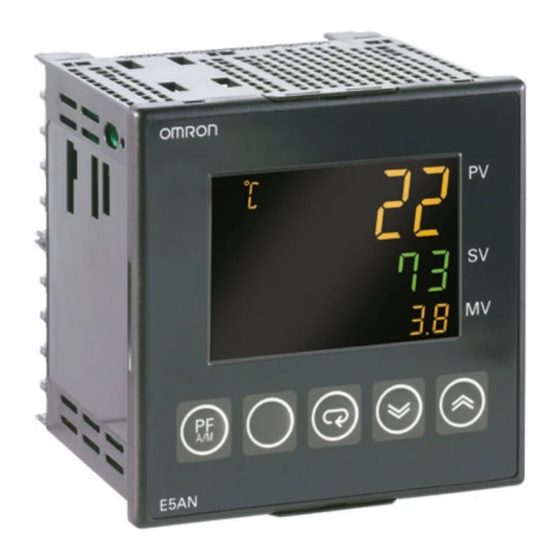
Names of Parts Section 1-1 Names of Parts 1-1-1 Front Panel E5CN/CN-U The front panel is the same for the E5CN and E5CN-U. Temperature unit No. 1 display Operation indicators No. 2 display Up Key Level Key Down Key Mode Key... -
Page 28: Explanation Of Indicators
Section 1-1 Names of Parts E5EN Operation indicators SUB1 SUB2 SUB3 Temperature unit No.1 display No.2 display OUT1 STOP No.3 display Operation indicators OUT2 MANU Up Key Mode Key Function Key/ Level Key Auto/Manual Key E5EN Down Key 1-1-2 Explanation of Indicators No. -
Page 29: Using The Keys
Names of Parts Section 1-1 3. OUT1 (Control Output 1) Lights when the control output function assigned to control output 1 turns ON. For a current output, however, OFF for a 0% output only. OUT2 (Control Output 2) Lights when the control output function assigned to control output 2 turns ON. -
Page 30: I/O Configuration And Main Functions
U or D key. This applies only to the parameter for the password to move to protect level. (Refer to page 146.) I/O Configuration and Main Functions 1-2-1 I/O Configuration E5CN Control Control output Temperature input Control output 1... - Page 31 Section 1-2 I/O Configuration and Main Functions E5CN-U Control Control output Temperature input Control output 1 section (heating) or analog input Control output (cooling) Heating/ cooling Alarm 3 Auxiliary output 2 Standard Alarm 2 Alarm 1 Auxiliary output 1 Input error...
- Page 32 2 3 4 5 2 3 4 1. Control Output 1 1. Applicable Controller R: Relay output CN: E5CN or E5CN-H Q: Voltage output (for driving SSR) 2. Function 1 C: Current output Blank: None Y: Long-life relay output (hybrid) *1 Q: Control output 2 (voltage for driv- 2.
- Page 33 Section 1-2 I/O Configuration and Main Functions E5AN/EN Temperature input Control Control output Control output 1 or analog input section (heating) Control output Control output 2 (cooling) (See note.) Heating/cooling External power (See note.) supply for ES1B Alarm 3 Alarm output 3 CT1 input Alarm 2 Alarm output 2...
-
Page 34: Main Functions
N: Available only to models released after January 2008. 1-2-2 Main Functions This section introduces the main E5CN/CN-U/AN/EN functions. For details on particular functions and how to use them, refer to SECTION 3 Basic Opera- tion and following sections. Input Sensor Types •... - Page 35 • Optimum PID constants can be set easily by performing AT (auto-tuning) or ST (self-tuning). Event Inputs • With the E53-CN@B@N2 for the E5CN or the E5AN/EN-@M@-500-N with the E53-AKB for the E5AN/EN, the following functions can be executed using event inputs: switching set points (multi-SP, 4 points max.), switch-...
- Page 36 I/O Configuration and Main Functions Section 1-2 RS-485 Interface Use the E53-CN@03N2 for the E5CN or the E53-EN03 for the E5AN/ RS-232C Interface Use the E53-EN01 for the E5AN/EN. Note (1) CompoWay/F is an integrated general-purpose serial communications protocol developed by OMRON. It uses commands compliant with the...
-
Page 37: Setting Level Configuration And Key Operations
Parameters are divided into groups, each called a level. Each of the set val- ues (setting items) in these levels is called a parameter. The parameters on the E5CN/CN-U/AN/EN are divided into the following 9 levels. When the power is turned ON, all of the display lights for approximately one second. - Page 38 Section 1-3 Setting Level Configuration and Key Operations Level Control in progress Control stopped Advanced function setting level Can be set. Calibration level Can be set. Communications setting level Can be set. Of these levels, the initial setting level, communications setting level, advanced function setting level, and calibration level can be used only when control is stopped.
-
Page 39: Selecting Parameters
Setting Level Configuration and Key Operations Section 1-3 Initial Setting Level • To move to the initial setting level from the operation level or the adjust- ment level, press the O Key for at least 3 seconds. The PV display flashes after one second. -
Page 40: Communications Function
The E5CN/AN/EN are provided with a communications function that enables parameters to be checked and set from a host computer. If the communica- tions function is required, use the E53-CN@03N2 with the E5CN, or the E53- EN03 or E53-EN01 with the E5AN/EN. For details on the communications function, see the separate Communications Manual Basic Type. - Page 41 The Protocol Setting parameter is displayed only when CompoWay/F commu- nications are being used. Setting Communications Match the communications specifications of the E5CN/AN/EN and the host Data computer. If a 1:N connection is being used, ensure that the communications specifications for all devices in the system (except the communications Unit No.) are the same.
-
Page 42: Preparations
SECTION 2 Preparations This section describes the work required to prepare the E5CN, E5AN, and E5EN Digital Temperature Controllers for operation, including installation and wiring. Installation........... . -
Page 43: Installation
Section 2-1 Installation Installation 2-1-1 Dimensions Unit: mm E5CN 48 × 48 E5CN-U (84.7) 44.8 × 44.8 48 × 48 70.5 14.2 79.2 E5AN 79.2 E5EN... - Page 44 Section 2-1 Installation 2-1-2 Panel Cutout Unit: mm E5CN/CN-U Individual Mounting Group Mounting (48 × number of Units − 2.5) +1.0 +0.6 E5AN Individual Mounting Group Mounting (96 × number of Units − 3.5) +1.0 +0.8 E5EN Individual Mounting Group Mounting (48 ×...
- Page 45 0.29 to 0.39 N·m. Mounting the Terminal Cover For the E5CN, make sure that the “UP” mark is facing up, and then attach the E53-COV17 Terminal Cover to the holes on the top and bottom of the Temper-...
- Page 46 Installation Section 2-1 E5AN/EN Mounting Mounting Bracket Panel Bracket Panel Terminal Cover (E53-COV16) Terminal Cover (E53-COV16) Waterproof packing Waterproof packing E5AN E5EN Mounting to the Panel 1,2,3... 1. For waterproof mounting, waterproof packing must be installed on the Controller. Waterproofing is not possible when group mounting several Controllers.
- Page 47 E5CN toward the rear case into position. While pushing the E5CN into place, push down on the hooks on the top and bot- tom surfaces of the rear case so that the hooks are securely locked in place.
- Page 48 Section 2-1 Installation E5AN/EN Tool insertion hole Tool insertion hole E5AN E5EN Flat-blade screwdriver (Unit: mm) 1,2,3... 1. Insert a flat-blade screwdriver into the two tool insertion holes (one on the top and one on the bottom) to release the hooks. 2.
- Page 49 Installation Section 2-1 3. When inserting the body of the Temperature Controller into the case, make sure the PCBs are parallel to each other, make sure that the sealing rubber is in place, and press the E5AN/EN toward the rear case until it snaps into position.
-
Page 50: Wiring Terminals
Section 2-2 Wiring Terminals Wiring Terminals Check the terminal arrangements for E5CN terminals 1 to 15 and E5AN/EN terminals 1 to 20 as marked on the product label and on the side of the case. 2-2-1 Terminal Arrangement E5CN Controllers... -
Page 51: Precautions When Wiring
• Use crimp terminals when wiring the terminals. • Tighten the terminal screws to a torque of 0.74 to 0.90 N·m, except for the E5CN-U, which is 0.5 N·m. • Use the following types of crimp terminals for M3.5 screws. - Page 52 E5AN/EN Control Output 1 • Outputs are sent from terminals 1 and 2 with the E5CN, from pins 4 to 6 with the E5CN-U, and from pins 3 and 4 with the E5AN/EN. The following diagrams show the available outputs and their internal equalizing circuits.
- Page 53 Section 2-2 Wiring Terminals − − Current Relay Voltage (for driving SSR) E5CN − − Relay Voltage (for driving SSR) Current E5CN-U − − Relay Voltage (for driving SSR) Current E5AN/EN • The following table shows the specifications for each output type.
- Page 54 440 to 470 V Control Output 2 • Outputs are sent from terminals 11, 12, 14, and 15 with the E5CN, and from pins 14 and 15 with the E5AN/EN. The following diagrams show the available outputs and their internal equalizing circuits.
- Page 55 With E5AN/EN, however, con- trol output 2 (voltage output for driving SSR) is functionally isolated from the internal circuits. • Control output 2 of the E5CN is a voltage output (for driving SSR) only, − −...
- Page 56 Section 2-2 Wiring Terminals • On the E5CN and E5CN-U, when heating/cooling control is used, auxil- iary output 2 becomes control output (cooling). • On the E5AN and E5EN, when heating/cooling control is used, auxiliary output 3 becomes control output (cooling).
- Page 57 16 (no polarity). E53-CN@@H@N2 E53-CN@HH@N2 E5AN/EN-@@H@-500-N E5AN/EN-@@HH@-500-N (for E5CN) Communications RS-485 • When communications are to be used with the E53-CN@03N2 (for E5CN) or E53-EN03 (for E5AN/EN), connect communications cable across ter- minals 11 and 12. B(+) B(+) A(−) RS-485 RS-485 A(−)
- Page 58 Section 2-2 Wiring Terminals E5AN/EN Host computer RS-485 Shield − E5AN/EN (No. 1) E5AN/EN (No. 31) RS-485 RS-485 Abbreviation Abbreviation A (−) A (−) B (+) B (+) A (−) A (−) A < B: [1] Mark B (+) B (+) A >...
- Page 59 ER (DTR) CS (CTS) • A 1:1 connection is used. The maximum cable length is 15 m. To extend the transmission path, use the OMRON Z3R RS-232C Optical Interface. • Use AWG24 (cross-sectional area: 0.205 mm ) to AWG14 (cross-sec- tional area: 2.081 mm...
-
Page 60: Using The Support Software Port
The E58-CIFQ1 USB-Serial Conversion Cable is required to make the connection. For information concerning the models that can be used with CX-Thermo, contact your OMRON sales representative. Procedure Use the following procedure to connect the Temperature Controller to the per- sonal computer using the USB-Serial Conversion Cable. - Page 61 Section 2-3 Using the Support Software Port • Installation When the Cable is connected with the personal computer, the OS detects the product as a new device. At this time, install the driver using the instal- lation wizard. For details on installation methods, refer to the user’s man- ual for the E58-CIFQ1 USB-Serial Conversion Cable.
-
Page 62: Basic Operation
SECTION 3 Basic Operation This section describes the basic operation of the E5CN, E5AN, and E5EN Digital Temperature Controllers, including key operations to set parameters and descriptions of display elements based on specific control examples. Initial Setting Examples ......... -
Page 63: Initial Setting Examples
Section 3-1 Initial Setting Examples Initial Setting Examples Initial hardware setup, including the sensor input type, alarm types, control periods, and other settings, is done using parameter displays. The O and M Keys are used to switch between parameters, and the amount of time that you press the keys determines which parameter you move to. - Page 64 Section 3-1 Initial Setting Examples Example 2 Input type: 9 (T thermocouple, −200°C to 400°C) Control method: PID control PID constants found using auto- tuning (AT). Alarm type: 2 upper limit Alarm value 1: 30°C Set point: 150°C Setup Procedure Power ON Power ON Operation Level...
-
Page 65: Setting The Input Type
Section 3-2 Setting the Input Type Setting the Input Type The Controller supports four input types: platinum resistance thermometer, thermocouple, infrared temperature sensor, and analog inputs. Set the input type that matches the sensor that is used. In the product specifications, there are models with thermocouple/resistance thermometer inputs (universal inputs) and models with analog input. - Page 66 Setting the Input Type Section 3-2 List of Input Types Input type Specifications Set value Input temperature setting range −200 to 850 (°C)/−300 to 1,500 (°F) Controllers Platinum resistance Pt100 with Ther- thermometer −199.9 to 500.0 (°C)/−199.9 to 900.0 (°F) mocouple/ 0.0 to 100.0 (°C)/0.0 to 210.0 (°F) Resistance...
-
Page 67: Selecting The Temperature Unit
Selecting the Temperature Unit Section 3-3 Selecting the Temperature Unit 3-3-1 Temperature Unit • Either ° C or ° F can be selected as the temperature unit. • Set the temperature unit in the Temperature Unit parameter of the initial setting level. -
Page 68: Direct And Reverse Operation
Section 3-5 Setting Output Specifications 3-5-2 Direct and Reverse Operation • Direct operation increases the manipulated variable whenever the pro- cess value increases. Reverse operation decreases the manipulated vari- able whenever the process value increases. Manipulated variable Manipulated variable 100% 100% Set Value High... -
Page 69: Assigned Output Functions
Alarm 2 sub3 Auxiliary Output 3 Assignment Alarm 3 (E5AN/EN only) • Each output is automatically initialized as shown below by changing the control mode. Example: E5CN Parameter name Symbol Without control output 2 With control output 2 Standard Heating/cooling... - Page 70 Section 3-5 Setting Output Specifications ■ Alarms It will be specified in this section when an alarm must be assigned, i.e., when an alarm must be set for the Control Output 1 or 2 Assignment parameters, or for the Auxiliary Output 1 or 3 Assignment parameters. For example, if alarm 1 is set for the Control Output 1 Assignment parameter, then alarm 1 has been assigned.
- Page 71 Section 3-5 Setting Output Specifications 8. Select the Control Output 2 Assignment parameter by pressing the M Advanced Function Setting Level Key. Control Output out2 2 Assignment 9. Press the U or D Key to set c-o. out2 (When h-c is selected for the Standard or Heating/Cooling parameter, the setting will be c-o.) 10.
-
Page 72: Setting The Set Point (Sp)
Setting the Set Point (SP) Section 3-6 Auxiliary output Auxiliary Indicators functions 1 to 3 output (SUB1 to SUB3) Open in Alarm Not lit • The alarm output will turn OFF (i.e., the relay contacts will open) when power is interrupted and for about two seconds after the power is turned ON regardless of the setting of the Auxiliary Output 1 to 3 Open in Alarm parameter. -
Page 73: Using On/Off Control
Section 3-7 Using ON/OFF Control Using ON/OFF Control In ON/OFF control, the control output turns OFF when the temperature being controlled reaches the preset set point. When the manipulated variable turns OFF, the temperature begins to fall and the control turns ON again. This oper- ation is repeated over a certain temperature range. -
Page 74: Settings
Section 3-7 Using ON/OFF Control Parameters Symbol Parameter: level Application s-hc Standard or Heating/Cooling: Initial setting level Specifying control method cntl PID ON/OFF: Initial setting level Specifying control method orev Direct/Reverse Operation: Initial setting level Specifying control method c-db Dead Band: Adjustment level Heating/cooling control Hysteresis (Heating): Adjustment level ON/OFF control... -
Page 75: Determining Pid Constants (At, St, Manual Setup)
Section 3-8 Determining PID Constants (AT, ST, Manual Setup) Setting the Hysteresis ° Operating Procedure Set the hysteresis to 2.0 1. Press the O Key to move from the operation level to the adjustment level. Operation Level Adjustment Level 2. The Adjustment Level Display parameter will be displayed in the adjust- ment level. - Page 76 Section 3-8 Determining PID Constants (AT, ST, Manual Setup) AT Operations AT is started when either at-2 (100% AT) or at-1 (40% AT) is specified for the AT Execute/Cancel parameter. During execution, the AT Execute/Cancel parameter on the No. 1 display flashes. When AT ends, the AT Execute/Can- cel parameter turns OFF, and the No.
-
Page 77: St (Self-Tuning)
Section 3-8 Determining PID Constants (AT, ST, Manual Setup) ■ 100% AT Operation will be as shown in the following diagram, regardless of the devia- tion (DV) at the start of AT execution. To shorten the AT execution time, select 100% AT. -
Page 78: St Stable Range
Section 3-8 Determining PID Constants (AT, ST, Manual Setup) Note PID Constants When control characteristics are already known, PID constants can be set directly to adjust control. PID constants are set in the Proportional Band (P), Integral Time (I), and Derivative Time (D) parameters in the adjustment level. Operating Procedure This procedure executes self-tuning (ST). -
Page 79: Rt (Robust Tuning)
Section 3-8 Determining PID Constants (AT, ST, Manual Setup) This procedure sets the ST stable range to 20.0 ° C. 1. Select the ST Stable Range parameter by pressing the M Key in the ad- Advanced Function Setting Level vanced function setting level. ST Stable st-b Range... - Page 80 Section 3-8 Determining PID Constants (AT, ST, Manual Setup) • When the temperature (PV) falls short of the set point for the PID con- stants when using AT or ST in normal mode, executing AT or ST in RT mode tends to improve performance. Temperature Temperature Set value...
-
Page 81: Manual Setup
Section 3-8 Determining PID Constants (AT, ST, Manual Setup) 7. To return to the operation level, press the O Key for at least one second. Operation Level PV/SP 3-8-4 Manual Setup Individual PID constants can be manually set in the Proportional Band, Inte- gral Time, and Derivative Time parameters in the adjustment level. -
Page 82: Alarm Outputs
Alarm Outputs • Alarms can be used by the E5CN-@2@@@ (2 auxiliary outputs), E5AN/ EN-@3@@@ (3 auxiliary outputs), the E5CN-@1@@@U (1 auxiliary out- put), or the E5CN-@2@@@U (2 auxiliary outputs). Alarms can also be used by setting the Control Output 1 Assignment or Control Output 2 Assignment parameter to alarm 1 to 3. - Page 83 Section 3-9 Alarm Outputs Set value Alarm type Alarm output operation When alarm value X When alarm value X is positive is negative Lower-limit 4 (See note Upper- and lower-limit See note 3. range 5 (See note Upper- and lower-limit See note 4.
-
Page 84: Alarm Values
Section 3-9 Alarm Outputs • Set the alarm type independently for each alarm in the Alarm 1 to 3 Type parameters in the initial setting level. The default is 2 (Upper-limit alarm). 3-9-2 Alarm Values • Alarm values are indicated by “X” in the table on the previous page. When Alarm Lower al1l Limit Value... -
Page 85: Using Heater Burnout, Heater Short, And Heater Overcurrent Alarms
Section 3-10 Using Heater Burnout, Heater Short, and Heater Overcurrent Alarms PV Change Rate Alarm The change width can be found for PV input values in any set period. Differ- ences with previous values in each set period are calculated, and an alarm is output if the result exceeds the alarm value. - Page 86 Section 3-10 Using Heater Burnout, Heater Short, and Heater Overcurrent Alarms Control output (heating) status Power to heater HB alarm HS alarm Heater overcurrent output output alarm output Control output Operation (heating) indicator Normal Heater overcurrent status (See note 3.) Toff (See note 3.) (See note 4.)
-
Page 87: Installing Current Transformers (Ct)
• This function can be used with E5@N models that have the HB alarm, HS alarm, and OC alarm. For the E5CN, connect the CT in advance to terminals 14 and 15 (CT1), or 13 and 15 (CT2). For the E5AN/EN, connect the CT in advance to ter- minals 14 and 15 (CT1) or 15 and 16 (CT2). -
Page 88: Calculating Detection Current Values
Section 3-10 Using Heater Burnout, Heater Short, and Heater Overcurrent Alarms Load (such as a heater) AC line Product To CT input Product To CT input 3. V connecting lines: Refer to the following diagram for CT installation posi- tions. Note Heater voltage fluctuations are not considered here, so be take that into account when setting the detection current. -
Page 89: Application Examples
Section 3-10 Using Heater Burnout, Heater Short, and Heater Overcurrent Alarms • The setting range is 0.1 to 49.9 A. Heater burnout, HS, and heater over- current are not detected when the set value is 0.0 or 50.0. When the set value is 0.0, the heater burnout alarm is always OFF, the HS alarm is always ON, and the heater overcurrent alarm is always ON. - Page 90 Section 3-10 Using Heater Burnout, Heater Short, and Heater Overcurrent Alarms Three-phase Heaters Delta Connecting Lines Example: Using Three 200-VAC, 2-kW Heaters Normal 17.3 A→ 200 V 17.3 A→ Load 200 V 200 V Product To CT input 17.3 A→ Product To CT input The current when each phase is normal is 17.3 A ( ≈...
- Page 91 Section 3-10 Using Heater Burnout, Heater Short, and Heater Overcurrent Alarms Star Connecting Lines Example: Using Three 200-VAC, 2-kW Heaters Normal 5.8 A→ 200 V Load (such as a heater) 200 V 5.8 A→ 200 V Product To CT input 5.8 A→...
- Page 92 Section 3-10 Using Heater Burnout, Heater Short, and Heater Overcurrent Alarms V Connecting Lines Example: Using Two 200-VAC, 2-kW Heaters Normal 10 A→ Product 200 V To CT input 17.3 A→ 200 V 200 V 10 A Product To CT input Burnout 5 A→...
-
Page 93: Settings: Hb Alarm
Section 3-10 Using Heater Burnout, Heater Short, and Heater Overcurrent Alarms 3-10-5 Settings: HB Alarm To activate the heater burnout alarm, set the HB ON/OFF parameter to ON in the advanced function setting level and set the Heater Burnout Detection 1 and Heater Burnout Detection 2 parameters in the adjustment level. -
Page 94: Settings: Heater Short Alarm
Section 3-10 Using Heater Burnout, Heater Short, and Heater Overcurrent Alarms 9. For this example, set 2.5. To return to the operation level, press the O Key for less than one second. 3-10-6 Settings: Heater Short Alarm To activate the HS alarm, set the HS Alarm Use parameter to ON in the advanced function setting level and set the HS Alarm 1 and HS Alarm 2 parameters in the adjustment level. -
Page 95: Settings: Heater Overcurrent Alarm
Section 3-10 Using Heater Burnout, Heater Short, and Heater Overcurrent Alarms ■ HS Alarm Settings 5. Press the O Key for at least one second to move from the advanced Operation Level function setting level to the initial setting level. Press the O key again for PV/SP at least one second to move to the operation level. - Page 96 Using Heater Burnout, Heater Short, and Heater Overcurrent Alarms Section 3-10 Advanced Function Setting Level The top parameter in the advanced function setting level is displayed. Move to the init Advanced Function Setting Level 4. Press the M Key to select the Heater Overcurrent Use parameter. Heater Check that this parameter is set to ON (the default), and then set the Overcurrent...
-
Page 97: Setting The No. 3 Display
Setting the No. 3 Display Section 3-11 3-11 Setting the No. 3 Display This section describes how to set the No. 3 Display (E5AN/EN). The Multi-SP, MV, or soak time remain can be displayed on the No. 3 display. 3-11-1 PV/SP Display Selection The following table shows the set values and display contents for the PV/SP Display selection. - Page 98 Section 3-11 Setting the No. 3 Display Operating Procedure This procedure displays PV/SP/MV and PV/SP/Multi-SP on the Process Value/Set Point display. The PV/SP Display Screen Selection parameter is set to 2. 1. Press the O Key for at least three seconds to move from the operation Operation Level level to the initial setting level.
- Page 99 Setting the No. 3 Display Section 3-11...
-
Page 100: Applications Operations
This section describes scaling, the SP ramp function, and other special functions that can be used to make the most of the functionality of the E5CN, E5AN, and E5EN Digital Temperature Controllers. Shifting Input Values.......... - Page 101 4-15 Using the Simple Program Function ....... . 4-15-1 Simple Program Function ....... . . 4-15-2 Operation at the Program End .
-
Page 102: Shifting Input Values
Shifting Input Values Section 4-1 Shifting Input Values 4-1-1 Shifting Inputs The input shift matched to the sensor currently selected in the Input Type parameter is displayed. • A 2-point shift is applied for infrared temperature sensors. A 2-point shift can also be used if the Input Shift Type parameter (advanced function set- ting level) is set to INS2 for a thermocouple or platinum resistance ther- mometer. -
Page 103: How To Calculate Input Shift Values For A 2-Point Shift
3. The E53-CN@@P@N2 (for E5CN), E5AN-@@P@-N, or E5EN-@@P@-N has a built-in external power supply for ES1B Infrared Temperature Sen- sors. These E5CN models can be used as the power supply when using ES1B. When ES1B are used with other E5CN models, provide a separate... - Page 104 Sensor Power supply (B) Thermometer Output (A) E5CN/AN/EN Temperature Controller Figure 1 Offset Configuration for an Infrared Temperature Sensor Method for a 1-point Shift 1,2,3... 1. In the configuration shown in Figure 1, bring the set point to near the value at which the temperature of the control target is to be controlled.
- Page 105 Section 4-1 Shifting Input Values Method for a 2-point Use a 2-point input shift if you want to increase the accuracy of the readout Shift values across the range of the Sensor. 1,2,3... 1. Shift the Controller readout at two points, near room temperature and near the value at which the temperature of the control target is to be controlled.
-
Page 106: Alarm Hysteresis
Section 4-2 Alarm Hysteresis Lower-limit Temperature Input Shift Value 0 − 40 × {(110 − 105) − (25 − 40)} + (25 − 40) = −27.3 (°C) insl = 105 − 40 Upper-limit Temperature Input Shift Value 260 − 40 Upper-limit insh ×... -
Page 107: Setting Scaling Upper And Lower Limits For Analog Inputs
Section 4-3 Setting Scaling Upper and Lower Limits for Analog Inputs • Use an event input. For details on setting the PF Key, refer to 4-19 Setting the PF Key. For details on setting events, refer to 4-5 Using Event Inputs. Summary of Alarm The following figure summarizes the operation of alarms when the Alarm Type Operation... -
Page 108: Executing Heating/Cooling Control
8. To return to the operation level, press the O Key for one second. Executing Heating/Cooling Control 4-4-1 Heating/Cooling Control Heating/cooling control can be used on the E5CN-@M@-500 (with an E53- CNQ@@N2), E5CN-@2M@-500, E5AN-@3@M@-500-N or E5EN-@3@M@- 500-N. Heating/cooling control operates when h-c (heating/cooling) is selected for the Standard or Heating/Cooling parameter. - Page 109 Alarm 2 sub3 Auxiliary Output 3 Assignment Alarm 3 (E5AN/EN only) Each output assignment is automatically initialized as shown below when the control mode is changed. Example: E5CN Parameter name Symbol Without control output 2 With control output 2 Standard Heating/cooling...
- Page 110 Section 4-4 Executing Heating/Cooling Control Dead Band • For heating/cooling control, the dead band is set with the set point as its center. The dead band width is the set value of the Dead Band parameter (adjustment level). Setting a negative value produces an overlapping band.
-
Page 111: Settings
Section 4-4 Executing Heating/Cooling Control oscillating waves. If that occurs, increase the proportional band or the cooling coefficient to improve control. 4-4-2 Settings To set heating/cooling control, set the Standard or Heating/Cooling, Dead Band, and Cooling Coefficient parameters. Setting Heating/Cooling Control Operating Procedure Standard or heating/cooling = Heating/cooling 1. -
Page 112: Using Event Inputs
Event Input Assignment (1 and 2) parameters (initial setting level). • Event inputs can be used on the following models: E5CN-@M@-500 with the E53-CN@B@N2 for the E5CN E5AN/EN-@M@-500-N with the E53-AKB for the E5AN/EN • When using event inputs to switch the multi-SP, the event input assign- ment display will not appear. -
Page 113: How To Use The Multi-Sp Function
Section 4-5 Using Event Inputs 4-5-2 How to Use the Multi-SP Function The multi-SP function allows you to set up to four set points (SP 0 to 3) in the adjustment level. The set point can be switched by operating the keys on the front panel or by using external input signals (event inputs). -
Page 114: Operation Commands Other Than Multi-Sp
3. Use the U Key to set the parameter to 2. ev-m Set points 0, 1, 2 and 3 will be set according to the ON/OFF states of event inputs 1 and 2. E5AN/EN E5CN − − 4-5-4 Operation Commands Other than Multi-SP The following table shows the functions assigned when an Event Input Assignment (1 or 2) is displayed. - Page 115 Section 4-5 Using Event Inputs Executing Run/Stop When the Event Input Assignment 1 or Event Input Assignment 2 parameter Control is set to STOP (RUN/STOP), control is started when event input 1 or 2 turns OFF. Control is stopped when the input turns ON. Alarm outputs, however, will be according to the process value.
-
Page 116: Setting The Sp Upper And Lower Limit Values
Section 4-6 Setting the SP Upper and Lower Limit Values Switching 40% AT When AT-1 (40% AT Execute/Cancel) is set for either the Event Input Assign- Execute/Cancel ment 1 or Event Input Assignment 2 parameter, 40% AT will be executed when event input 1 or 2 turns ON and will be cancelled when the input turns OFF. -
Page 117: Setting
Section 4-6 Setting the SP Upper and Lower Limit Values Input setting range Set point limiter Setting range Set point (Cannot be set.) Upper limit value changed Upper limit value changed Set point Input type changed Set point Set value Upper/lower limit values (Can be set.) Sensor upper/lower limit values... -
Page 118: Using The Sp Ramp Function To Limit The Sp Change Rate
Section 4-7 Using the SP Ramp Function to Limit the SP Change Rate Setting the Set Point Lower-limit Value Set Point Lower Limit = − 100 Operating Procedure 1. Select the Set Point Lower Limit parameter in the initial setting level. Set Point sl-l Lower Limit... - Page 119 Section 4-7 Using the SP Ramp Function to Limit the SP Change Rate Operation at Startup If the SP ramp function is enabled when the Controller is turned ON or when switching from STOP to RUN mode, the process value reaches the set point using the SP ramp function in the same way as when the set point is changed.
-
Page 120: Moving To The Advanced Function Setting Level
Section 4-8 Moving to the Advanced Function Setting Level Moving to the Advanced Function Setting Level To move to the advanced function setting level, you must first cancel the pro- tection applied by the Initial Setting/Communications Protect parameter. In the default setting, the advanced function setting level is protected and you cannot move to this setting level. -
Page 121: Using The Key Protect Level
Section 4-9 Using the Key Protect Level Using the Key Protect Level 4-9-1 Protection • To move to the protect level, press the O and M Keys simultaneously for at least three seconds in operation level or adjustment level. (See note.) Note The key pressing time can be changed in the Move to Protect Level Time parameter (advanced function setting level). -
Page 122: Entering The Password To Move To The Protect Level
Section 4-9 Using the Key Protect Level • The default is OFF. • The all protect indication ( ) will light when setting change protect is set. PF Key Protect This protect level enables or disables PF Key operations. Set value Description pfpt PF Key enabled. - Page 123 Note Protection cannot be cleared or changed without the password. Be careful not to forget it. If you forget the password, contact your OMRON sales representative. Communications • The Write Variable operation command can be used via communications Operation Command to write the password to the Move to Protect Level parameter.
-
Page 124: Pv Change Color
Section 4-10 PV Change Color 4-10 PV Change Color 4-10-1 PV Color Change Function Use the PV color change function to change the color of the PV display (No. 1 display). There are three display colors, orange, red, and green, and you can select from the following three modes and eight functions. -
Page 125: Setting
Section 4-10 PV Change Color PV Stable Band When the mode to link to the PV stable band is selected, the PV display color will change according to whether the present value (PV) is lower than, within, PV Stable pv-b Band or higher than the PV stable band shown in the following figure. - Page 126 Section 4-10 PV Change Color 5. Press the U Key to set the parameter to r-gr. colr r-g.r 6. Select the PV Stable Band parameter by pressing the M Key. Advanced Function Setting Level PV Stable pv-b Band 7. Use the U Key to set the parameter to 15.0. pv-b 15.0 8.
-
Page 127: Alarm Delays
Section 4-11 Alarm Delays 4-11 Alarm Delays 4-11-1 Alarm Delays • Delays can be set for the alarm outputs. ON and OFF delays can be set separately for alarms 1, 2, and 3. The ON and OFF delays for alarm 1 function only for the alarm function. - Page 128 Section 4-11 Alarm Delays Note (1) The defaults are 0, i.e., the ON and OFF delays are disabled. (2) The parameters are displayed when alarm functions are assigned and when the alarm type is set to any type but 0 (none), 12: LBA, or 13: PV change rate alarm.
-
Page 129: Loop Burnout Alarm
Section 4-12 Loop Burnout Alarm 9. Press the O Key for at least one second to move from the initial setting Operation Level level to the operation level. PV/SP 4-12 Loop Burnout Alarm 4-12-1 Loop Burnout Alarm (LBA) • With a loop burnout alarm, there is assumed to be an error in the control loop if the control deviation (SP −... - Page 130 Section 4-12 Loop Burnout Alarm • If the set point is so high or low that it cannot be reached even with a sat- urated manipulated variable, a temperature deviation may remain even in a steady state and a loop burnout may be detected. •...
- Page 131 Section 4-12 Loop Burnout Alarm Determining the LBA • To manually set the LBA detection time, set the LBA Detection Time Detection Time parameter to twice the LBA reference time given below. 1,2,3... 1. Set the output to the maximum value. 2.
- Page 132 Section 4-12 Loop Burnout Alarm 3. Press the U Key to set the parameter to 12. Initial Setting Level alt1 4. Select the Move to Advanced Function Setting Level parameter by press- Move to Ad- amov ing the M Key. (For details on moving between levels, refer to 4-8 Moving vanced Function Setting Level to the Advanced Function Setting Level.)
-
Page 133: Performing Manual Control
Section 4-13 Performing Manual Control 4-13 Performing Manual Control 4-13-1 Manual Operation • The manipulated variable can be set in manual mode if the PV/MV param- eter is displayed in the manual control level. The final MV used in auto- matic mode will be used as the initial manual MV when moving from automatic mode to manual mode. - Page 134 Section 4-13 Performing Manual Control Manual MV Limit When the Manual MV Limit Enable parameter is set to ON (enabled), the MV Enable limits will function and the setting range for the Manual MV parameter will be between the MV upper limit and the MV lower limit. When the parameter is set to OFF (disabled), MV limits will not function.
- Page 135 Section 4-13 Performing Manual Control Using the PF Key to • When the PF Setting parameter is set to A-M (Auto/Manual), pressing the Move to the Manual PF Key for at least one second while in the adjustment or operation level will change the mode to manual mode and move to the manual control Control Level level.
- Page 136 Performing Manual Control Section 4-13 6. Use the U Key to set the parameter to ON. amad 7. Press the O Key for at least one second to move from the advanced Initial Setting Level function setting level to the initial setting level. Input Type in-t 8.
-
Page 137: Using The Transfer Output
Using the Transfer Output Section 4-14 4. Press the D Key to enter the password ( − 169), and move from the initial Advanced Function Setting Level setting level to the advanced function setting level. Parameter init Initialization 5. Select the Auto/Manual Select Addition parameter by pressing the M Advanced Function Setting Level Key. - Page 138 Section 4-14 Using the Transfer Output • The operation is shown in the following table. Control output 1 Control output 2 Transfer output destination Current output None, relay output, voltage Control output 1 output (for driving SSR) Relay output, voltage out- None, relay output, voltage None put (for driving SSR)
- Page 139 Using the Transfer Output Section 4-14 Transfer Scaling • Reverse scaling is possible by setting the Transfer Output Lower Limit parameter larger than the Transfer Output Upper Limit parameter. If the Transfer Output Lower Limit and Transfer Output Upper Limit parameters are set to the same value when 4 to 20 mA is set, the transfer output will be output continuously at 0% (4 mA).
-
Page 140: Using The Simple Program Function
Section 4-15 Using the Simple Program Function 3. Press the U Key to select sp (set point). tr-t 4. Select the Transfer Output Upper Limit parameter by pressing the M Key. Initial Setting Level Transfer Output tr-h Upper Limit 1300 5. - Page 141 Section 4-15 Using the Simple Program Function • The program will start when the Program Start parameter is changed from RSET to STRT. END will be displayed on the No. 2 display and the output assigned as the program end output will turn ON after the time set in the Soak Time parameter has expired in the wait band.
- Page 142 Using the Simple Program Function Section 4-15 Starting Method Any of the following three methods can be used to start the simple program. • Setting the Program Start parameter to STRT. • Turning ON an event input. (The program start must be assigned to an event input.
-
Page 143: Operation At The Program End
Section 4-15 Using the Simple Program Function 4-15-2 Operation at the Program End Display at the Program End When the program ends, the process value will be displayed on the No. 1 dis- play (see note) and the set point and “end” will be alternately displayed on the No. - Page 144 Section 4-15 Using the Simple Program Function Operation Level PV/SP 1. Press the O Key for at least three seconds to move from the operation Initial Setting Level level to the initial setting level. Input Type in-t 2. Select the Program Pattern parameter by pressing the M Key. Initial Setting Level Program Pattern ptrn...
-
Page 145: Application Example Using A Simple Program
Section 4-15 Using the Simple Program Function 4-15-3 Application Example Using a Simple Program The program will be started by changing the setting of the Program Start parameter. The following example shows using a simple program with the pro- gram pattern set to STOP. Wait band Set point Soak time... -
Page 146: Output Adjustment Functions
Output Adjustment Functions Section 4-16 4-16 Output Adjustment Functions 4-16-1 Output Limits • Output limits can be set to control the output using the upper and lower limits to the calculated MV. • The following MV takes priority over the MV limits. Manual MV (See note.) MV at stop MV at PV error... -
Page 147: Using The Extraction Of Square Root Parameter
Using the Extraction of Square Root Parameter Section 4-17 4-16-3 MV at PV Error • The MV to be output for input errors can be set. The MV at stop takes priority when stopped and the manual MV takes pri- ority in manual mode. - Page 148 Section 4-17 Using the Extraction of Square Root Parameter Extraction of square root 100% FS Extraction of square root low-cut point 100% FS Argument 1 (Input Data) Parameter name Setting rage Unit Default Extraction of Square OFF: Disabled, ON: Enabled Root Enable Extraction of Square 0.0 to 100.0...
-
Page 149: Setting The Width Of Mv Variation
Setting the Width of MV Variation Section 4-18 7. Use the U Key to set the parameter to − 10.0. Extraction of sqrp Square Root Low-cut Point 10.0 8. Press the O Key to return to the operation level. Operation Level PV/SP 4-18 Setting the Width of MV Variation MV Change Rate Limit... - Page 150 Section 4-18 Setting the Width of MV Variation 3. Use the U Key to select 2-PID control. PID·ON/OFF cntl 4. Press the M Key to select the ST parameter. 5. Press the D Key to select OFF. 6. Press the O Key for at least one second to move from the initial setting Operation Level level to the operation level.
-
Page 151: Setting The Pf Key
Section 4-19 Setting the PF Key 4-19 Setting the PF Key 4-19-1 PF Setting (Function Key) PF Setting • Pressing the PF Key for at least one second executes the operation set in the PF Setting parameter (E5AN/EN only). Set value Symbol Setting Function... - Page 152 Setting the PF Key Section 4-19 Setting Remarks value Monitor/Setting Symbol Disabled PV/SP/Multi-SP Can be set. (SP) PV/SP/MV (See note.) Can be set. (SP) PV/SP /Soak time remain Can be set. (SP) Proportional band (P) Can be set. Integral time (I) Can be set.
-
Page 153: Counting Control Output On/Off Operations
Section 4-20 Counting Control Output ON/OFF Operations 3. Press the D Key to enter the password ( − 169). It is possible to move to Advanced Function Setting Level the advanced function setting level by either pressing the M Key or wait- Parameter init ing two seconds without pressing any key. - Page 154 Section 4-20 Counting Control Output ON/OFF Operations Control Output ON/ This function is not displayed when the Control Output 1 ON/OFF Alarm Set- OFF Counter Monitor ting and the Control Output 2 ON/OFF Alarm Setting parameter are set to 0, or when the control outputs are set for linear outputs.
-
Page 155: Displaying Pv/Sv Status
Section 4-21 Displaying PV/SV Status Operating Procedure This procedure sets the Control Output 1 ON/OFF Alarm Setting parameter to 10 (1,000 times). 1. Press the O Key for at least three seconds to move from the operation Initial Setting Level level to the initial setting level. - Page 156 Section 4-21 Displaying PV/SV Status Set value Symbol Function alm3 Alarm 3 ALM3 is alternately displayed during Alarm 3 status. Alarm 1 to 3 OR status ALM is alternately displayed when Alarm 1, 2, or 3 is set to ON. Heater Alarm (See note.) HA is alternately displayed when a heater burnout alarm, HS alarm, or heater over-...
-
Page 157: Logic Operations
Section 4-22 Logic Operations Operating Procedure This procedure sets the PV Status Display Function parameter to ALM1. 1. Press the O Key for at least three seconds to move from the operation Initial Setting Level level to the initial setting level. Input Type in-t Initial Setting Level... -
Page 158: Using Logic Operations
Section 4-22 Logic Operations 4-22-2 Using Logic Operations Logic operations are set using the CX-Thermo. Starting Logic There are two ways to start logic operations. Operations • Select Logic Operation Editor from the CX-Thermo tree, and click the Start Button. •... - Page 159 Section 4-22 Logic Operations Example: Selecting Library 1 2. Switching Work Bit Operations Select the work bit logic operations from the Operation of Work Bit 1 to Op- eration of Work Bit 8 Tab Pages. 3. Selecting the Operation Type From one to four operations are supported.
- Page 160 Section 4-22 Logic Operations • Operation 3 A or B or C or D When condition A, B, C or D is satisfied • Operation 4 A and B and C and D When conditions A, B, C and D are all satisfied...
- Page 161 Section 4-22 Logic Operations 4. Selecting Input Assignments Select the input assignment for the work bit logic operation from the follow- ing settings. Parameter Setting range name Work Bit 1 Input 0: Always OFF Assignment A 1: Always ON 2: ON for one cycle when power is turned ON 3: Event input 1 (external input) (See note 1.) 4: Event input 2 (external input) (See note 1.) 5: Event input 3 (external input) (See note 1.)
- Page 162 Section 4-22 Logic Operations (2) Turns ON when either the control output 1 or 2 ON/OFF count alarm is 5. Switching between Normally Open and Normally Closed for Inputs A to D Click the condition to switch between normally open and normally closed inputs A to D.
- Page 163 Section 4-22 Logic Operations Note The event input data can be changed from the default setting even if there is no event input terminal (external input). By changing the default setting, the event input assignment parameters will be dis- played at the Controller display and can be set from the Controller. 12.
- Page 164 Section 4-22 Logic Operations 3. Set the operation by selecting one of the following: Work bit 1 input assignment A = 4: Event input 2 (ex- ternal input) Work bit 1 input assignment B = 0: Always OFF Work bit 1 input assignment C = 0: Always OFF Work bit 1 input assignment D = 0: Always OFF 4.
- Page 165 Section 4-22 Logic Operations 3. Select Library 1 from the library list, and then click the OK Button. Confirm the following settings, and then click the OK Button. Work bit 1 operation type: Operation 1 Work bit 1 input assignment A = 7: Alarm 1 Work bit 1 input assignment B = 19: Invert for RUN/ STOP Work bit 1 input assignment C = 0: Always OFF...
-
Page 166: Parameters
SECTION 5 Parameters This section describes the individual parameters used to setup, control, and monitor operation. Conventions Used in this Section ........5-1-1 Meanings of Icons Used in this Section . -
Page 167: Conventions Used In This Section
Protected parameters are not dis- played regardless of the conditions for use, but the settings of these parame- ters are still valid. The E5CN must be in operation, and AT Execute/Cancel control must be 2-PID control. -
Page 168: Protect Level
Section 5-2 Protect Level Protect Level Four levels of protection are provided on the E5CN, operation/adjustment pro- tect, initial setting/communications protect, setting change protect, and PF key protect (E5AN/EN only). These protect levels prevent unwanted operation of the keys on the front panel in varying degrees. - Page 169 Protect Level Section 5-2 The Password to Move to Protect pmov Move to Protect Level Level password must not be set to 0. The password to move to the protect level is entered for this parameter. • The password to move to the protect level (i.e., the password set for the Password to Move to Protect Level parameter) is entered for this parame- ter.
- Page 170 Section 5-2 Protect Level The Event Input Assignment 1 and 2 wtpt Setting Change Protect parameters must not be set to “set- ting change enable/disable.” This parameter specifies the range of data to be protected. The shaded cell indicates the default. ■...
- Page 171 • Set this parameter to 0 when no password is to be set. ■ Related Parameters Move to protect level (protect level): Page 144 Note Protection cannot be cleared or changed without the password. Be careful not to forget it. If you forget the password, contact your OMRON sales representa- tive.
-
Page 172: Operation Level
Operation Level Section 5-3 Operation Level Display this level to perform control operations on the E5CN. You can set alarm values, monitor the manipulated variable, and perform other operations in this level. In the advanced function setting level, you can set a parameter to hide or show the set points. - Page 173 Section 5-3 Operation Level Operation Level Page Page Process Value Alarm Value 1 al-1 Process Value/Set Point Alarm Value Upper al1h (See note.) Limit 1 Auto/Manual Switch Alarm Value Lower al1l Limit 1 Multi-SP Set Alarm Value 2 m-sp al-2 Point Setting Set Point During SP sp-m...
- Page 174 Section 5-3 Operation Level The Additional PV Display parameter Process Value must be set to ON. The process value is displayed on the No. 1 display, and nothing is displayed on the No. 2 and No. 3 (E5AN/EN only) displays. Function Monitor range Unit...
- Page 175 Section 5-3 Operation Level Set value Display contents PV/SP/MV and PV/SP/Multi-SP are displayed in order. Only PV/SP/Multi-SP are displayed. PV/SP/MV are displayed PV/SP/Multi-SP and PV/SP/Soak time remain are displayed in order. PV/SP/MV and PV/SP/Soak time remain are displayed in order. Only PV/SP/Soak time remain are displayed.
- Page 176 Section 5-3 Operation Level Multi-SP Set Point Setting The Multi-SP Uses parameter must m-sp be set to ON. (Set Points 0 to 3) To use the multi-SP function, preset the four set points (SP 0 to 3) in the adjustment level, and then switch the set point either by operating the keys or by using external input signals (event inputs).
- Page 177 Section 5-3 Operation Level Heater burnout, HS alarm, and heater overcurrent detection must be supported. Heater Current 1 Value Monitor Alarm 1 must be assigned. The Heater Burnout Detection or Heater Overcurrent Use parameter must be set to ON. This parameter measures the heater current from the CT input used for detecting heater burnout.
- Page 178 Section 5-3 Operation Level Heater burnout, HS alarm, and heater overcurrent detection must be supported (two CTs). Heater Current 2 Value Monitor Alarm 1 must be assigned. The Heater Burnout Detection or Heater Overcurrent Use parameter must be set to ON. This parameter measures the heater current from the CT input used for detecting heater burnout.
- Page 179 Section 5-3 Operation Level Heater burnout, HS alarms, and heater overcurrent detection must be lcr1 Leakage Current 1 Monitor supported. The HS Alarm Use parameter must be set to ON. This parameter measures the heater current from the CT input used for detecting SSR short-circuits.
- Page 180 Section 5-3 Operation Level The Program Pattern parameter prst Program Start must not be set to OFF. This parameter starts and stops the simple program function. • The RUN/STOP status will automatically switch to RUN when this param- eter is set to STRT. Function •...
- Page 181 Section 5-3 Operation Level The Event Input Assignment 1 and 2 RUN/STOP parameters must not be set to “RUN/ STOP.” This parameter starts and stops the control operation. When run (RUN) is selected, control is started. When stop (STOP) is selected, control is stopped.
- Page 182 Section 5-3 Operation Level Alarm 2 must be assigned. al-2 Alarm Value 2 The alarm 2 type must not be 0, 1, 4, 5, or 12. This parameter is set to one of the input values “X” in the alarm type list. •...
- Page 183 Section 5-3 Operation Level al1h Alarm Value Upper Limit 1 Alarm 1 must be assigned. The alarm 1 type must not be 1, 4, or al1l Alarm Value Lower Limit 1 These parameters independently set the alarm value upper and lower limits when the mode for setting the upper and lower limits is selected for the Alarm 1 Type parameter (initial setting level).
- Page 184 Section 5-3 Operation Level al3h Alarm Value Upper Limit 3 Alarm 3 must be assigned. The alarm 3 type must not be 1, 4, or al3l Alarm Value Lower Limit 3 These parameters independently set the alarm value upper and lower limits when the mode for setting the upper and lower limits is selected for the Alarm 3 Type parameter (initial setting level).
- Page 185 Section 5-3 Operation Level The control system must be set to heating/cooling control. MV Monitor (Cooling) The MV Display parameter must be set to ON. This parameter is used to check the manipulated variable for the cooling con- trol output during operation. •...
-
Page 186: Adjustment Level
Section 5-4 Adjustment Level Adjustment Level This level is for executing AT (auto-tuning) and other operations, and for set control parameters. This level provides the basic Controller parameters for PID control (propor- tional band, integral time, derivative time) and heating/cooling control. Power ON Operation Adjustment... - Page 187 Section 5-4 Adjustment Level Adjustment Level Page Page Page Adjustment Level l.adj Display SP 0 Dead Band sp-0 c-db AT Execute/Cancel SP 1 Manual Reset Value sp-1 of-r 50.0 Communications SP 2 Hysteresis (Heating) cmwt sp-2 Writing Heater Current 1 SP 3 Hysteresis (Cooling) sp-3...
- Page 188 Section 5-4 Adjustment Level l.adj Adjustment Level Display This parameter is displayed after moving to the adjustment level. When a logic operation is set, a period “.” will be displayed on the No. 2. dis- play. • This parameter indicates that the adjustment level has been entered. (The Adjustment Level parameter will not be displayed again even if the M Key is pressed in the adjustment level to scroll through the parame- Function...
- Page 189 Communications Writing 2 parameters must not be set to enable communications writing. • This parameter enables/disables writing of parameters to the E5CN from the host (personal computer) using communications. • This parameter is not displayed if communications write enable/disable is Function set for execution using an event input assignment 1 and 2.
- Page 190 Section 5-4 Adjustment Level Heater burnout, HS alarms, and heater overcurrent detection must be supported. Heater Burnout Detection 1 Alarm 1 must be assigned. The Heater Burnout Detection parameter must be set to ON. This parameter sets the current for the heater burnout alarm to be output. •...
- Page 191 Section 5-4 Adjustment Level Heater burnout, HS alarms, and heater overcurrent detection must be supported (two CTs). Heater Current 2 Value Monitor Alarm 1 must be assigned. The HB ON/OFF or Heater Overcur- rent Use parameter must be set to This parameter measures the heater current from the CT input used for detecting heater burnout.
- Page 192 Section 5-4 Adjustment Level Heater burnout, HS alarms, and heater overcurrent detection must be supported (two CTs). Heater Burnout Detection 2 Alarm 1 must be assigned. The HB ON/OFF parameter must be set to ON. This parameter sets the current for the heater burnout alarm to be output. •...
- Page 193 Section 5-4 Adjustment Level Heater burnout, HS alarms, and heater overcurrent detection must be supported. lcr1 Leakage Current 1 Monitor Alarm 1 must be assigned. The HS Alarm parameter must be set to ON. This parameter measures the heater current from the CT input used for detecting SSR short-circuits.
- Page 194 Section 5-4 Adjustment Level Heater burnout, HS alarms, and heater overcurrent detection must be supported (two CTs). lcr2 Leakage Current 2 Monitor Alarm 1 must be assigned. The HS Alarm parameter must be set to ON. This parameter measures the heater current from the CT input used for detecting SSR short-circuits.
- Page 195 Section 5-4 Adjustment Level sp-0 SP 0 The Number of Multi-SP Uses parameter must be set to 1 or 2. sp-1 SP 1 The Multi-SP Uses parameter must be set to ON. sp-2 SP 2 sp-3 SP 3 These parameters set the set points when the multi-SP function is used. The values set in these parameters can be selected by operating the keys on the front panel or by using event inputs.
- Page 196 Adjustment Level Section 5-4 insh Upper-limit Temperature Input Shift Value The Input Type parameter must be set for a thermocouple or resistance thermometer and the Input Shift Type parameter must be set to a 2-point insl Lower-limit Temperature Input Shift Value shift, or the Input Type parameter must be set for an infrared sensor.
-
Page 197: Proportional Band
Adjustment Level Section 5-4 Proportional Band The control must be set to 2-PID control. Integral Time Derivative Time These parameters set PID control constants. PID constants are automatically set when AT or ST is executed. P action: Refers to control in which the MV is proportional to the deviation (control error). - Page 198 Section 5-4 Adjustment Level The control must be heating/cooling c-sc Cooling Coefficient control and 2-PID control. If the heating characteristics and cooling characteristics of the control object are very different and good control characteristics cannot be achieved with the same PID constants, the cooling coefficient can be used to adjust the propor- tional band (P) for the control output assigned to the cooling side.
- Page 199 Adjustment Level Section 5-4 The control must be standard control and 2-PID control. of-r Manual Reset Value The Integral Time parameter must be set to 0. • This parameter sets the required manipulated variable to remove offset during stabilization of P or PD control. Function Setting range Unit...
- Page 200 Section 5-4 Adjustment Level The Program Pattern parameter soak Soak Time must not be set to OFF. • This parameter sets the time for the control operation when using the sim- ple program function. Function Setting range Unit Default 1 to 9999 min or h Setting ■...
- Page 201 Section 5-4 Adjustment Level The control must be set to 2-PID control. mv-s MV at Stop The MV at Stop and Error Addition parameter must be ON. • This parameter sets the MV to use when the RUN/STOP status changes from RUN to STOP.
- Page 202 Adjustment Level Section 5-4 The ST parameter must be set to sprt SP Ramp Set Value OFF. • This parameter sets the rate of change during SP ramp operation. Set the maximum permissible change width per unit of time as the SP ramp set value.
- Page 203 Section 5-4 Adjustment Level 2-PID control must be used. MV Change Rate Limit ST must be OFF. • The MV Change Rate Limit parameter sets the maximum allowable varia- tion in the MV per second. If the change in the MV exceeds this setting, the MV will be changed by the MV change rate limit until the calculated Function value is reached.
- Page 204 Section 5-4 Adjustment Level ■ Related Parameters Extraction of square root enable (initial setting level): Page 5-43...
-
Page 205: Monitor/Setting Item Level
Section 5-5 Monitor/Setting Item Level Monitor/Setting Item Level Monitor/setting items can be displayed by means of the function key when the PF Setting parameter (advanced function setting level) is set to PFDP: Moni- tor/Setting Item (for the E5AN/EN only). Power ON Operation Adjustment Level... -
Page 206: Manual Control Level
Section 5-6 Manual Control Level Manual Control Level The manipulated variable can be set in manual mode while the PV/MV param- eter is displayed. The final MV used in automatic mode will be used as the initial manual MV when moving from automatic mode to manual mode. In manual mode, the change value will be saved immediately and reflected in the actual MV. - Page 207 Section 5-6 Manual Control Level Setting range Unit −5.0 to 105.0 MV (manual MV) Standard control (See note.) −105.0 to 105.0 Heating/cooling control (See note.) Note When the Manual MV Limit Enable parameter is set to ON, the setting range will be the MV lower limit to the MV upper limit.
-
Page 208: Initial Setting Level
Section 5-7 Initial Setting Level Initial Setting Level This level is used to set up the basic Temperature Controller specifications. In this level, you can set the Input Type parameter to set the sensor input to be connected, limit the setting range of set points, set the alarm modes, and per- form other operations. - Page 209 Section 5-7 Initial Setting Level Initial Setting Level Page Page Transfer Output Lower tr-l Input Type Control Period (Heating) in-t Limit Linear Current Output o1-t Scaling Upper Limit Control Period (Cooling) in-h c-cp 4-20 Number of Multi-SP ev-m Scaling Lower Limit Direct/Reverse in-l oreV...
- Page 210 Section 5-7 Initial Setting Level Input type Specifications Set value Input temperature range −200 to 850 (°C)/−300 to 1,500 (°F) Controllers Platinum resistance Pt100 with Ther- thermometer −199.9 to 500.0 (°C)/−199.9 to 900.0 (°F) mocouple/ 0.0 to 100.0 (°C)/0.0 to 210.0 (°F) Resistance −199.9 to 500.0 (°C)/−199.9 to 900.0 (°F) Thermome-...
- Page 211 Section 5-7 Initial Setting Level in-h Scaling Upper Limit The input type must be set for an analog input. in-l Scaling Lower limit Decimal Point • These parameters can be used when the input type is set for an analog input.
- Page 212 Section 5-7 Initial Setting Level sl-h SP Upper Limit sl-l SP Lower Limit • These parameters set the upper and lower limits of the set points. A set point can be set within the range defined by the upper and lower limit set values in the SP Upper Limit and SP Lower Limit parameters.
- Page 213 ST stable range (advanced function setting level): Page 205 s-hc Standard or Heating/Cooling • This parameter selects standard control or heating/cooling control. • When heating/cooling control is selected for the E5CN or E5CN-U, the auxiliary output 2 terminal (SUB2) is assigned as the control output (cool- Function ing).
- Page 214 Section 5-7 Initial Setting Level The control must be set to a temper- ST (self-tuning) ature input, standard control, and 2- PID control. • The ST (self-tuning) function executes tuning from the start of program execution to calculate PID constants matched to the control target. When the ST function is in operation, be sure to turn ON the power supply of the Function load connected to the control output simultaneously with or before starting...
- Page 215 Section 5-7 Initial Setting Level The cooling control output and heat- ing control output must be assigned Control Period (Heating) to relay or voltage outputs (for driving SSR). The control must be set to 2-PID control. For the Control Period (Cooling) c-cp Control Period (Cooling) parameter, the control must be set to...
- Page 216 Section 5-7 Initial Setting Level alt1 Alarm 1 Type Alarm 1 must be assigned. • Select one of the following alarm 1 types: Deviation, deviation range, absolute value, LBA, or PV change rate alarm. Function Set values Alarm type Alarm output operation When alarm value X When alarm value X is positive...
- Page 217 Section 5-7 Initial Setting Level (3) Set value: 4 (Lower limit range) Case 1 Case 2 Case 3 (Always OFF) H < 0, L < 0 H < 0, L > 0 H < 0, L > 0 H > 0, L < 0 |H| ≥...
- Page 218 Section 5-7 Initial Setting Level Standby sequence reset: Page 202, Auxiliary output 1 to 3 open in alarm: Page 203, Alarm 1 to 3 latch: Page 208 (advanced function setting level) alt2 Alarm 2 Type Alarm 2 must be assigned. •...
- Page 219 Section 5-7 Initial Setting Level There must be a transfer output or a tr-t Transfer Output Type current output. • This parameter sets the transfer output type. • The operation is shown in the following table. ■ Transfer Output Destination Control output 1 Control output 2 Transfer output...
- Page 220 Section 5-7 Initial Setting Level tr-h Transfer Output Upper Limit There must be a transfer output or a current output. tr-l Transfer Output Lower Limit The transfer output type must not be set to OFF. • This parameter sets the upper and lower limit values of transfer outputs. Function Transfer output Setting range...
- Page 221 Section 5-7 Initial Setting Level ev-m Number of Multi-SP Uses An event input must be assigned. • Multi-SP is a function for setting set points 0 to 3 in advance, and switch- ing between these set points using a combination of event input ON/OFF signals.
- Page 222 (Setting Change Enable/Disable), or LAT (Alarm Latch Cancel). Note Event inputs can be used on the E5CN-@M@ (with an E53-CN@B@N2) or E5AN/EN-@M@-N (with an E53-AKB) Controllers. Turn event inputs ON and OFF while the power is being supplied. Event input ON/OFF changes are detected for inputs of 50 ms or longer.
- Page 223 Section 5-7 Initial Setting Level Note (1) PRST (Program Start) can be set even when the Program Pattern param- eter is set to OFF, but the function will be disabled. (2) This function can be set for heating/cooling control, but the function will be disabled.
-
Page 224: Advanced Function Setting Level
Section 5-8 Advanced Function Setting Level Advanced Function Setting Level The advanced function setting level is used for optimizing Controller perfor- mance. To move to this level, input the password (“ − 169”) from the initial set- ting level. To be able to enter the password, the Initial Setting/Communications Protect parameter in the protect level must be set to 0. - Page 225 Section 5-8 Advanced Function Setting Level Advanced Function Setting Level Heater Alarm 1 Latch Parameter HS Alarm Use init a1lt Overcurrent Initialization Hysteresis Multi-SP Uses Alarm 2 Latch PF Setting mspu HS Alarm Latch a2lt SP Ramp Time Monitor/Setting Alarm 3 Latch spru HS Alarm pfd1...
- Page 226 Section 5-8 Advanced Function Setting Level init Parameter Initialization • This parameter returns all parameter settings to their defaults. • After the initialization, the set value automatically turns off. Function Setting range Default off: Initialization is not executed. fact: Initializes to the factory settings described in the manual. Setting The model must not support event mspu...
- Page 227 Section 5-8 Advanced Function Setting Level Alarm 1 to 3 type must be 5, 6, 7, 10, rest Standby Sequence Reset or 11. • This parameter selects the conditions for enabling reset after the standby sequence of the alarm has been canceled. •...
- Page 228 Section 5-8 Advanced Function Setting Level Auxiliary Output * Open in Alarm Auxiliary output 1, 2, or 3 must be sb*n assigned. (*: 1 to 3) • This parameter sets the output status of auxiliary outputs 1 to 3. • When Close in Alarm is set, the status of the auxiliary output function is output unchanged.
- Page 229 Section 5-8 Advanced Function Setting Level Heater burnout, HS alarms, and heater overcurrent detection must be supported. Heater Burnout Latch Alarm 1 must be assigned. The Heater Burnout Detection parameter must be set to ON. • When this parameter is set to ON, the heater burnout alarm is held until either of the following conditions is satisfied.
- Page 230 Section 5-8 Advanced Function Setting Level ST must be ON and temperature st-b ST Stable Range input, standard control, 2-PID control must be set. • The setting of this parameter determines when ST operates. This parameter cannot be used when ST is set to OFF. Function Setting range Unit...
- Page 231 Section 5-8 Advanced Function Setting Level at-g AT Calculated Gain Control must be set to 2-PID control. at-h AT Hysteresis lcma Limit Cycle MV Amplitude • Normally use the default values for these parameters. • The AT Calculated Gain parameter sets the gain for when PID values are calculated using AT.
- Page 232 Section 5-8 Advanced Function Setting Level Input Digital Filter • This parameter sets the time constant for the input digital filter. The follow- ing diagram shows the effect on data after passing through the digital fil- ter: Function PV before passing through filter PV after passing through filter 0.63 A (Time...
- Page 233 Section 5-8 Advanced Function Setting Level o-dp MV Display This parameter is used to display the manipulated variable (MV). The manipulated variable is displayed when the MV Monitor (Heating) and MV Monitor (Cooling) parameters are set to ON, and not displayed when these parameters are set to OFF.
- Page 234 Section 5-8 Advanced Function Setting Level • The output is turned OFF when switching to the initial setting level, com- munications setting level, advanced function setting level, or calibration level. • If an auxiliary output is set to close in alarm, the output is kept closed. If it is set to open in alarm, it is kept open.
- Page 235 Section 5-8 Advanced Function Setting Level Setting range Default on: Enabled, off: Disabled Input type must be thermocouple or Cold Junction Compensation Method infrared temperature sensor • This parameter specifies whether cold junction compensation is to be per- formed internally by the Controller or to be performed externally when the input type setting is 5 to 22, 24, or 25.
- Page 236 Advanced Function Setting Level Section 5-8 colr PV Change Color Use the PV color change function to change the color of the PV display (No. 1 display). There are three display colors, orange, red, and green, and you can select Function from the following three modes and eight types.
- Page 237 Advanced Function Setting Level Section 5-8 Mode Setting Function PV change color Application example Linked to Within Within PV stable PV stable PV stable band band band Within High PV stable band High Application example r-g.r Red to Green To display stable status Green to g-o.r Green to...
- Page 238 Section 5-8 Advanced Function Setting Level Alarm 1 must be assigned, and the a1on Alarm 1 ON Delay alarm 1 type must not be 0, 12, or Alarm 2 must be assigned, and the a2on Alarm 2 ON Delay alarm 2 type must not be 0, 12, or Alarm 3 must be assigned, and the a3on Alarm 3 ON Delay...
- Page 239 Advanced Function Setting Level Section 5-8 The input type must be thermocou- istp Input Shift Type ple or resistance thermometer. This parameter sets the shift method for thermocouple or resistance ther- mometer inputs. • When the input type is thermocouple or resistance thermometer, set either a 1-point shift or a 2-point shift.
- Page 240 Section 5-8 Advanced Function Setting Level The control must be set to 2-PID amad Auto/Manual Select Addition control. This parameter sets whether the Auto/Manual Switch parameter is to be dis- played. • Set whether the Auto/Manual Switch parameter is to be displayed. Function Setting range Default...
- Page 241 Section 5-8 Advanced Function Setting Level Heater burnout, HS alarms, and heater overcurrent detection must be HS Alarm Use supported. Alarm 1 must be assigned. • Set this parameter to use HS alarms. Function Setting range Default on: Enabled, off: Disabled Setting Heater burnout, HS alarms, and heater overcurrent detection must be...
- Page 242 Advanced Function Setting Level Section 5-8 Heater burnout and HS alarms must be supported. Alarm 1 must be assigned. HS Alarm Hysteresis The HS Alarm parameter must be set to ON. The HS Alarm Latch parameter must be set to OFF. •...
- Page 243 Section 5-8 Advanced Function Setting Level Alarm 1 must be assigned. lbal LBA Level The alarm type must be set to 12 (LBA). The LBA detection time must not be 0. • This parameter sets the LBA level. • If the deviation between the SP and PV exceeds the LBA level, a loop burnout is detected.
- Page 244 Section 5-8 Advanced Function Setting Level The transfer output type must be set out1 Control Output 1 Assignment to OFF when the control output is a current output. • This parameter sets the function to be assigned to control output 1. Function Setting range Default...
- Page 245 Section 5-8 Advanced Function Setting Level out2 Control Output 2 Assignment Control output 2 must be assigned. • This parameter sets the function to be assigned to control output 2. Function Setting range Default none: No function is assigned to control output 2. none (See note Heating control output is output.
- Page 246 Advanced Function Setting Level Section 5-8 sub1 Auxiliary Output 1 Assignment Auxiliary output 1 must be assigned. • This parameter sets the function to be assigned to auxiliary output 1. Function Setting range Default none: No function is assigned to auxiliary output 1. alm1 (See note Heating control output is output.
- Page 247 (3) If the Standard or Heating/Cooling parameter is set to heating/cooling control when there is no control output 2 (E5CN/CN-U), control automat- ically switches to c-o. (4) WR1 to WR8 are not displayed when the logic operation function is not used.
- Page 248 Section 5-8 Advanced Function Setting Level Auxiliary output 3 must be assigned sub3 Auxiliary Output 3 Assignment (E5AN and E5EN only). • This parameter sets the function to be assigned to Auxiliary output 3. Function Setting range Default none: No function is assigned to auxiliary output 3. alm3 (See note Heating control output is output.
- Page 249 Advanced Function Setting Level Section 5-8 csel Character Select • This parameter switches the characters to be displayed. The following two types of characters can be displayed. 11-segment display Function 7-segment display Setting range Default on: 11-segment display, off: 7-segment display When set to on, an 11-segment display is used.
- Page 250 Section 5-8 Advanced Function Setting Level Alarm 1, 2, and 3 functions must be assigned. The SP Ramp Set Value parameter must not be set to OFF. alsp Alarm SP Selection The ST parameter must be set to OFF. The alarm type must be set to 1, 2, 3, 4, 5, 6, or 7.
- Page 251 Section 5-8 Advanced Function Setting Level Alarms 1, 2, and 3 must be assigned. pvrp PV Rate of Change Calculation Period The alarm type must be set to 13. • The change width can be found for PV input values in any set period. Dif- ferences with previous values in each set period are calculated, and an alarm is output if the results exceed the alarm value.
- Page 252 Advanced Function Setting Level Section 5-8 Heater burnout, HS alarms, and heater overcurrent detection must be Heater Overcurrent Use supported. Alarm 1 must be assigned. • Set this parameter to use the heater overcurrent alarm. Function Setting range Default on: Enabled, off: Disabled Setting Heater burnout, HS alarms, and heater overcurrent detection must be...
- Page 253 Section 5-8 Advanced Function Setting Level Heater burnout, HS alarms, and heater overcurrent detection must be supported, and alarm 1 must be Heater Overcurrent Hysteresis assigned. The Heater Overcurrent Use parameter must be set to ON, and the Heater Overcurrent Latch parameter must be set to OFF.
- Page 254 Section 5-8 Advanced Function Setting Level (2) Alarms 1 to 3, heater burnout, HS alarms, and heater overcurrent latches are cancelled. (3) For details on auto/manual operations using the PF Key, refer to 4-13 Per- forming Manual Control. ■ Related Parameters Monitor/setting item 1 to 5 (advanced function setting level): Page 229 The PF Setting parameter must be pfd*...
- Page 255 Section 5-8 Advanced Function Setting Level The No. 3 display must be supported spdp PV/SP Display Screen Selection (E5AN/EN). • This parameter sets the PV/SP Screen No. 3 display and order of display. • The default is 4.* A 2-level display is set at the time of shipping from the factory. (set val- Function ue: 0) A 3-level display is activated if parameters are initialized.
- Page 256 Section 5-8 Advanced Function Setting Level The input type must be set to tem- pvdp PV Decimal Point Display perature input. The display below the decimal point in the PV can be hidden for temperature inputs. • The PV decimals below the decimal point can be hidden by setting the PV Function Decimal Point Display parameter to OFF.
- Page 257 Section 5-8 Advanced Function Setting Level svst SV Status Display Function • The SP, Blank, or Manual MV in the No. 2 display for the PV/SP, PV, or PV/Manual MV Screen is alternately displayed in 0.5-s cycles with the control and alarm status specified for the SV status display function. Function Monitor range Default...
- Page 258 Section 5-8 Advanced Function Setting Level Control output 1 must be supported. Relay or voltage outputs (for driving SSR) must be used. ra1m Control Output 1 ON/OFF Count Monitor The Control Output 1 ON/OFF Count Alarm Set Value parameter must not be set to 0.
- Page 259 Section 5-8 Advanced Function Setting Level Control output 1 must be supported. Control Output 1 ON/OFF Count Alarm Relay or voltage outputs (for driving Set Value SSR) must be used. • An ON/OFF count alarm occurs when the ON/OFF counter exceeds the value set for this parameter.
- Page 260 Section 5-8 Advanced Function Setting Level Control outputs 1 and 2 must be sup- ported. ON/OFF Counter Reset Relay or voltage outputs (for driving SSR) must be used. • This parameter resets the ON/OFF counter for specified control outputs. Function Setting range Default 0: Disable the counter reset function.
-
Page 261: Communications Setting Level
Section 5-9 Communications Setting Level Communications Setting Level psel Protocol Setting Communications must be supported. u-no Communications Unit No. Communications Baud Rate Communications Data Length CompoWay/F must be selected as the protocol. sbit Communications Stop Bits CompoWay/F must be selected as the protocol. prty Communications Parity sdwt... -
Page 262: Calibration
CALIBRATION This section describes how the user can calibrate the E5CN and E5CN-U Digital Temperature Controllers. Parameter Structure.......... -
Page 263: Parameter Structure
Section 6-1 Parameter Structure Parameter Structure • To execute user calibration, enter the password “1201” at the Move to Cal- ibration Level parameter in the advanced function setting level. The mode will be changed to the calibration mode, and adj will be displayed. •... - Page 264 Section 6-1 Parameter Structure Controllers with an Analog Input Advanced Function Setting Level Moves automatically according to input type. Current input Voltage input 0: 4 to 20 mA 2: 1 to 5 V 4: 0 to 10 V 1: 0 to 20 mA 3: 0 to 5 V a 20 1v 5...
-
Page 265: User Calibration
• When calibrating, do not cover the bottom of the Controller. Also, do not touch input terminals/pins (terminals 4 and 5 on the E5CN, pins 1 and 2 on the E5CN-U, and pins 19 and 20 on the E5AN/EN) or compensating... -
Page 266: Preparations
Thermocouple Calibration (Thermocouple/Resistance Thermometer Input) Section 6-3 6-3-1 Preparations E5CN Input power supply Cold junction − compensator 0°C/32°F Compensating conductor E5CN-U Input power supply Cold junction − compensator 0°C/32°F Compensating conductor E5AN/EN Input power supply Cold junction − compensator 0°C/32°F Compensating conductor •... - Page 267 Thermocouple Calibration (Thermocouple/Resistance Thermometer Input) Section 6-3 In this example, calibration is shown for a Controller with a Thermocouple/ Resistance Thermometer Universal Input, with thermocouple/infrared temper- ature sensor set as the input type. 1,2,3... 1. Connect the power supply. 2. Connect a standard DC current/voltage source (STV), precision digital multimeter (DMM), and contact junction compensator (e.g., a zero con- troller as in the figure) to the thermocouple input terminals, as shown in the figure below.
- Page 268 Section 6-3 Thermocouple Calibration (Thermocouple/Resistance Thermometer Input) 8. Press the M Key. The display changes as shown on the left. c400 Set the STV to 400 mV. Allow the count value on the No. 2 display to fully stabilize, then press the 29be D Key to temporarily register the calibration settings.
-
Page 269: Platinum Resistance Thermometer Calibration (Thermocouple/Resistance Thermometer Input)
1,2,3... 1. Connect the power supply. 2. Connect a precision resistance box (called a “6-dial” in this manual) to the platinum resistance thermometer input terminals, as shown in the follow- ing diagram. E5CN Input power supply 6-dial E5CN-U Input power supply... -
Page 270: Analog Input Calibration (Thermocouple/Resistance Thermometer Input)
Thermometer Input) In this example, calibration is shown for a Controller with a Thermocouple/ Resistance Thermometer Universal Input, with an analog input (0 to 50 mV) set as the input type. E5CN E5CN-U E5AN/EN Input power supply Input power supply Input power supply −... -
Page 271: Calibrating Analog Input (Analog Input)
1,2,3... 1. Connect the power supply. 2. Connect an STV and DMM to the current input terminals, as shown in the following diagram. E5CN E5AN/EN Input power supply Input power supply −... -
Page 272: Calibrating A Voltage Input
1,2,3... 1. Connect the power supply. 2. Connect an STV and DMM to the voltage input terminals, as shown in the following diagram. E5AN/EN E5CN Input power supply Input power supply − −... - Page 273 Section 6-6 Calibrating Analog Input (Analog Input) 4. Move to the calibration level. This starts the 30-minute aging timer. This timer provides an approximate timer for aging. After 30 minutes have elapsed, the No. 2 display changes to 0. You can advance to the next step in this procedure even if 0 is not displayed.
-
Page 274: Checking Indication Accuracy
• After calibrating the input, be sure to check the indication accuracy to make sure that the calibration has been executed correctly. • Operate the E5CN/CN-U/AN/EN in the process value/set point monitor mode. • Check the indication accuracy at the following three values: upper limit, lower limit, and mid-point. -
Page 275: Platinum Resistance Thermometer
Section 6-7 Checking Indication Accuracy 6-7-2 Platinum Resistance Thermometer • Preparations The diagram below shows the required device connections. E5CN Input power supply 6-dial E5CN-U Input power supply 6-dial E5AN/EN Input power supply 6-dial • Operation Set the 6-dial to the resistance equivalent to the check value. - Page 276 Section 6-7 Checking Indication Accuracy Current Input for a Controller with an Analog Input E5CN Input power supply − E5CN-U Input power supply − E5AN/EN Input power supply − Voltage Input for a Controller with an Analog Input E5CN Input power supply −...
- Page 277 Section 6-7 Checking Indication Accuracy...
-
Page 278: Appendix
Supply voltage 100 to 240 VAC, 50/60 Hz 24 VAC, 50/60 Hz/24 VDC Operating voltage range 85% to 110% of rated supply voltage Power consump- E5CN 7.5 VA 5 VA/3 W tion E5CN-U 6 VA 3 VA/2 W (4 VA/2 W for current output) - Page 279 (2) When the control output 1 OFF time is less than 100 ms, HS alarm, and leakage current measure- ment are not performed. External Power Supply for ES1B 12 VDC ±10% Output voltage Output current 20 mA max. Note Contact your OMRON representative for information on using the external power supply for ES1B for other applications.
- Page 280 Appendix Characteristics Indication accuracy Thermocouple (See note 1.): E5CN/AN/EN: (±0.3% of indication value or ±1°C, whichever is greater) ±1 digit max. (ambient temperature of (±1% of indication value or ±2°C, whichever is greater) ±1 digit max. 23°C) E5CN-U: Platinum resistance thermometer: (±0.2% of indication value or ±0.8°C, whichever is greater) ±1 digit max.
- Page 281 Appendix or less is ± 3 ° C ± 1 digit maximum. The indication accuracy of W thermocouples is (the larger of ± 0.3% or ± 3 ° C) ± 1 digit maximum and the indication accuracy of PLII thermocouples is (the larger of ±...
- Page 282 Appendix E54-CT3 2.36 dia.
-
Page 283: Specifications
Item Specifications Applicable OS Windows 2000/XP/Vista Applicable software CX-Thermo Applicable models OMRON E5CN/CN-U Digital Temperature Controllers USB interface rating Conforms to USB Specification 1.1 DTE speed 38,400 bps Connector specifications Computer end: USB (type A plug) Temperature Controller end: Serial... -
Page 284: Error Displays
Appendix Error Displays When an error occurs, the error contents are shown on the No. 1 or the No. 2 display. This section describes how to check error codes on the display, and the actions to be taken to remedy the problems. - Page 285 Appendix Action Control continues, allowing normal operation. The message is displayed when the PV, PV/SP, or PV/MV is dis- played. Resistance thermometer input (Except for models with a Resistance thermometer input (Except for models with a setting range of −199.9 to 500.0°C) setting range of −1999.
- Page 286 Appendix Action Control continues, allowing normal operation. An error message is displayed when the following items are dis- played. Heater current 1 value monitor Heater current 2 value monitor Leakage current 1 monitor Leakage current 2 monitor Heater Burnout HS Alarm lcr1 Heater Overcurrent lcr2...
-
Page 287: Troubleshooting
Appendix Troubleshooting Checking Problems If the Temperature Controller is not operating normally, check the following points before requesting repairs. If the problem persists, contact your OMRON representative for details on returning the product. Timing Status Meaning Countermeasures Page Turning ON the... - Page 288 Replace the Temperature Controller and all other Temperature Con- trollers purchased in the same time period. Note The tightening torque for E5CN-U is 0.5 N·m.
- Page 289 An end node has not been set at each end of Set or connect terminating resistance at each end of the line. If the E5CN, the communications line for RS-485 commu- E5AN, or E5EN is the end node, use 120-Ω (1/2-W) terminating resis- nications.
- Page 290 To prevent inductive noise, do not run the communications cable parallel to a power line. If noise countermeasures are difficult to implement, use an Optical Inter- face. Note For details on errors, refer to E5CN/E5AN/E5EN Digital Temperature Controllers Communications Man- ual Basic Type (Cat. No. H158).
-
Page 291: Parameter Operation Lists
Appendix Parameter Operation Lists Universal input: Controllers with Thermocouple/Resistance Thermometer Universal Inputs Analog input: Controllers with Analog Inputs Operation Level Parameters Characters Setting (monitor) value Display Default Unit Set value Process Value Temperature: According to indication range for each sen- sor. - Page 292 Appendix Adjustment Level Parameters Characters Setting (monitor) value Display Default Unit Set value l.adj Adjustment Level Display off, AT Execute/Cancel OFF, AT Cancel None at-2, AT-2: 100%AT Execute at-1 AT-1: 40%AT Execute cmwt off, on Communications OFF, ON None Writing Heater Current 1 0.0 to 55.0 Value Monitor...
- Page 293 Appendix Parameters Characters Setting (monitor) value Display Default Unit Set value Universal input: −199.9 to °C or °F c-db Dead Band 999.9 (See note Analog input: −19.99 to 99.99 0.00 of-r Manual Reset Value 0.0 to 100.0 50.0 °C or °F Hysteresis (Heating) hys Universal input: 0.1 to 999.9 (See note...
- Page 294 Appendix Initial Setting Level Parameters Characters Setting (monitor) value Display Default Unit Set value in-t Input Type Multi- Pt100 None input Pt100 Pt100 JPt100 JPt100 10: T 11: E 12: L 13: U 14: U 15: N 16: R 17: S 18: B 19: 10 to 70°C 20: 60 to 120°C...
- Page 295 Appendix Parameters Characters Setting (monitor) value Display Default Unit Set value orev or-r, or-d Reverse Direct/Reverse Reverse operation, direct None Operation operation operation alt1 Alarm 1Type 0: Alarm function OFF None 1: Upper and lower-limit alarm 2: Upper-limit alarm 3: Lower-limit alarm 4: Upper and lower-limit range alarm 5: Upper and lower-limit...
- Page 296 Appendix Parameters Characters Setting (monitor) value Display Default Unit Set value o1-t 4-20, 0-20 4-20 Linear Current Out- 4-20: 4 to 20 mA None 0-20: 0 to 20 mA ev-m Multi-SP Use 0 to 2 None ev-1 none Event Input Assign- None: None NONE None...
- Page 297 Appendix Manual Control Level Parameters Characters Setting (monitor) value Display Default Unit Set value −5.0 to 105.0 (standard) (See Manual MV note.) −105.0 to 105.0 (heating/cool- ing) (See note.) Note When the Manual MV Limit Enable parameter is set to ON, the setting range will be the MV lower limit to the MV upper limit.
- Page 298 Appendix Parameters Characters Setting (monitor) value Display Default Unit Set value off, on Cold junction Com- OFF, ON None pensation Method rlrv off, on MB Command Logic OFF, ON None Switching colr org, red, PV Change Color Orange, Red, Green None Red to Green: When ALM1 is lit,...
- Page 299 Appendix Parameters Characters Setting (monitor) value Display Default Unit Set value °C or °F lbab LBA Band Universal input: 0.0 to 999.9 (See note Analog input: 0.00 to 99.99 0.20 out1 Control Output 1 When control output 1 is a None Assignment voltage output (for driving...
- Page 300 Appendix Parameters Characters Setting (monitor) value Display Default Unit Set value sub1 none Auxiliary Output 1 NONE: No assignment ALM1 None Assignment Control output (heat- ing) C-O: Control output (cool- ing) alm1 ALM1: Alarm 1 alm2 ALM2: Alarm 2 alm3 ALM3: Alarm 3 p.end P.END: Program end output...
- Page 301 Appendix Parameters Characters Setting (monitor) value Display Default Unit Set value pfd1 Monitor/Setting Item 0: Disabled None 1: PV/SP/Multi-SP 2: PV/SP/MV 3: PV/SP/Soak time remain 4: Proportional band (P) 5: Integral time (I) 6: Derivative time (D) 7: Alarm value 1 8: Alarm value upper limit 1 9: Alarm value lower limit 1 10: Alarm value 2...
- Page 302 Appendix Parameters Characters Setting (monitor) value Display Default Unit Set value Control Output 1 ON/ 0 to 9999 100 times OFF Count Alarm Set Value Control Output 2 ON/ 0 to 9999 100 times OFF Count Alarm Set Value ON/OFF Counter 0: Disable the counter reset None Reset...
- Page 303 Appendix Initialization According to Parameter Changes The parameters that are initialized when parameters are changed are shown under Related initialized parame- ters. Changed Input Tem- Scaling Stan- Pro- Trans- Num- SP0 to parameter type pera- Lower Lower dard or gram fer Out- ber of ture...
- Page 304 Appendix Changed Input Tem- Scaling Stan- Pro- Trans- Num- SP0 to parameter type pera- Lower Lower dard or gram fer Out- ber of ture Limit Limit Heat- Pattern Multi- Related initial- unit ing/ Type ized parame- Scaling Point Cooling Uses ters Upper Upper...
- Page 305 Without control output 2 and E5AN/EN: The Auxiliary Output 3 Assignment parameter is initialized to control output (cooling). Without control output 2 and E5CN: The Auxiliary Output 2 Assignment parameter is initialized to control output (cooling). (7) When the program pattern is OFF, the Auxiliary Output 1 Assignment parameter is initialized to alarm output 1.
- Page 306 Appendix Sensor Input Setting Range, Indication Range, Control Range Input type Specifications Set value Input setting range Input indication range −200 to 850 (°C)/−300 to −220 to 870 (°C)/−340 to Control- Resistance ther- Pt100 lers with mometer 1,500 (°F) 1,540 (°F) Thermo- −199.9 to 500.0 (°C)/−199.9 −199.9 to 520.0 (°C)/−199.9...
- Page 307 Appendix Input type Specifications Set value Input setting range Input indication range −5% to 105% of setting Control- Current input 4 to 20 mA Any of the following ranges, lers with by scaling: range. The display shows 0 to 20 mA −1,999 to 9,999 −1999 to 9999 (numeric Analog...
-
Page 308: Setting Levels Diagram
Appendix Setting Levels Diagram This diagram shows all of the setting levels. To move to the advanced function setting level and calibration level, you must enter passwords. Some parameters are not displayed depending on the protect level setting and the conditions of use. Control stops when you move from the operation level to the initial setting level. -
Page 309: Parameter Flow
Appendix Parameter Flow This section describes the parameters set in each level. Pressing the M Key at the last parameter in each level returns to the top parameter in that level. PF Key (See note 2.) Power ON Starting in manual mode. PF Key (See note 2.) Starting in Press the O Key for at least 3 s. - Page 310 Appendix Monitor/Setting Item Level (E5AN/EN only) Monitor/Setting Monitor/Setting Monitor/Setting Monitor/Setting Monitor/Setting Item Display 1 Item Display 3 Item Display 4 Item Display 5 Item Display 2 Note: The monitor/setting items to be displayed is set in the Monitor/Setting Item 1 to 5 parameters (advanced function setting level). Press the O Key for at least 1 s.
- Page 311 Appendix...
-
Page 312: Index
1, 2 and 3 CT inputs wiring wiring external dimensions E54-CT1 E54-CT3 basic model specifications E5AN Current Value Exceeds (error display) E5CN E5CN-U E5EN dead band setting derivative time calibration detection current analog input dimensions current input E5AN... - Page 313 Index E5EN direct operation I/O configuration Display Range Exceeded (error display) basic model down key E5AN E5CN E5CN-U E5EN error displays main functions Current Value Exceeds indication accuracy Display Range Exceeded indicators Heater Burnout explanation Heater Overcurrent operation HS Alarm...
- Page 314 LBA (loop burnout alarm) band detection time level panel cutout E5AN level key E5CN/E5CN-U loop burnout alarm (LBA) E5EN parameter flow parameter operation list adjustment level main functions manual control level manual control operation level...
- Page 315 Index alarm value 2 heater current 1 value monitor alarm value 3 heater current 2 value monitor alarm value lower limit 1 heater overcurrent detection 1 alarm value lower limit 2 heater overcurrent detection 2 alarm value lower limit 3 heater overcurrent hysteresis alarm value upper limit 1 heater overcurrent latch...
- Page 316 SP ramp time unit ratings SP upper limit ST (self-tuning) removing from case ST stable range E5AN/E5EN standard or heating/cooling E5CN standby sequence reset reverse operation SV status display function RT (robust tuning) temperature input shift run/stop control temperature unit...
- Page 317 SPs shift values upper limit temperature unit setting change protect terminals setting level configuration arrangement setting levels E5AN/E5EN diagram E5CN settings E5CN-U cooling coefficient wiring dead band thermocouple event input calibration HB alarm (heater burnout alarm) Thermocouple/Resistance Thermometer...
- Page 318 Index wiring auxiliary outputs 1, 2, and 3 communications RS-232C RS-485 control output 1 control output 2 CT inputs event inputs external power supply for ES1B inputs power supply precautions terminal arrangement terminals...
- Page 319 Index...
-
Page 320: Revision History
Revision History A manual revision code appears as a suffix to the catalog number on the front cover of the manual. Cat. No. H156-E1-01A Revision code The following table outlines the changes made to the manual during each revision. Page numbers refer to the previous version.