Table of Contents
Advertisement
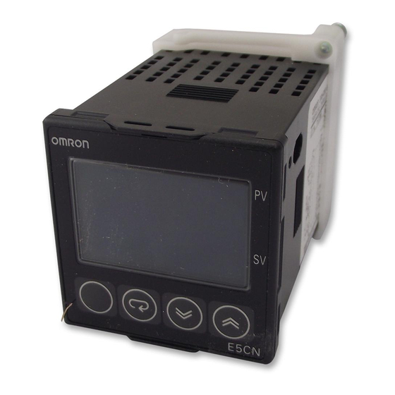
Basic-type Digital Temperature Controller
E5CN/E5CN-U
New 48 x 48-mm Basic Temperature
Controller with Enhanced Functions and
Performance. Improved Indication
Accuracy and Preventive Maintenance
Function.
Indication Accuracy
Thermocouple input: ±0.3% of PV (previous models: ±0.5%)
Pt input: ±0.2% of PV (previous models: ±0.5%)
Analog input: ±0.2% FS (previous models: ±0.5%)
New E5CN-U Models (Plug-in Models) with analog inputs and
current outputs.
A PV/SV-status display function can be set to alternate between
displaying the PV or SV and the status of the Temperature
Controller (auto/manual, RUN/STOP and alarms).
Preventive maintenance for relays using a Control Output ON/OFF Counter.
Main I/O Functions
Event Inputs
• None
• Two
Sensor Inputs
• Universal thermocouple/Pt inputs
(Models with temperature inputs)
• Analog current/voltage inputs
(Models with analog inputs)
Indication Accuracy
• Thermocouple input: 0.3% of PV
• Pt input: 0.2% of PV
• Analog input:
0.2% FS
Sampling Period and control update
• 250 ms
This data sheet is provided as a guideline for selecting products. Be sure to refer to the following user manuals for application precautions
and other information required for operation before attempting to use the product.
E5CN/E5AN/E5EN Digital Temperature Controllers User's Manual Basic Type (Cat. No. H156)
E5CN/E5AN/E5EN Digital Temperature Controllers Communications Manual Basic Type (Cat. No. H158)
(48 x 48 mm)
E5CN
2 Auxiliary Outputs
Control Output 2
• None
• Voltage output
(for driving SSR)
Control Output 1
• Relay output
• Voltage output (for driving SSR)
• Current output
• Long-life relay output (hybrid)
Basic-type Digital Temperature Controller
48
48-mm
E5CN
Refer to Safety Precautions on page 18.
4-digit, 11 segment display
2 line Display: PV and SV
• Auto/manual switching
• Temperature Controller status display
• Simple program function
• Control output ON/OFF count alarm
• PV change rate alarm
• Models optional with RS-485
communications
E5CN/E5CN-U
48
48-mm
E5CN-U
1
Advertisement
Table of Contents

Subscribe to Our Youtube Channel
Related Manuals for Omron E5CN


Summary of Contents for Omron E5CN
- Page 1 • Long-life relay output (hybrid) This data sheet is provided as a guideline for selecting products. Be sure to refer to the following user manuals for application precautions and other information required for operation before attempting to use the product.
- Page 2 Note: Not all combinations of function 1 and function 2 specifications are possible for Option Units (E53-CN@@N2). ✽1. Always connect an AC load to a long-life relay output. The output will not turn OFF if a DC load is connected because a triac is used for switching the circuit.
-
Page 3: Option Units
(current/voltage) Current output E5CN-C2MLD-500 Note: add power supply voltage to model to complete ordering code (ie. E5CN-R2MT-500 AC100-240 or E5CN-R2MTD-500 AC/DC24) Option Units One of the following Option Units can be mounted to provide the E5CN with additional functions. Functions... -
Page 4: Ordering Information Plug-In-Type Controllers
Relay output E5CN-R2TDU Thermocouple 24 VAC/VDC or resistance Voltage output (for driving SSR) E5CN-Q2TDU thermometer Current output E5CN-C2TDU Note: add power supply voltage to model to complete ordering code. (ie. E5CN-R2TU AC100-240 or E5CN-R2TDU AC/DC24) E5CN/E5CN-U Basic-type Digital Temperature Controller... - Page 5 Adapter Model Connectable models Model E58-CIFQ1 Terminal block models Y92F-45 Note: Use this Adapter when the panel has been previously prepared for the E5B@ (72x72 mm panel cut-out). Terminal Cover Connectable models Terminal block models Sockets (for Plug-in Models) Model...
-
Page 6: Specifications Ratings
Thermocouple: K, J, T, E, L, U, N, R, S, B, W, or PL II Platinum resistance thermometer: Pt100 or JPt100 Infrared temperature sensor: 10 to 70 C, 60 to 120 C, 115 to 165 C, or 140 to 260 C Sensor input... -
Page 7: Input Ranges
Shaded settings are the default settings. The applicable standards for the input types are as follows: K, J, T, E, N, R, S, B: JIS C 1602-1995, IEC 584-1 JPt100: JIS C 1604-1989, JIS C 1606-1989 L: Fe-CuNi, DIN 43710-1985... -
Page 8: Alarm Outputs
Auxiliary outputs are allocated for alarms. ON delays and OFF delays (0 to 999 s) can also be specified. Note: For models with heater burnout, SSR failure, and heater overcurrent detection, alarm 1 will be an OR output of the alarm selected from the following alarm types and the alarms for heater burnout, SSR failure, and heater overcurrent. - Page 9 The indication accuracy of B thermocouples in the 400 to 800 C range is 3 C max. The indication accuracy of the R and S thermocouples at a temperature of 200 C max. is 3 C 1 digit max. The indication accuracy of W thermocouples is 0.3 of PV or 3 C, whichever is greater, 1 digit max.
-
Page 10: Communications Specifications
Note: A driver must be installed in the personal computer. Refer to installation information in the operation manual for the alarm 1 function will turn ON if the heater current is lower than the Conversion Cable. set value (i.e., heater burnout detection current value). -
Page 11: External Connections
A voltage output (control output, for driving SSR) is not electrically insulated from the internal circuits. When using a grounding thermocouple, do not connect any of the control output terminals to ground. (If the control output terminals are connected to ground, errors will occur in the measured temperature values as a result of leakage current.) - Page 12 Nomenclature E5CN Temperature unit E5CN-U The front panel is the same for the E5CN and E5CN-U. No.1 display Operation indicators No. 2 display Up Key Level Key Mode Key Down Key Dimensions (Unit: mm) E5CN Panel Cutout Terminal Models Mounted Separately Group Mounted +1.0...
-
Page 13: Terminal Cover
Order the Waterproof Packing separately if it becomes lost or Note: The E53-COV10 damaged. cannot be used. The Waterproof Packing can be used to achieve an IP66 degree of protection. (Deterioration, shrinking, or hardening of the waterproof packing may occur depending on the operating environment. Therefore, periodic replacement is recommended to ensure the level of waterproofing specified in IP66. - Page 14 (Bottom View) 5 6 7 8 25.6 4.5 16.3 6.2 Note: 1. Using any other sockets will adversely affect accuracy. Use only the specified sockets. 2. A Protective Cover for finger protection (Y92A-48G) is also available. E5CN/E5CN-U Basic-type Digital Temperature Controller...
-
Page 15: Basic Type
Setting Levels Diagram This diagram shows all of the setting levels. To move to the advanced function setting level and calibration level, you must enter passwords. Some parameters are not displayed depending on the protect level setting and the conditions of use. -
Page 16: Manual Control Level
Press the O and M Keys for Press the O Key alt1 Alarm 1 Type at least 3 s. Press the O and M Keys for at least 1 s. less than 1 s. Communications wt-b Wait Band HS Alarm 2... -
Page 17: Advanced Function Setting Level
Press the O Key for at least 1 s. Advanced Function Setting Level Alarm 2 Type "PV/SP" Display alt2 spdp a1lt Alarm 1 Latch init HS Alarm Use Parameter Initialization Screen Selection Alarm 2 alh2 MV Display Selection HS Alarm Latch... -
Page 18: Safety Precautions
30 V r.m.s. and 42.4 V peak or 60 VDC. connected to the product. Malfunction may occur due to ✽2. A class 2 power supply is one tested and certified by UL as having noise in the cable. the current and voltage of the secondary output restricted to specific levels. -
Page 19: Precautions For Correct Use
3. Mount the product so that it is horizontally level. use RAM write mode when frequently overwriting data during 4. If the measurement accuracy is low, check to see if input shift has communications or other operations. been set correctly. -
Page 20: Precautions When Wiring
0.29 to 0.39 N·m. Mounting the Terminal Cover Make sure that the “UP” mark is facing up, and then attach the E53- COV17 Terminal Cover to the holes on the top and bottom of the Temperature Controller. - Page 21 E5CN/E5CN-U Basic-type Digital Temperature Controller...
-
Page 22: Warranty And Application Considerations
CONTRACT, WARRANTY, NEGLIGENCE, OR STRICT LIABILITY. In no event shall the responsibility of OMRON for any act exceed the individual price of the product on which liability is asserted. IN NO EVENT SHALL OMRON BE RESPONSIBLE FOR WARRANTY, REPAIR, OR OTHER CLAIMS REGARDING THE...
Need help?
Do you have a question about the E5CN and is the answer not in the manual?
Questions and answers