Table of Contents
Advertisement
Advertisement
Table of Contents

Related Manuals for Draytek Vigor 3200 Series


Summary of Contents for Draytek Vigor 3200 Series
- Page 2 Vigor3200 Series Multi-WAN Security Router User’s Guide Version: 1.5 Firmware Version: V3.3.7.2 (for future update, contact DrayTek) Date: 17/09/2012 Vigor3200 Series User’s Guide...
-
Page 3: Copyright Information
Web registration is preferred. You can register your Vigor router via Owner http://www.DrayTek.com. Firmware & Tools Due to the continuous evolution of DrayTek technology, all routers will be regularly Updates upgraded. Please consult the DrayTek web site for more information on newest firmware, tools and documents. -
Page 4: European Community Declarations
Product: Vigor3200 Series Router DrayTek Corp. declares that Vigor3200 Series of routers are in compliance with the following essential requirements and other relevant provisions of R&TTE Directive 1999/5/EEC. The product conforms to the requirements of Electro-Magnetic Compatibility (EMC) Directive 2004/108/EC by complying with the requirements set forth in EN55022/Class B and EN55024/Class B. - Page 5 Vigor3200 Series User’s Guide...
-
Page 6: Table Of Contents
Introduction ....................1 1.1 Web Configuration Buttons Explanation ................. 1 1.2 LED Indicators and Connectors ....................2 1.2.1 For Vigor3200 ........................2 1.2.2 For Vigor3200n ......................... 4 1.3 Hardware Installation ......................6 1.4 Printer Installation ........................7 Configuring Basic Settings ..............13 2.1 Accessing Web Page ...................... - Page 7 3.11.1 Creating an Account via Vigor Router ................80 3.11.2 Creating an Account via MyVigor Web Site..............83 3.12 How can I get the files from USB storage device connecting to Vigor router? ....87 3.13 VPN Trunk Load-Balance between Vigor 3200 and Other Vigor Router ......90 Advanced Web Configuration ..............101 4.1 WAN ............................
- Page 8 4.8.1 Sessions Limit....................... 201 4.8.2 Bandwidth Limit ......................203 4.8.3 Quality of Service......................205 4.9 Applications ......................... 214 4.9.1 Dynamic DNS ....................... 214 4.9.2 Schedule ........................216 4.9.3 RADIUS ........................220 4.9.4 LDAP / Active Directory ....................221 4.9.5 UPnP..........................223 4.9.6 IGMP..........................
- Page 9 4.15.2 TR-069 ........................313 4.15.3 Administrator Password....................314 4.15.4 User Password ......................315 4.15.5 Login Customization ....................317 4.15.6 Configuration Backup ....................319 4.15.7 Syslog/Mail Alert ......................321 4.15.8 Time and Date ......................324 4.15.9 Management....................... 325 4.15.10 Reboot System ......................326 4.15.11 Firmware Upgrade ....................
-
Page 11: Introduction
Vigor3200 Series, a broadband router, integrates IP layer QoS, NAT session/bandwidth management to help users control works well with large bandwidth. By adopting hardware-based VPN platform and hardware encryption of AES/DES/3DES, the router increases the performance of VPN greatly and offers several protocols (such as IPSec/PPTP/L2TP) with up to 32 VPN tunnels. -
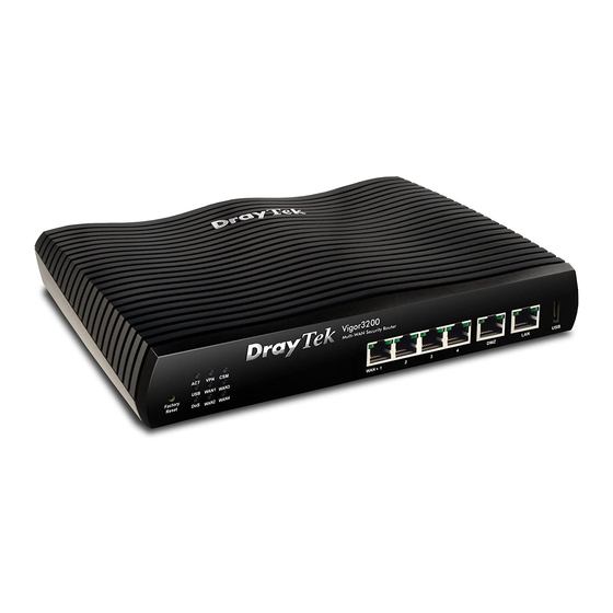
Page 12: Led Indicators And Connectors
Before you use the Vigor router, please get acquainted with the LED indicators and connectors first. Status Explanation ACT (Activity) Blinking The router is powered on and running normally. The router is powered off. USB device is connected and ready for use. Blinking The data is transmitting. - Page 13 Interface Description Factory Reset Restore the default settings. Usage: Turn on the router (ACT LED is blinking). Press the hole and keep for more than 5 seconds. When you see the ACT LED begins to blink rapidly than usual, release the button. Then the router will restart with the factory default configuration.
-
Page 14: For Vigor3200
Status Explanation ACT (Activity) Blinking The router is powered on and running normally. The router is powered off. USB device is connected and ready for use. Blinking The data is transmitting. WLAN Wireless access point is ready. Blinking Ethernet packets are transmitting over wireless LAN. - Page 15 Interface Description Wireless LAN Press "Wireless LAN ON/OFF/WPS" button once to wait for client device ON/OFF/WPS making network connection through WPS. Press "Wireless LAN ON/OFF/WPS" button twice to enable (WLAN LED on) or disable (WLAN LED off) wireless connection. Factory Reset Restore the default settings.
-
Page 16: Hardware Installation
Before starting to configure the router, you have to connect your devices correctly. Connect the cable Modem/DSL Modem/Media Converter to any WAN port of router with Ethernet cable (RJ-45). Connect one end of an Ethernet cable (RJ-45) to the LAN port of the router and the other end of the cable (RJ-45) into the Ethernet port on your computer. -
Page 17: Printer Installation
You can install a printer onto the router for sharing printing. All the PCs connected this router can print documents via the router. The example provided here is made based on Windows XP/2000. For Windows 98/SE/Vista, please visit www.DrayTek.com. Before using it, please follow the steps below to configure settings for connected computers (or wireless clients). - Page 18 Open File->Add Printer. A welcome dialog will appear. Please click Next. Click Local printer attached to this computer and click Next. In this dialog, choose Create a new port Type of port and use the drop down list to select Standard TCP/IP Port. Click Next. Vigor3200 Series User’s Guide...
- Page 19 In the following dialog, type 192.168.1.1 (router’s LAN IP) in the field of Printer Name or IP Address and type IP_192.168.1.1 as the port name. Then, click Next. Click Standard and choose Generic Network Card. Then, in the following dialog, click Finish. Vigor3200 Series User’s Guide...
- Page 20 Now, your system will ask you to choose right name of the printer that you installed onto the router. Such step can make correct driver loaded onto your PC. When you finish the selection, click Next. 10. For the final stage, you need to go back to Control Panel-> Printers and edit the property of the new printer you have added.
- Page 21 If you do not know whether your printer is supported or not, please visit www.DrayTek.com to find out the printer list. Open Support >FAQ; find out the link of Printer Server and click it; then choose the What types of printers are compatible with Vigor router?.
- Page 22 This page is left blank. Vigor3200 Series User’s Guide...
-
Page 23: Configuring Basic Settings
For using the router properly, it is necessary for you to change the password of web configuration for security and adjust primary basic settings. This chapter explains how to setup a password for accessing into the web configurator of Vigor router and how to adjust settings for accessing Internet successfully. Make sure your PC connects to the router correctly. -
Page 24: Changing Password
No matter user mode operation or admin mode operation, please change the password for the original security of the router. Open a web browser on your PC and type http://192.168.1.1. A pop-up window will open to ask for username and password. Please type “admin/admin”... -
Page 25: Quick Start Wizard
Enter the login password on the field of Old Password. Type New Password and confirm the password. Then click OK to continue. Now, the password has been changed. Next time, use the new password to access the Web Configurator for this router. Notice: Quick Start Wizard for user mode operation is the same as for admin mode operation. -
Page 26: For Wan1 - Wan4
Note: There are five WAN selections available for you to choose. In which, WAN5 is selected for 3G USB modem connection. Refer to the following for detailed information. – – Choose WAN1/WAN2/WAN3/WAN4 and click Next. On the next page as shown below, please select the appropriate Internet access type according to the information from your ISP. - Page 27 Click PPPoE as the Internet Access Type. Then click Next to open the following page. Available settings are explained as follows: Item Description User Name Assign a specific valid user name provided by the ISP. Password Assign a valid password provided by the ISP. Confirm Password Retype the password.
- Page 28 Click Finish. A page of Quick Start Wizard Setup OK!!! will appear. Then, the system status of this protocol will be shown. Now, you can enjoy surfing on the Internet. Vigor3200 Series User’s Guide...
- Page 29 Choose WAN1/WAN2/WAN3/WAN4 as the WAN Interface and click the Next button. The following page will be open for you to specify Internet Access Type. Click PPTP/L2TP as the Internet Access Type. Then click Next to continue. Available settings are explained as follows: Item Description User Name...
- Page 30 WAN IP Obtain an IP address automatically – the router will get an Configuration IP address automatically from DHCP server. Specify an IP address – you have to type relational settings manually. IP Address - Type the IP address. Subnet Mask –Type the subnet mask. Gateway –...
- Page 31 1. Choose WAN1/WAN2/WAN3/WAN4 as the WAN Interface and click the Next button. The following page will be open for you to specify Internet Access Type. 2. Click Static IP as the protocol. Type in all the information that your ISP provides for this protocol.
- Page 32 Back Click it to return to previous setting page. Next Click it to get into the next setting page. Cancel Click it to give up the quick start wizard. 3. After finishing the settings in this page, click Next to see the following page. 4.
- Page 33 1. Choose WAN1/WAN2/WAN3/WAN4 as the WAN Interface and click the Next button. The following page will be open for you to specify Internet Access Type. 2. Click DHCP as the protocol. Type in all the information that your ISP provides for this protocol.
-
Page 34: For Wan5
Cancel Click it to give up the quick start wizard. 3. After finishing the settings in this page, click Next to see the following page. 4. Click Finish. A page of Quick Start Wizard Setup OK!!! will appear. Then, the system status of this protocol will be shown. - Page 35 Then, click Next to continue. Click Finish. A page of Quick Start Wizard Setup OK!!! will appear. Then, the system status of this protocol will be shown. Now, you can enjoy surfing on the Internet. Vigor3200 Series User’s Guide...
-
Page 36: Service Activation Wizard
Service Activation Wizard is a tool which allows you to use trial version or update the license of WCF directly without accessing into the server (MyVigor) located on http://myvigor.draytek.com. For using Web Content Filter Profile, please refer to later section Web Content Filter Profile for detailed information. - Page 37 In the following page, you can activate the Web content filter service at the same time or individually. When you finish the selection, please click Next. Setting confirmation page will be displayed as follows, please click Next. Wait for a moment till the following page appears. When such page appears, you can enable or disable these services for your necessity.
- Page 38 Now, the web page will display the service that you have activated according to your selection(s). The valid time for the free trial of these services is one month. Later, if you need to extend the license valid time, you can also use the Service Activation Wizard again to reach your goal by clicking the radio button of Formal edition with license key and clicking Next.
-
Page 39: Online Status
The online status shows the system status, WAN status, and other status related to this router within one page. If you select PPPoE as the protocol, you will find out a link of Dial PPPoE or Drop PPPoE in the Online Status web page. Detailed explanation is shown below: Item Description... -
Page 40: Saving Configuration
Settings Saved means your settings are saved once you click Finish or OK button. When you click the menu item under Support Area, you will be guided to visit www.draytek.com and open the corresponding pages directly. Vigor3200 Series User’s Guide... - Page 41 Click Support Area>>Application Note, the following web page will be displayed. Click Support Area>>FAQ, the following web page will be displayed. Click Support Area>>Product Registration, the following web page will be displayed. Vigor3200 Series User’s Guide...
-
Page 42: Registering Vigor Router
You have finished the configuration of Quick Start Wizard and you can surf the Internet at any time. Now it is the time to register your Vigor router to MyVigor website for getting more service. Please follow the steps below to finish the router registration. Please login the web configuration interface of Vigor router by typing “admin/admin”... - Page 43 A Login page will be shown on the screen. Please type the account and password that you created previously. And click Login. The following page will be displayed after you logging in MyVigor. From this page, please click Add or Product Registration. Note: Below the field of Your Device List, all the Vigor routers that you have registered to MyVigor website will be displayed in sequence.
- Page 44 When the following page appears, please type in Nickname (for the router) and choose the right registration date from the popup calendar (it appears when you click on the box of Registration Date). After adding the basic information for the router, please click Submit.
-
Page 45: Tutorials And Applications
There is no need to pre-configure user profile for each user on Vigor router anymore. We only need to configure the Groups DN, then the Vigor router (e.g., Vigor 3200 series) can pass the authentication to LDAP server with the pre-defined Group path. - Page 46 Create LDAP server profiles. Click the Active Directory /LDAP tab to open the profile web page and click any one of the index number link. If we have two groups “RD1” and “SHRD” on LDAP server, we can configure two LDAP server profiles with different Group Distinguished Name.
- Page 47 Then open User Management>>User Profile to create the user profile that will authenticate with LDAP server. After above configurations, users belong to either “rd1” or “shrd” group can access Internet after inputting their credentials on LDAP server. Vigor3200 Series User’s Guide...
-
Page 48: How To Implement The Ad/Ldap Authentication For Ssl Application
Below shows the configuration steps: Access into the web configurator of the Vigor router. Open Applications>>Active Directory /LDAP to get the following page for configuring LDAP related settings. Click the General Setup tab and enable the AD/LDAP service. There are three types of bind type supported: Simple Mode –... - Page 49 Click the Active Directory /LDAP tab to open the profile web page. Click any one of the index number link to configure the proper Base Distinguished Name and Group Distinguished Name. Suppose that there are several departments in your company, e.g., RD1 and RD2. Here, create a profile for RD1 first.
- Page 50 Press the button on this page to keep searching its sub-tree. In addition, means this item is an organization; means this item is an account. Press certain item, its Base Distinguished Name (BDN) will be shown automatically in the AD/LDAP Distinguished Name field box. Then, press OK to save the profile and return to the previous page.
- Page 51 AD/LDAP configuration. However, you may need, sometimes, to separate certain accounts’ authority with it. For example, the Base Distinguished Name (BDN) is “ou=people,dc=ms,dc=draytek,dc=com”. There is a lot of accounts information. But, only several of them you may prefer to grant the authority of VPN dial-up.
- Page 52 Setup two applications profiles (named PC1 and PC2) for SSL VPN. 10. Setup two SSL Web Proxy Servers profiles (named google and baidu) for SSL VPN. Go to SSL VPN >>User Group to setup two separate groups (named with g1 and g2) with different authorities and different authentication methods.
- Page 53 Set the user group profile (named g2) for RD2 department: Vigor3200 Series User’s Guide...
- Page 54 Once you’ve finished the configuration on Vigor router, try to login SSL portal with https://<IPAddress>/ . Please type in the user name and password, and select the group that the account belongs to (In this case, the username is Caesar and the group it belongs to is g1). You may also leave this Group option blank.
- Page 55 Vigor3200 Series User’s Guide...
-
Page 56: How To Configure Multi-Subnet
By identifying the tagged message, Vigor3200 can divide the LAN Port into several VLAN groups. Such LAN port with tagged information will accept the packets only with VLAN ID number. For example, Vigor3200 can divide the internal departments of a company into four different groups by using VigorSwitch G2240. - Page 57 Configuration for Vigor3200 In the page of LAN >> VLAN Configuration, check the box of Enable to enable the function of VLAN Configuration. Untag VLAN0 and set LAN4 as the Subnet. To activate the function of VLAN Tag for VLAN1 setting, check the box of Enable and type the value (10) for VID setting.
- Page 58 After finishing the above configuration, the equipment connecting to Vigor3200 LAN Port can get the corresponding IP address of the network segment. The equipment connecting to Vigor3200 LAN Port (LAN1) can get the IP address of 192.168.1.0/24. The equipment connecting to Vigor3200 LAN Port (LAN2) can get the IP address of 192.168.2.0/24.
- Page 59 To make any two of VLAN groups linked with each other, just check the boxes of the ones in the field of Inter-LAN Routing in the page of LAN >> General Setup. Refer to the following figure. LAN2 and LAN3 are linked. Configuration for VigorSwitch G2240 Open Vlan>>Tag-based Group.
- Page 60 After finishing the above configuration, the equipment connecting to VigorSwitch Port 15, 16, 17 and 18 can get the corresponding IP address(es) of the network segment. The equipment connecting to VigorSwitch Port 15 can get the IP address of 192.168.1.0/24 The equipment connecting to VigorSwitch Port 16 can get the IP address of 192.168.2.0/24 The equipment connecting to VigorSwitch Port 17 can get the IP address of...
-
Page 61: How To Customize Your Login Page
Login page can be customized to fit the request of the administrator. Open User Management>>General Setup. Set User-Based as the Mode and click OK to save teh settings. Open User Management>>User Profile to create a new user profle. Click any link (e.g., #3) to access into the following page. Type a User Name and a Password. - Page 62 Open System Maintenance>>Login Customization. Check the box to enable this function. Type a brief description (e.g., Just for Carrie) in the field of Login Description which will be shown on the heading of the login dialog. Next, click OK. Note that do not type URL redirect link in Bulletin box. Open a new tab in the same browser (for IE 7.0/FireFox and above) or open a new web browser.
-
Page 63: Create A Lan-To-Lan Connection Between Remote Office And Headquarter
The most common case is that you may want to connect to network securely, such as the remote branch office and headquarter. According to the network structure as shown in the below illustration, you may follow the steps to create a LAN-to-LAN profile. These two networks (LANs) should NOT have the same network address. - Page 64 Go to LAN-to-LAN. Click on one index number to edit a profile. Set Common Settings as shown below. You should enable both of VPN connections because any one of the parties may start the VPN connection. Vigor3200 Series User’s Guide...
- Page 65 Set Dial-Out Settings as shown below to dial to connect to Router B aggressively with the selected Dial-Out method. If an IPSec-based service is selected, you should further specify the remote peer IP Address, IKE Authentication Method and IPSec Security Method for this Dial-Out connection.
- Page 66 Set Dial-In settings to as shown below to allow Router B dial-in to build VPN connection. If an IPSec-based service is selected, you may further specify the remote peer IP Address, IKE Authentication Method and IPSec Security Method for this Dial-In connection.
- Page 67 At last, set the remote network IP/subnet in TCP/IP Network Settings so that Router A can direct the packets destined to the remote network to Router B via the VPN connection. Settings in Router B in the remote office: Go to VPN and Remote Access and select Remote Access Control to enable the necessary VPN service and click OK.
- Page 68 Go to LAN-to-LAN. Click on one index number to edit a profile. Set Common Settings as shown below. You should enable both of VPN connections because any one of the parties may start the VPN connection. Set Dial-Out Settings as shown below to dial to connect to Router B aggressively with the selected Dial-Out method.
- Page 69 If a PPP-based service is selected, you should further specify the remote peer IP Address, Username, Password, PPP Authentication and VJ Compression for this Dial-Out connection. Vigor3200 Series User’s Guide...
- Page 70 Set Dial-In settings to as shown below to allow Router A dial-in to build VPN connection. If an IPSec-based service is selected, you may further specify the remote peer IP Address, IKE Authentication Method and IPSec Security Method for this Dial-In connection.
- Page 71 At last, set the remote network IP/subnet in TCP/IP Network Settings so that Router B can direct the packets destined to the remote network to Router A via the VPN connection. Vigor3200 Series User’s Guide...
-
Page 72: Create A Remote Dial-In User Connection Between The Teleworker And Headquarter
The other common case is that you, as a teleworker, may want to connect to the enterprise network securely. According to the network structure as shown in the below illustration, you may follow the steps to create a Remote User Profile and install Smart VPN Client on the remote host. - Page 73 Go to Remote Dial-In User. Click on one index number to edit a profile. Set Dial-In settings to as shown below to allow the remote user dial-in to build VPN connection. If an IPSec-based service is selected, you may further specify the remote peer IP Address, IKE Authentication Method and IPSec Security Method for this Dial-In connection.
- Page 74 For Win2000/XP, please use "Network and Dial-up connections" or “Smart VPN Client”, complimentary software to help you create PPTP, L2TP, and L2TP over IPSec tunnel. You can find it in CD-ROM in the package or go to www.DrayTek.com download center. Install as instructed.
- Page 75 In Step 2. Connect to VPN Server, click Insert button to add a new entry. If an IPSec-based service is selected as shown below, You may further specify the method you use to get IP, the security method, and authentication method. If the Pre-Shared Key is selected, it should be consistent with the one set in VPN router.
- Page 76 then forwarded to Internet. This will make the remote host seem to be working in the enterprise network. Click Connect button to build connection. When the connection is successful, you will find a green light on the right down corner. Vigor3200 Series User’s Guide...
-
Page 77: Qos Setting Example
Assume a teleworker sometimes works at home and takes care of children. When working time, he would use Vigor router at home to connect to the server in the headquarter office downtown via either HTTPS or VPN to check email and access internal database. Meanwhile, children may chat on Skype in other room. - Page 78 Return to previous page. Enter the Name of Index Class 1 by clicking Edit link. Type the name “E-mail” for Class 1. For this index, the user will set reserved bandwidth (e.g., 25%) for E-mail using protocol POP3 and SMTP. Return to previous page.
- Page 79 Click Setup link for one of the WAN interface. Check Enable UDP Bandwidth Control on the bottom to prevent enormous UDP traffic of influent other application. Click OK. Vigor3200 Series User’s Guide...
- Page 80 If the worker has connected to the headquarter using host to host VPN tunnel. (Please refer to Chapter 3 VPN for detail instruction), he may set up an index for it. Enter the Class Name of Index 3. In this index, he will set reserved bandwidth for 1 VPN tunnel. 10.
-
Page 81: Upgrade Firmware For Your Router
Before upgrading your router firmware, you need to install the Router Tools. The Firmware Upgrade Utility is included in the tools. 1. Go to www.DrayTek.com. 2. Access into Support >> Downloads. Please find out Firmware menu and click it. Search the model you have and click on it to download the newly update firmware for your router. - Page 82 5. Double click on the icon of router tool. The setup wizard will appear. 6. Follow the onscreen instructions to install the tool. Finally, click Finish to end the installation. 7. From the Start menu, open Programs and choose Router Tools XXX >> Firmware Upgrade Utility.
- Page 83 The web page also can guide you to upgrade firmware. Note that this example is running over Windows OS (Operating System). Download the newest firmware from DrayTek's web site or FTP site. The DrayTek web site is www.DrayTek.com (or local DrayTek's web site) and FTP site is ftp.DrayTek.com.
-
Page 84: Request A Certificate From A Ca Server On Windows Ca Server
Go to Certificate Management and choose Local Certificate. Vigor3200 Series User’s Guide... - Page 85 You can click GENERATE button to start to edit a certificate request. Enter the information in the certificate request. Copy and save the X509 Local Certificate Requet as a text file and save it for later use. Connect to CA server via web browser. Follow the instruction to submit the request. Below we take a Windows 2000 CA server for example.
- Page 86 Select Advanced request. Select Submit a certificate request a base64 encoded PKCS #10 file or a renewal request using a base64 encoded PKCS #7 file Import the X509 Local Certificate Requet text file. Select Router (Offline request) or IPSec (Offline request) below. Then you have done the request and the server now issues you a certificate.
- Page 87 you will find the below window showing “------BEGINE CERTIFICATE------..” You may review the detail information of the certificate by clicking View button. Vigor3200 Series User’s Guide...
-
Page 88: Request A Ca Certificate And Set As Trusted On Windows Ca Server
Use web browser connecting to the CA server that you would like to retrieve its CA certificate. Click Retrive the CA certificate or certificate recoring list. Vigor3200 Series User’s Guide... - Page 89 In Choose file to download, click CA Certificate Current and Base 64 encoded, and Download CA certificate to save the .cer. file. Back to Vigor router, go to Trusted CA Certificate. Click IMPORT button and browse the file to import the certificate (.cer file) into Vigor router. When finished, click refresh and you will find the below illustration.
-
Page 90: Creating An Account For Myvigor
The website of MyVigor (a server located on http://myvigor.draytek.com) provides several useful services (such as Anti-Spam, Web Content Filter, Anti-Intrusion, and etc.) to filter the web pages for protecting your system. To access into MyVigor for getting more information, please create an account for MyVigor first. - Page 91 4. Check to confirm that you accept the Agreement and click Accept. 5. Type your personal information in this page and then click Continue. 6. Choose proper selection for your computer and click Continue. Vigor3200 Series User’s Guide...
- Page 92 New Account Confirmation 8. Check to see the confirmation email with the title of Letter from myvigor.draytek.com. 9. Click the Activate my Account link to enable the account that you created. The following screen will be shown to verify the register process is finished. Please click Login.
-
Page 93: Creating An Account Via Myvigor Web Site
11. Now, click Login. Your account has been activated. You can access into MyVigor server to activate the service (e.g., WCF) that you want. 1. Access into http://myvigor.draytek.com. Find the line of Not registered yet?. Then, click the link Click here! to access into next page. - Page 94 2. Check to confirm that you accept the Agreement and click Accept. 3. Type your personal information in this page and then click Continue. 4. Choose proper selection for your computer and click Continue. Vigor3200 Series User’s Guide...
- Page 95 New Account Confirmation 6. Check to see the confirmation email with the title of Letter from myvigor.draytek.com. 7. Click the Activate my Account link to enable the account that you created. The following screen will be shown to verify the register process is finished. Please click Login.
- Page 96 8. When you see the following page, please type in the account and password (that you just created) in the fields of UserName and Password. Then type the code in the box of Auth Code according to the value displayed on the right side of it. Now, click Login.
-
Page 97: How Can I Get The Files From Usb Storage Device Connecting To Vigor Router
Files on USB storage device can be reviewed by opening USB Applicaiton>>File Explorer. If it is necessary for you to delete, copy files on the device or write, paste files to the devcie, it must be done through SAMBA server or FTP server. Samba service is based on the original USB FTP service. - Page 98 Setup a user account for the FTP service by using USB Application >>USB User Management. Click Enable to enable FTP/Samba User account. Here we add a new account "user1" and assign authorities “Read”, “Write” and “List” to it. Click OK to save the configuration. Make sure the FTP service is running properly.
- Page 99 When the following screen appears, it means the FTP service is running properly. Return to USB Application >> USB Disk Status. The information for FTP server will be shown as below. Now, users in LAN of Vigor3200 can access into the USB storage device by typing ftp://192.168.1.1 on any browser.
-
Page 100: Vpn Trunk Load-Balance Between Vigor 3200 And Other Vigor Router
This section will discuss how to build VPN Trunk with load-balance between Vigor3200 and other router (e.g., Vigor3300). The purpose is to setup a VPN trunk between Vigor3200 (192.168.1.0/24) and Vigor3300 (192.168.33.0/24). At present, Vigor3200 just supports one VPN trunk group with two members for the same VPN network pair. - Page 101 Settings for Vigor 3200: 1. Open VPN and Remote Access>>>LAN to LAN. Choose Index number 1 for configuring a VPN LAN to LAN profile. 2. In the following page, please configure the settings as the following figure. Vigor3200 Series User’s Guide...
- Page 102 3. Click OK to save the configuration and return to previous page. Choose Index number 2 for configuring another VPN LAN to LAN profile. 4. In this page, please configure the settings as the following figure. Vigor3200 Series User’s Guide...
- Page 103 5. Click OK to save the configuration. 6. Open VPN and Remote Access>>VPN TRUNK Management. Add these VPN profiles to the VPN Trunk and set Load Balance as the Attribute Mode. 7. Click Advanced for specifying Load Balance Algorithm. Vigor3200 Series User’s Guide...
- Page 104 8. When the VPN trunk is successfully connected, you may check the connection status by viewing the page of VPN and Remote Access>>Connection Management. Transferred packets (Tx Pkts) will keep increasing through both tunnels when outgoing packets sent to the remote VPN network. Settings for Vigor3300: 1.
- Page 105 2. In this page, please configure the settings as the following figure. 3. Click Apply to save the configuration and return to previous page. Choose Index 2 for configuring another VPN Trunk policy. 4. In this page, please configure the settings as the following figure. Vigor3200 Series User’s Guide...
- Page 106 5. Click Apply to save the configuration. 6. Open VPN>>VPN Trunk>>Group Table to group these two VPN policies. 7. Choose Index 1 and click Edit. Add these two VPN profiles (wan1 and wan2) to a VPN Trunk. Now, one-pair VPN trunk between Vigor3200 (192.168.1.0/24) and Vigor3300 (192.168.33.0/24) has be established.
- Page 107 Vigor3200 as VPN client (dial out site) LAN: 192.168.1.0/24 WAN 1 IP: 202.211.110.30 (My GRE IP, 10.0.0.1, Peer GRE IP, 10.0.0.2) WAN 2 IP: 202.211.120.30 (My GRE IP, 10.0.0.3, Peer GRE IP, 10.0.0.4) WAN 3 IP: 202.211.130.30 (My GRE IP, 10.0.0.5, Peer GRE IP, 10.0.0.6) WAN 4 IP: 202.211.140.30 (My GRE IP, 10.0.0.7, Peer GRE IP, 10.0.0.8) Vigor3300 as VPN server (dial in site), LAN1: 192.168.33.0/24...
- Page 108 3. Open VPN and Remote Access>>VPN TRUNK Management. Add these VPN profiles to the VPN Trunk and set Load Balance as the Attribute Mode. Setting configuration is the same as Scenario 1. Profile 1 and Profile 2 are one pair; Profile 3 and Profile 4 are the other pair.
- Page 109 Settings for Vigor3300: 1. Open Advanced>>LAN VLAN. Choose the tab of 802.1Q VLAN. Configure the settings as the following figure. 2. Next, open Network>>LAN. Set two LAN subnet: LAN1 192.168.33.0/24 and LAN2 192.168.10.0/24. 3. Click Apply. 4. Open VPN>>IPSec>>VPN Trunk>>Policy Table to create VPN Trunk policy. The way Vigor3200 Series User’s Guide...
- Page 110 to configure the setting is the same as Scenario 1. 5. Open VPN>>VPN Trunk>>Group Table to group these VPN policies. Group two VPN policies as the following figure and then click Apply. The way to configure the setting is the same as Scenario 1. Now, two-pair VPN trunk between Vigor3200 (192.168.1.0/24) and Vigor3300 (192.168.33.0/24) has be established.
-
Page 111: Advanced Web Configuration
This chapter will guide users to execute advanced (full) configuration through admin mode operation. As for other examples of application, please refer to chapter 5. Open a web browser on your PC and type http://192.168.1.1. The window will ask for typing username and password. - Page 112 has reserved certain addresses that will never be registered publicly. These are known as private IP addresses, and are listed in the following ranges: From 10.0.0.0 to 10.255.255.255 From 172.16.0.0 to 172.31.255.255 From 192.168.0.0 to 192.168.255.255 As the router plays a role to manage and further protect its LAN, it interconnects groups of host PCs.
-
Page 113: General Setup
Besides, 3G USB Modem also can be used as backup device. Therefore, when other Ethernet WAN ports are not available, the router will use 3.5G for supporting automatically. The supported 3G USB Modem will be listed on DrayTek web site. Please visit www.DrayTek.com for more detailed information. - Page 114 Index Click the WAN interface link under Index to access into the WAN configuration page. Enable V means such WAN interface is enabled and ready to be used. Physical Mode / Type Display the physical mode and physical type of such WAN interface.
- Page 115 Item Description Enable Choose Yes to invoke the settings for this WAN interface. Choose No to disable the settings for this WAN interface. Display Name Type the description for such WAN interface. Display the physical mode of such WAN interface. Physical Mode Physical type You can change the physical type for WAN2 or choose Auto...
- Page 116 When any WAN disconnect – WAN1 will be activated when any WAN interface disconnects. When all WAN disconnect – WAN1 will be activated when all the WAN interfaces disconnect. After finished the above settings, click OK to save the settings. To use 3G network connection through 3G USB Modem, please configure WAN5 interface.
-
Page 117: Internet Access
Active Mode Determine the WAN interface will be active for always (Always On) or be treated as a backup WAN interface (Backup). Backup Type - Determine the role of such WAN interface. It will be changed according to the Active Mode specified. If you choose Always On as Active Mode, such interface will be used for access into Internet all the time. - Page 118 Each item is explained as follows: Item Description Index Display the WAN interface. It shows the name of the Display Name WAN1/WAN2/WAN3/WAN4/WAN5 that entered in general setup. Physical Mode It shows the physical connection for WAN1-WAN4 (Ethernet) /WAN5 (3G USB Modem) according to the real network connection.
- Page 119 To choose PPPoE as the accessing protocol of the internet, please select PPPoE from the Internet Access menu. The following web page will be shown. Available settings are explained as follows: Item Description PPPoE Client Mode Click Enable for activating this function. If you click Disable, this function will be closed and all the settings that you adjusted in this page will be invalid.
- Page 120 Item Description have to type IP address in this field for pinging. TTL (Time to Live) – Displays value for your reference. TTL value is set by telnet command. It means Max Transmit Unit for packet. The default setting is 1442.
- Page 121 Item Description Fixed IP – Click Yes to use this function and type in a fixed IP address in the box of Fixed IP Address. Default MAC Address – You can use Default MAC Address or specify another MAC address by typing on the boxes of MAC Address for the router.
- Page 122 Available settings are explained as follows: Item Description Static or Dynamic IP Click Enable for activating this function. If you click Disable, this function will be closed and all the settings that you adjusted in this page will be invalid. Keep WAN Connection Normally, this function is designed for Dynamic IP environments because some ISPs will drop connections if...
- Page 123 Item Description It means Max Transmit Unit for packet. The default setting is 1442. RIP Protocol Routing Information Protocol is abbreviated as RIP(RFC1058) specifying how routers exchange routing tables information. Click Enable RIP for activating this function. Bridge Mode If you check this box to invoke the function, the router will work as a bridge.
- Page 124 Item Description MAC address for the router. Specify a MAC Address: Some Cable service providers specify a specific MAC address for access authentication. In such cases you need to click the Specify a MAC Address and enter the MAC address in the MAC Address field. DNS Server IP Address - Type in the primary IP address for the router if you want to use Static IP mode.
- Page 125 To use PPTP/L2TP as the accessing protocol of the internet, please choose PPTP/L2TP from Internet Access menu. The following web page will be shown. Available settings are explained as follows: Item Description PPTP/L2TP Client Enable PPTP- Click this radio button to enable a PPTP client Mode to establish a tunnel to a DSL modem on the WAN interface.
- Page 126 Item Description after passing through the time without any action. IP Address Assignment Fixed IP - Usually ISP dynamically assigns IP address to you Method(IPCP) each time you connect to it and request. In some case, your ISP provides service to always assign you the same IP address whenever you request.
- Page 127 After finishing all the settings here, please click OK to activate them. To use PPP (for 3G USB Modem) as the accessing protocol of the internet, please choose Internet Access from WAN menu. Then, select PPP mode for WAN5. The following web page will be shown.
- Page 128 Item Description ISP. PPP Username Type the PPP username (optional). PPP Password Type the PPP password (optional). Index (1-15) in Schedule Set the PCs on LAN to work at certain time interval only. You Setup can type in four sets of time schedule for your request. All the schedules can be set previously in Application >>Schedule web page and you can use the number that you have set in that web page.
-
Page 129: Load-Balance Policy
This router supports the function of load balancing. It can assign traffic with protocol type, IP address for specific host, a subnet of hosts, and port range to be allocated in WAN interface. The user can assign traffic category and force it to go to dedicate network interface based on the following web page setup. - Page 130 Click any Index number link to access into the following page for configuring load-balance policy. Each item is explained as follows: Item Description Enable Check this box to enable this policy. Protocol Use the drop-down menu to choose a proper protocol for the WAN interface.
-
Page 131: Lan
passed through the WAN interface. After finishing all the settings here, please click OK to activate them. Local Area Network (LAN) is a group of subnets regulated and ruled by router. The design of network structure is related to what type of public IP addresses coming from your ISP. The most generic function of Vigor router is NAT. - Page 132 In some special case, you may have a public IP subnet from your ISP such as 220.135.240.0/24. This means that you can set up a public subnet or call second subnet that each host is equipped with a public IP address. As a part of the public subnet, the Vigor router will serve for IP routing to help hosts in the public subnet to communicate with other public hosts or servers outside.
-
Page 133: General Setup
You can group local hosts by physical port and create up to 4 virtual LANs. To manage the communication between different groups, please set up rules in Virtual LAN (VLAN) function and the rate of each. This page provides you the general settings for LAN. Vigor3200 series provides four LANs, one DMZ and one IP Routed Subnet. - Page 134 Each item is explained as follows: Item Description General Setup----- Allow to configure settings for each subnet respectively. Index - Display all of the LAN items, DMZ and IP Routed Subnet. Status- Check the box to enable such LAN configuration. Basically, LAN1 status is enabled in default.
- Page 135 Inter-LAN Routing LAN 1 ~ LAN 4, DMZ PORT - Check the box to make the routing among LANs. After finishing all the settings here, please click OK to save the configuration. To configure LAN 1 ~ LAN 4, DMZ or IP Routed Subnet, simply click Details Page to open the settings page.
- Page 136 Item Description in the LAN. Disable Server - Let you manually assign IP address to every host in the LAN. Relay Agent - Specify which subnet that DHCP server is located the relay agent should redirect the DHCP request to. Start IP Address - Enter a value of the IP address pool for the DHCP server to start with when issuing IP addresses.
- Page 137 Item Description external DNS server by establishing a WAN (e.g. DSL/Cable) connection. After finishing all the settings here, please click OK to save the configuration. With the multi-subnet feature offered by Vigor router, LAN2 ~ LAN4 are used for different subnets.
- Page 138 DHCP Server DHCP stands for Dynamic Host Configuration Protocol. The Configuration router by factory default acts a DHCP server for your network so it automatically dispatch related IP settings to any local user configured as a DHCP client. It is highly recommended that you leave the router enabled as a DHCP server if you do not have a DHCP server for your network.
- Page 139 For NAT Usage - Click this item to invoke NAT usage. For Routing Usage - Click this item to invoke Routing usage. IP Address - Type in private IP address for connecting to a local private network (Default: 192.168.9.1). Subnet Mask - Type in an address code that determines the size of the network.
- Page 140 Vigor router can serve as a DHCP server to route the request coming from LAN PC. Available settings are explained as follows: Item Description Network Configuration Enable/Disable - Click Enable to enable such configuration; click Disable to disable such configuration. IP Address - Type in IP address for connecting to a local private network (Default: 192.168.0.1).
-
Page 141: Static Route
IP Pool Counts - Enter the maximum number of PCs that you want the DHCP server to assign IP addresses to. The default is 10. Use LAN Port – Specify an IP for IP Route Subnet. If it is enabled, DHCP server will assign IP address automatically for the clients coming from P1 and/or P2. - Page 142 Here is an example of setting Static Route in Main Router so that user A and B locating in different subnet can talk to each other via the router. Assuming the Internet access has been configured and the router works properly: use the Main Router to surf the Internet.
- Page 143 Click the LAN>> Static Route and click on the Index number 1. Please add a static route as shown below, which regulates all packets destined to 192.168.10.0 will be forwarded to 192.168.1.2. Click OK. Return to Static Route Setup page. Click on another Index Number to add another static route as show below, which regulates all packets destined to 211.100.88.0 will be forwarded to 192.168.1.3.
-
Page 144: Vlan
Virtual LAN function provides you a very convenient way to manage subnets by grouping them. Go to LAN page and select VLAN. The following page will appear. Click Enable to invoke VLAN function. Available settings are explained as follows: Item Description VLAN Tag Enable –... -
Page 145: Bind Ip To Mac
Subnet Choose one of them to make the selected VLAN mapping to the specified subnet only. For example, LAN1 is specified for VLAN0. It means that PCs grouped under VLAN0 can get the IP address (es) that specified by the subnet. After finishing all the settings here, please click OK to save the configuration. -
Page 146: Lan Port Mirror
Strict Bind Click this radio button to block the connection of the IP/MAC which is not listed in IP Bind List. ARP Table This table is the LAN ARP table of this router. The information for IP and MAC will be displayed in this field. Each pair of IP and MAC address listed in ARP table can be selected and added to IP Bind List by clicking Add below Select All... - Page 147 Available settings are explained as follows: Item Description Port Mirror Check Enable to activate this function. Or, check Disable to close this function. Mirror Port Select a port to view traffic sent from mirrored ports. At present, only WAN4 will be treated as mirror port. When Port Mirror is enabled, the Mirror Port (WAN4) will be disabled.
-
Page 148: Nat
Usually, the router serves as an NAT (Network Address Translation) router. NAT is a mechanism that one or more private IP addresses can be mapped into a single public one. Public IP address is usually assigned by your ISP, for which you may get charged. Private IP addresses are recognized only among internal hosts. -
Page 149: Port Redirection
Port Redirection is usually set up for server related service inside the local network (LAN), such as web servers, FTP servers, E-mail servers etc. Most of the case, you need a public IP address for each server and this public IP address/domain name are recognized by all users. Since the server is actually located inside the LAN, the network well protected by NAT of the router, and identified by its private IP address/port, the goal of Port Redirection function is to forward all access request with public IP address from external users to the mapping private IP... - Page 150 Each item is explained as follows: Item Description Display the number of the profile. Index Service Name Display the description of the specific network service. Protocol Display the transport layer protocol (TCP or UDP). Public Port Display the port number which will be redirected to the specified Private IP and Port of the internal host.
- Page 151 Private IP Specify the private IP address of the internal host providing the service. If you choose Range as the port redirection mode, you will see two boxes on this field. Type a complete IP address in the first box (as the starting point) and the fourth digits in the second box (as the end point).
-
Page 152: Dmz Host
As mentioned above, Port Redirection can redirect incoming TCP/UDP or other traffic on particular ports to the specific private IP address/port of host in the LAN. However, other IP protocols, for example Protocols 50 (ESP) and 51 (AH), do not travel on a fixed port. Vigor router provides a facility DMZ Host that maps ALL unsolicited data on any protocol to a single host in the LAN. - Page 153 Choose Private IP or Active True IP first. Active True IP selection is available for WAN1 only. Private IP Enter the private IP address of the DMZ host, or click Choose PC to select one. Choose PC Click this button and then a window will automatically pop up, as depicted below.
- Page 154 If you previously have set up WAN Alias for PPPoE or Static or Dynamic IP mode in WAN2/WAN3/WAN4/WAN5 interface, you will find them in Aux. WAN IP for your selection. Available settings are explained as follows: Item Description Enable Check to enable the DMZ Host function. Enter the private IP address of the DMZ host, or click Choose Private IP PC to select one.
-
Page 155: Open Ports
Open Ports allows you to open a range of ports for the traffic of special applications. Common application of Open Ports includes P2P application (e.g., BT, KaZaA, Gnutella, WinMX, eMule and others), Internet Camera etc. Ensure that you keep the application involved up-to-date to avoid falling victim to any security exploits. -
Page 156: Address Mapping
Available settings are explained as follows: Item Description Enable Open Ports Check to enable this entry. Comment Make a name for the defined network application/service. Specify the WAN interface that will be used for this entry. WAN Interface Local Computer Enter the private IP address of the local host or click Choose PC to select one. - Page 157 Internet. You can use address mapping function to achieve this demand. Simply type 192.168.1.10 as the Private IP; and type 86.123.123.2 as the WAN IP. Available settings are explained as follows: Item Description Index Indicate the relative number for the particular entry that you want to configure You should click the appropriate index number to edit or clear the corresponding entry.
-
Page 158: Port Triggering
Item Description Enable Check to enable this entry. Protocol Specify the transport layer protocol. It could be TCP, UDP, or ALL for selection. WAN Interface Choose the WAN interface for such address mapping profile. WAN IP Select an IP address. Local host can use this IP to connect to Internet. - Page 159 Available settings are explained as follows: Item Description Display the text which memorizes the application of this rule. Comment Triggering Protocol Display the protocol of the triggering packets. Triggering Port Display the port of the triggering packets. Incoming Protocol Display the protocol for the incoming data of such triggering profile.
- Page 160 Service Choose the predefined service to apply for such trigger profile. Comment Type the text to memorize the application of this rule. Triggering Protocol Select the protocol (TCP, UDP or TCP/UDP) for such triggering profile. Triggering Port Type the port or port range for such trigger profile. When the triggering packets received, it is expected the Incoming Protocol incoming packets will use the selected protocol.
-
Page 161: Firewall
While the broadband users demand more bandwidth for multimedia, interactive applications, or distance learning, security has been always the most concerned. The firewall of the Vigor router helps to protect your local network against attack from unauthorized outsiders. It also restricts users in the local network from accessing the Internet. - Page 162 Stateful inspection is a firewall architecture that works at the network layer. Unlike legacy static packet filtering, which examines a packet based on the information in its header, stateful inspection builds up a state machine to track each connection traversing all interfaces of the firewall and makes sure they are valid.
-
Page 163: General Setup
General Setup allows you to adjust settings of IP Filter and common options. Here you can enable or disable the Call Filter or Data Filter. Under some circumstance, your filter set can be linked to work in a serial manner. So here you assign the Start Filter Set only. Also you can configure the Log Flag settings, Apply IP filter to VPN incoming packets, and Accept incoming fragmented UDP packets. - Page 164 Enable Strict Security For the sake of security, the router will execute strict security Firewall checking for data transmission. Such feature is enabled in default. All the packets, while transmitting through Vigor router, will be filtered by firewall. If the firewall system (e.g., content filter server) does not make any response (pass or block) for these packets, then the router’s firewall will block the packets directly.
- Page 165 Item Description section later. Choose the WAN interface for applying Load-Balance Policy. Load-Balance Policy User Management Such item is available only when Rule-Based is selected in User Management>>General Setup. The general firewall rule will be applied to the user/user group/all users specified here. Note: When there is no user profile or group profile existed, Create New User or Create New Group item will appear for you to click to create a new one.
- Page 166 Item Description in CSM>> Web Content Filter) for applying with this router. Please set at least one profile for anti-virus in CSM>> Web Content Filter web page first. Or choose [Create New] from the drop down list in this page to create a new profile. For troubleshooting needs, you can specify to record information for Web Content Filter by checking the Log box.
- Page 167 Item Description best utilization of network resources. After finishing all the settings here, please click OK to save the configuration. Vigor3200 Series User’s Guide...
-
Page 168: Filter Setup
Click Firewall and click Filter Setup to open the setup page. To edit or add a filter, click on the set number to edit the individual set. The following page will be shown. Each filter set contains up to 7 rules. Click on the rule number button to edit each rule. - Page 169 To edit Filter Rule, click the Filter Rule index button to enter the Filter Rule setup page. After finishing all the settings here, please click OK to save the configuration. Item Description Check to enable the Check this box to enable the filter rule. Filter Rule Enter filter set comments/description.
- Page 170 Item Description Note: RT means routing domain for 2nd subnet. Source/Destination IP Click Edit to access into the following dialog to choose the source/destination IP or IP ranges. To set the IP address manually, please choose Any Address/Single Address/Range Address/Subnet Address as the Address Type and type them in this dialog.
- Page 171 Item Description Type. Protocol - Specify the protocol(s) which this filter rule will apply to. Source/Destination Port – (=) – when the first and last value are the same, it indicates one port; when the first and last values are different, it indicates a range for the port and available for this service type.
- Page 172 Item Description configured in IP Object for Source IP and Destination IP be bound for applying such filter rule. No-Strict - no limitation. Quality of Service Choose one of the QoS rules to be applied as firewall rule. For detailed information of setting QoS, please refer to the related section later.
- Page 173 Item Description Content Filter web page first. Or choose [Create New] from the drop down list in this page to create a new profile. For troubleshooting needs, you can specify to record information for Web Content Filter by checking the Log box. It will be sent to Syslog server.
- Page 174 TCP protocol only; session timeout is configured for the data flow which matched with the firewall rule. DrayTek Banner – Please uncheck this box and the following screen will not be shown for the unreachable web page. The default setting is Enabled.
- Page 175 As stated before, all the traffic will be separated and arbitrated using on of two IP filters: call filter or data filter. You may preset 12 call filters and data filters in Filter Setup and even link them in a serial manner. Each filter set is composed by 7 filter rules, which can be further defined.
-
Page 176: Dos Defense
As a sub-functionality of IP Filter/Firewall, there are 15 types of detect/ defense function in the DoS Defense setup. The DoS Defense functionality is disabled for default. Click Firewall and click DoS Defense to open the setup page. Available settings are explained as follows: Item Description Enable Dos Defense... - Page 177 Item Description defense Similar to the UDP flood defense function, once if the Threshold of ICMP packets from Internet has exceeded the defined value, the router will discard the ICMP echo requests coming from the Internet. The default setting for threshold and timeout are 50 packets per second and 10 seconds, respectively.
- Page 178 Item Description fragmented ICMP packets with a length greater than 1024 octets. Block Ping of Death Check the box to activate the Block Ping of Death function. This attack involves the perpetrator sending overlapping packets to the target hosts so that those target hosts will hang once they re-construct the packets.
-
Page 179: User Management
User Management is a security feature which disallows any IP traffic (except DHCP-related packets) from a particular host until that host has correctly supplied a valid username and password. Instead of managing with IP address/MAC address, User Management function manages hosts with user account. Network administrator can give different firewall policies or rules for different hosts with different User Management accounts. -
Page 180: User Profile (Reserved)
Item Description the filter rules configured in User Management>>User Profile to the users. Rule-Based –If you choose such mode, the router will apply the filter rules configured in Firewall>>General Setup and Filter Rule to the users. After finishing all the settings here, please click OK to save the configuration. This page allows you to set customized profiles (up to 200) which will be applied for users controlled under User Management. - Page 181 Available settings are explained as follows: Item Description Enable this account Check this box to enable such user profile. User Name Type a name for such user profile (e.g., LAN_User_Group_1, WLAN_User_Group_A, WLAN_User_Group_B, etc). When a user tries to access Internet through this router, an authentication step must be performed first.
- Page 182 Item Description Default – If you choose such item, the filter rules pre-configured in Firewall can be adopted for such user profile. Create New Policy – If you choose such item, the following page will be popped up for you to define another filter rule as a new policy.
-
Page 183: User Group
Next, the user can access Internet through any browser on Windows. Note that Alert Tool can be downloaded from DrayTek web site. Telnet – If it is selected, the user can use Telnet command to perform the authentication job. - Page 184 Please click any index number link to open the following page. Available settings are explained as follows: Item Description Name Type a name for this user group. Available User Objects You can gather user profiles (objects) from User Profile page within one user group.
-
Page 185: User Online Status
This page displays the user(s) connected to the router and refreshes the connection status in an interval of several seconds. Available settings are explained as follows: Item Description Refresh Seconds Use the drop down list to choose the time interval of refreshing data flow that will be done by the system automatically. -
Page 186: Objects Settings
For IPs in a range and service ports in a limited range usually will be applied in configuring router’s settings, therefore we can define them with objects and bind them with groups for using conveniently. Later, we can select that object/group that can apply it. For example, all the IPs in the same department can be defined with an IP object (a range of IP address). - Page 187 Available settings are explained as follows: Item Description Name Type a name for this profile. Maximum 15 characters are allowed. Interface Choose a proper interface. For example, the Direction setting in Edit Filter Rule will ask you specify IP or IP range for WAN or LAN or any IP address. If you choose LAN as the Interface here, and choose LAN as the direction setting in Edit Filter Rule, then all the IP addresses specified with LAN interface will be opened for you...
-
Page 188: Ip Group
Item Description Start IP Address Type the start IP address for Single Address type. End IP Address Type the end IP address if the Range Address type is selected. Subnet Mask Type the subnet mask if the Subnet Address type is selected. Invert Selection If it is checked, all the IP addresses except the ones listed above will be applied later while it is chosen. - Page 189 Click the number under Index column for settings in detail. Available settings are explained as follows: Item Description Name Type a name for this profile. Maximum 15 characters are allowed. Choose WAN, LAN or Any to display all the available IP Interface objects with the specified interface.
-
Page 190: Service Type Object
You can set up to 96 sets of Service Type Objects with different conditions. Available settings are explained as follows: Item Description Name Display a name for this profile. Set to Factory Default Clear all profiles. Click the number under Index column for settings in detail. Available settings are explained as follows: Item Description... - Page 191 Item Description Source/Destination Port Source Port and the Destination Port column are available for TCP/UDP protocol. It can be ignored for other protocols. The filter rule will filter out any port number. (=) – when the first and last value are the same, it indicates one port;...
-
Page 192: Service Type Group
This page allows you to bind several service types into one group. Available settings are explained as follows: Item Description Name Display a name for this profile. Set to Factory Default Clear all profiles. Vigor3200 Series User’s Guide... - Page 193 Click the number under Index column for settings in detail. Available settings are explained as follows: Item Description Name Type a name for this profile. Available Service Type All the available service objects that you have added on Objects Setting>>Service Type Object will be shown in this Objects box.
-
Page 194: Keyword Object
You can set 200 keyword object profiles for choosing as black /white list in CSM >>URL Web Content Filter Profile. Available settings are explained as follows: Item Description Name Display a name for this profile. Set to Factory Default Clear all profiles. Click the number under Index column for setting in detail. -
Page 195: Keyword Group
Item Description Name Type a name for this profile, e.g., game. Contents Type the content for such profile. For example, type gambling as Contents. When you browse the webpage, the page with gambling information will be watched out and be passed/blocked based on the configuration on Firewall settings. -
Page 196: File Extension Object
Available settings are explained as follows: Item Description Name Type a name for this group. You can gather keyword objects from Keyword Object page Available Keyword Objects within one keyword group. All the available Keyword objects that you have created will be shown in this box. Selected Keyword Click button to add the selected Keyword objects in... - Page 197 Click the number under Profile column for configuration in details. Available settings are explained as follows: Item Description Profile Name Type a name for this profile. Type a name for such profile and check all the items of file extension that will be processed in the router.
-
Page 198: Csm Profile
CSM is an abbreviation of Content Security Management which is used to control IM/P2P usage, filter the web content and URL content to reach a goal of security management. As the popularity of all kinds of instant messenger application arises, communication cannot become much easier. -
Page 199: App Enforcement Profile
You can define policy profiles for IM (Instant Messenger)/P2P (Peer to Peer)/Protocol/Misc application. This page allows you to set 32 profiles for different requirements. The APP Enforcement Profile will be applied in Default Rule of Firewall>>General Setup for filtering. Each item is explained as follows: Item Description Set to Factory Default... - Page 200 Below shows the items which are categorized under IM. Available settings are explained as follows: Item Description Profile Name Type a name for the CSM profile. Select All Click it to choose all of the items in this page. Clear All Uncheck all the selected boxes.
- Page 201 Below shows the items which are categorized under Protocol. Vigor3200 Series User’s Guide...
- Page 202 The items categorized under Misc. Vigor3200 Series User’s Guide...
-
Page 203: Url Content Filter Profile
To provide an appropriate cyberspace to users, Vigor router equips with URL Content Filter not only to limit illegal traffic from/to the inappropriate web sites but also prohibit other web feature where malicious code may conceal. Once a user type in or click on an URL with objectionable keywords, URL keyword blocking facility will decline the HTTP request to that web page thus can limit user’s access to the website. - Page 204 Default Message You can type the message manually for your necessity or click this button to get the default message which will be displayed on the field of Administration Message. You can set eight profiles as URL content filter. Simply click the index number under Profile to open the following web page.
- Page 205 Item Description will process the packages with the conditions set below for web feature first, then URL second. None – There is no log file will be recorded for this profile. Pass – Only the log about Pass will be recorded in Syslog. Block –...
- Page 206 Item Description decline the connection request to the website whose URL string matched to any user-defined keyword. It should be noticed that the more simplified the blocking keyword list is, the more efficiently the Vigor router performs. Web Feature Enable Restrict Web Feature - Check this box to make the keyword being blocked or passed.
- Page 207 Item Description After finishing all the settings here, please click OK to save the configuration. Vigor3200 Series User’s Guide...
-
Page 208: Web Content Filter Profile
Note: If you have used Service Activation Wizard to activate WCF service, you can skip this section. WCF adopts the mechanism developed and offered by certain service provider (e.g., DrayTek). No matter activating WCF feature or getting a new license for web content filter, you have to click Activate to satisfy your request. - Page 209 Setup Test Server It is recommended for you to use the default setting, auto-selected. Find more Click it to open http://myvigor.draytek.com for searching another qualified and suitable server. Click this link to retrieve the factory settings. Set to Factory Default...
- Page 210 Available settings are explained as follows: Item Description Black/White List Enable – Activate white/black list function for such profile. Group/Object Selections – Click Edit to choose the group or object profile as the content of white/black list. Pass - allow accessing into the corresponding webpage with the characters listed on Group/Object Selections.
-
Page 211: Bandwidth Management
Item Description Pass – Only the log about Pass will be recorded in Syslog. Block – Only the log about Block will be recorded in Syslog. All – All the actions (Pass and Block) will be recorded in Syslog. After finishing all the settings here, please click OK to save the configuration. Below shows the menu items for Bandwidth Management. - Page 212 To activate the function of limit session, simply click Enable and set the default session limit. Available settings are explained as follows: Item Description Enable Click this button to activate the function of limit session. Disable Click this button to close the function of limit session. Default session limit Defines the default session number used for each computer in LAN.
-
Page 213: Bandwidth Limit
Item Description Delete Remove the selected settings existing on the limitation list. Administration Message Type the words which will be displayed when reaches the maximum number of Internet sessions permitted. Click this button to apply the default message offered by the Default Message router. - Page 214 Bandwidth Limit Enable - Click this button to activate the function of limit bandwidth. IP Routed Subnet – Check this box to apply the bandwidth limit to the second subnet specified in LAN>>General Setup. Disable - Click this button to close the function of limit bandwidth.
-
Page 215: Quality Of Service
Deploying QoS (Quality of Service) management to guarantee that all applications receive the service levels required and sufficient bandwidth to meet performance expectations is indeed one important aspect of modern enterprise network. One reason for QoS is that numerous TCP-based applications tend to continually increase their transmission rate and consume all available bandwidth, which is called TCP slow start. - Page 216 However, each node may take different attitude toward packets with high priority marking since it may bind with the business deal of SLA among different DS domain owners. It’s not easy to achieve deterministic and consistent high-priority QoS traffic throughout the whole network with merely Vigor router’s effort.
- Page 217 Item Description SIP UDP Port – Set a port number used for SIP. This page displays the QoS settings result of the WAN interface. Click the Setup link to access into next page for the general setup of WAN interface. As to class rule, simply click the Edit link to access into next for configuration.
- Page 218 When you click Setup, you can configure the bandwidth ratio for QoS of the WAN interface. There are four queues allowed for QoS control. The first three (Class 1 to Class 3) class rules can be adjusted for your necessity. Yet, the last one is reserved for the packets which are not suitable for the user-defined class rules.
- Page 219 Item Description Reserved Bandwidth It is reserved for the group index in the form of ratio of Ratio reserved bandwidth to upstream speed and reserved bandwidth to downstream speed. Enable UDP Bandwidth Check this and set the limited bandwidth ratio on the right Control field.
- Page 220 Available settings are explained as follows: Item Description Check this box to invoke these settings. Ethernet Type Please specify which protocol (IPv4 or IPv6) will be used for this rule. Local Address Click the Edit button to set the local IP address (on LAN) for the rule.
- Page 221 After finishing all the settings here, please click OK to save the configuration. By the way, you can set up to 20 rules for one Class. If you want to edit an existed rule, please select the radio button of that one and click Edit to open the rule edit page for modification. To add a new service type, edit or delete an existed service type, please click the Edit link under Service Type field.
- Page 222 After you click the Edit link, you will see the following page. For adding a new service type, click Add to open the following page. To add a new service type, edit or delete an existed service type, please click the Edit link under Service Type field.
- Page 223 For adding a new service type, click Add to open the following page. Available settings are explained as follows: Item Description Service Name Type in a new service for your request. Service Type Choose the type (TCP, UDP or TCP/UDP) for the new service. Port Configuration Click Single or Range as the Type.
-
Page 224: Applications
Below shows the menu items for Applications. The ISP often provides you with a dynamic IP address when you connect to the Internet via your ISP. It means that the public IP address assigned to your router changes each time you access the Internet. - Page 225 Item Description Auto-Update interval Set the time for the router to perform auto update for DDNS service. View Log Display DDNS log status. Force the router updates its information to DDNS server. Force Update Index Click the number below Index to access into the setting page of DDNS setup to set account(s).
-
Page 226: Schedule
Item Description Service Provider Select the service provider for the DDNS account. Service Type Select a service type (Dynamic, Custom or Static). If you choose Custom, you can modify the domain that is chosen in the Domain Name field. Domain Name Type in one domain name that you applied previously. - Page 227 time. You can inquiry an NTP server (a time server) on the Internet to synchronize the router’s clock. This method can only be applied when the WAN connection has been built up. Each item is explained as follows: Item Description Set to Factory Default Clear all profiles and recover to factory settings.
- Page 228 The detailed settings of the call schedule with index 1 are shown below. Available settings are explained as follows: Item Description Check to enable the schedule. Enable Schedule Setup Start Date Specify the starting date of the schedule. (yyyy-mm-dd) Start Time (hh:mm) Specify the starting time of the schedule. Duration Time Specify the duration (or period) for the schedule.
- Page 229 Suppose you want to control the PPPoE Internet access connection to be always on (Force On) from 9:00 to 18:00 for whole week. Other time the Internet access connection should be disconnected (Force Down). Office Hour: (Force On) Mon - Sun 9:00 am 6:00 pm Make sure the PPPoE connection and Time Setup is working properly.
-
Page 230: Radius
Remote Authentication Dial-In User Service (RADIUS) is a security authentication client/server protocol that supports authentication, authorization and accounting, which is widely used by Internet service providers. It is the most common method of authenticating and authorizing dial-up and tunneled network users. The built-in RADIUS client feature enables the router to assist the remote dial-in user or a wireless station and the RADIUS server in performing mutual authentication. -
Page 231: Ldap / Active Directory
Lightweight Directory Access Protocol (LDAP) is a communication protocol for using in TCP/IP network. It defines the methods to access distributing directory server by clients, work on directory and share the information in the directory by clients. The LDAP standard is established by the work team of Internet Engineering Task Force (IETF). - Page 232 The different is that, the server will firstly check if you have the search authority. For the regular mode, you’ll need to type in the Regular DN and Regular Password. Server IP Address Enter the IP address of LDAP server. Destination Port Type a port number as the destination port for LDAP server.
-
Page 233: Upnp
Item Description Name Type a name for such profile. Common Name Type or edit the common name identifier for the LDAP server. Identifier The common name identifier for most LDAP server is “cn”. Base Distinguished Type or edit the distinguished name used to look up entries on Name / Group the LDAP server. - Page 234 your applications to operate. This has to manually set up port mappings or use other similar methods. The screenshots below show examples of this facility. The UPnP facility on the router enables UPnP aware applications such as MSN Messenger to discover what are behind a NAT router.
-
Page 235: Igmp
The UPnP function dynamically adds port mappings on behalf of some UPnP-aware applications. When the applications terminate abnormally, these mappings may not be removed. IGMP is the abbreviation of Internet Group Management Protocol. It is a communication protocol which is mainly used for managing the membership of Internet Protocol multicast groups. -
Page 236: Wake On Lan
A PC client on LAN can be woken up by the router it connects. When a user wants to wake up a specified PC through the router, he/she must type correct MAC address of the specified PC on this web page of Wake on LAN of this router. In addition, such PC must have installed a network card supporting WOL function. -
Page 237: Vpn And Remote Access
A Virtual Private Network (VPN) is the extension of a private network that encompasses links across shared or public networks like the Internet. In short, by VPN technology, you can send data between two computers across a shared or public network in a manner that emulates the properties of a point-to-point private link. - Page 238 Please choose a There are 32 VPN profiles for users to set. LAN-to-LAN Profile When you finish the mode and profile selection, please click Next to open the following page. In this page, you have to select suitable VPN type for the VPN client profile. There are six types provided here.
- Page 239 choices for the client profile, please click Next. You will see different configurations based on the selection(s) you made. When you choose PPTP (None Encryption) or PPTP (Encryption), you will see the following graphic: When you choose IPSec, you will see the following graphic: Vigor3200 Series User’s Guide...
- Page 240 When you choose L2TP, you will see the following graphic: When you choose L2TP over IPSec (Nice to Have), you will see the following graphic: Vigor3200 Series User’s Guide...
- Page 241 When you choose L2TP over IPSec (Must), you will see the following graphic: Available settings are explained as follows: Item Description Type a name for such profile. The length of the file is limited Profile Name to 10 characters. VPN Dial-Out Through Use the drop down menu to choose a proper WAN interface for this profile.
- Page 242 Digital Signature Click Digital Signature to invoke this function. Use the drop (X.509) down list to choose one of the certificates for using. You have to configure one certificate at least previously in Certificate Management >> Local Certificate. Otherwise, the setting you choose here will not be effective.
-
Page 243: Vpn Server Wizard
Available settings are explained as follows: Item Description Click this radio button to access VPN and Remote Go to the VPN Connection Access>>Connection Management for viewing VPN Management Connection status. Do another VPN Server Click this radio button to set another profile of VPN Server Wizard Setup through VPN Server Wizard. - Page 244 Item Description Please choose a Dial-in This item is available when you choose Remote Dial-in User (Teleworker) as VPN server mode. There are 32 VPN tunnels User Accounts for users to set. Allowed Dial-in Type This item is available after you choose any one of dial-in user account profiles.
- Page 245 Here we take the example of choosing Remote-Dial-in User as the VPN Server Mode. Check the Allowed Dial-in Type for the VPN server profile After making the choices for the server profile, please click Next. You will see different configurations based on the selection (dial-in type) you made. When you check PPTP, you will see the following graphic: When you check PPTP/IPSec/L2TP (three types) or PPTP/IPSec (two types) or L2TP with Policy (Nice to Have/Must), you will see the following graphic:...
- Page 246 When you check IPSec, you will see the following graphic: Available settings are explained as follows: Item Description Type a name for such profile. The length of the file is limited Profile Name to 10 characters. User Name This field is used to authenticate for connection when you select PPTP or L2TP with or without IPSec policy above.
- Page 247 Item Description of the remote host) for building VPN connection. Remote Network Please type the network mask (according to the real location of Mask the remote host) for building VPN connection. After finishing the configuration, please click Next. The confirmation page will be shown as follows.
-
Page 248: Remote Access Control
Enable the necessary VPN service as you need. If you intend to run a VPN server inside your LAN, you should disable the VPN service (e.g., PPTP VPN, IPSec VPN, L2TP VPN, SSL VPN, etc.) of Vigor Router to allow VPN tunnel pass through, as well as the appropriate NAT settings, such as DMZ or open port. - Page 249 Item Description fall back to use the PAP protocol for authentication. Dial-In PPP Encryption Optional MPPE - This option represents that the MPPE (MPPE Optional MPPE encryption method will be optionally employed in the router for the remote dial-in user. If the remote dial-in user does not support the MPPE encryption algorithm, the router will transmit “no MPPE encrypted packets”.
-
Page 250: Ipsec General Setup
In IPSec General Setup, there are two major parts of configuration. There are two phases of IPSec. Phase 1: negotiation of IKE parameters including encryption, hash, Diffie-Hellman parameter values, and lifetime to protect the following IKE exchange, authentication of both peers using either a Pre-Shared Key or Digital Signature (x.509). The peer that starts the negotiation proposes all its policies to the remote peer and then remote peer tries to find a highest-priority match with its policies. -
Page 251: Ipsec Peer Identity
Item Description Pre-Shared Key -Currently only support Pre-Shared Key authentication. Pre-Shared Key- Specify a key for IKE authentication Confirm Pre-Shared Key- Retype the characters to confirm the pre-shared key. IPSec Security Method Medium - Authentication Header (AH) means data will be authenticated, but not be encrypted. - Page 252 Click each index to edit one peer digital certificate. There are three security levels of digital signature authentication: Fill each necessary field to authenticate the remote peer. The following explanation will guide you to fill all the necessary fields. Available settings are explained as follows: Item Description Profile Name...
-
Page 253: Remote Dial-In User
You can manage remote access by maintaining a table of remote user profile, so that users can be authenticated to dial-in via VPN connection. You may set parameters including specified connection peer ID, connection type (VPN connection - including PPTP, IPSec Tunnel, and L2TP by itself or over IPSec) and corresponding security methods, etc. - Page 254 Click each index to edit one remote user profile. Each Dial-In Type requires you to fill the different corresponding fields on the right. If the fields gray out, it means you may leave it untouched. The following explanation will guide you to fill all the necessary fields. Available settings are explained as follows: Item Description...
- Page 255 Item Description policy can be viewed as one pure L2TP connection. Nice to Have - Apply the IPSec policy first, if it is applicable during negotiation. Otherwise, the dial-in VPN connection becomes one pure L2TP connection. Must -Specify the IPSec policy to be definitely applied on the L2TP connection.
- Page 256 Item Description Draytek SSL VPN portal interface. From the web page, you will see the message to indicate that you have the privilege for the SSL Web Proxy. If you haven’t set any SSL VPN web proxy profiles, you will a link here.
-
Page 257: Lan To Lan
Item Description High-Encapsulating Security Payload (ESP) means payload (data) will be encrypted and authenticated. You may select encryption algorithm from Data Encryption Standard (DES), Triple DES (3DES), and AES. Local ID - Specify a local ID to be used for Dial-in setting in the LAN-to-LAN Profile setup. - Page 258 Item Description View All – Click it to show all of profiles. Online/Offline – Click it to show the active/inactive profiles Trunk - Click it to show the profile which VPN tunnel is up. Name Indicate the name of the LAN-to-LAN profile. The symbol ??? represents that the profile is empty.
- Page 259 Available settings are explained as follows: Item Description Specify a name for the profile of the LAN-to-LAN connection. Profile Name Enable this profile Check here to activate this profile. VPN Dial-Out Use the drop down menu to choose a proper WAN interface Through for this profile.
- Page 260 Item Description any one of VPN peers wants to disconnect the connection, it should follow a serial of packet exchange procedure to inform each other. However, if the remote peer disconnect without notice, Vigor router will by no where to know this situation. To resolve this dilemma, by continuously sending PING packets to the remote host, the Vigor router can know the true existence of this VPN connection and react accordingly.
- Page 261 Item Description mode. Local Certificate – Select one of the profiles set in Certificate Management>>Local Certificate. IPSec Security This group of fields is a must for IPSec Tunnels and L2TP Method with IPSec Policy. Medium AH (Authentication Header) means data will be authenticated, but not be encrypted.
- Page 262 Item Description suggest you select the combination that covers the most algorithms. IKE phase 1 key lifetime-For security reason, the lifetime of key should be defined. The default value is 28800 seconds. You may specify a value in between 900 and 86400 seconds. IKE phase 2 key lifetime-For security reason, the lifetime of key should be defined.
- Page 263 Item Description connection through the Internet. You should set the User Name and Password of remote dial-in user below. IPSec Tunnel- Allow the remote dial-in user to trigger an IPSec VPN connection through Internet. L2TP with IPSec Policy - Allow the remote dial-in user to make a L2TP VPN connection through the Internet.
- Page 264 Item Description Certificate Management>>Local Certificate) will be inspected first. IPSec Security This group of fields is a must for IPSec Tunnels and L2TP with IPSec Policy when you specify the remote node. Method Medium- Authentication Header (AH) means data will be authenticated, but not be encrypted.
-
Page 265: Vpn Trunk Management
Item Description Local Network IP / Local Network Mask - Add a static route to direct all traffic destined to Local Network IP Address/Local Network Mask through the VPN connection. More - Add a static route to direct all traffic destined to more Remote Network IP Addresses/ Remote Network Mask through the VPN connection. - Page 266 Dial-out connection types contain IPSec, PPTP, L2TP, L2TP over IPSec and ISDN (depends on hardware specification) The web page is simple to understand and easy to configure Filly compliant with VPN Server LAN Sit Single/Multi Network Mail Alert support, please refer to System Maintenance >> SysLog / Mail Alert for detailed configuration Syslog support, please refer to System Maintenance >>...
- Page 267 Available settings are explained as follows: Item Description Backup Profile List Set to Factory Default - Click to clear all VPN TRUNK-VPN Backup mechanism profile. No – The order of VPN TRUNK-VPN Backup mechanism profile. Status (on Backup Profile field) - “v” means such profile is enabled;...
- Page 268 Type (on Backup Profile field) - Display the connection type for that profile, such as IPSec, PPTP, L2TP, L2TP over IPSec (NICE), L2TP over IPSec(MUST) and so on. Member2 (on Backup Profile field) - Display the dial-out profile selected from the Member2 drop down list below. Advanced –...
- Page 269 Detailed information for this dialog, see later section - Advanced Load Balance and Backup. General Setup Status- After choosing one of the profile listed above, please click Enable to activate this profile. If you click Disable, the selected or current used VPN TRUNK-Backup/Load Balance mechanism profile will not have any effect for VPN tunnel.
- Page 270 Edit Click this button to save the changes to the Status (Enable or Disable), profile name, member1 or member2. Delete Click this button to delete the selected VPN TRUNK profile. The corresponding members (LAN-to-LAN profiles) grouped in the deleted VPN TRUNK profile will be released and that profiles in LAN-to-LAN will be displayed in black.
- Page 271 to indicate that they are fixed. If you delete the VPN TRUNK – VPN Backup/Load Balance mechanism profile, the selected LAN-to-LAN profiles will be released and expressed in black. Please go to LAN to LAN to set a profile with IPSec. If the router will be used as the VPN Server (i.e., with virtual address 192.168.50.200).
- Page 272 After setting profiles for load balance, you can choose any one of them and click Advance for more detailed configuration. The windows for advanced load balance and backup are different. Refer to the following explanation: Advanced Load Balance Available settings are explained as follows: Item Description Profile Name...
- Page 273 VPN Load Balance Below shows the algorithm for Load Balance. Policy Edit – Click this radio button for assign a blank table for configuring Binding Tunnel. After insert – Click this radio button to adding a new binding tunnel table. Tunnel Bind Table Index- 128 Binding tunnel tables are provided by this device.
- Page 274 Detail Information This field will display detailed information for Binding Tunnel Policy. Below shows a successful binding tunnel policy for load balance: Note : To configure a successful binding tunnel, you have Type Binding Src IP range (Start and End) and Binding Des IP range (Start and End).
-
Page 275: Connection Management
Item Description Member 1 will be the top priority for the system to do VPN connection. Detail Information This field will display detailed information for Environment Recovers Detection. You can find the summary table of all VPN connections. You may disconnect any VPN connection by clicking Drop button. - Page 276 Dial - Click this button to execute dial out function. Refresh Seconds Choose the time for refresh the dial information among 5, 10, and 30. Refresh Click this button to refresh the whole connection status. VPN Connection Status Display current connected VPN status. VPN –...
-
Page 277: Certificate Management
A digital certificate works as an electronic ID, which is issued by a certification authority (CA). It contains information such as your name, a serial number, expiration dates etc., and the digital signature of the certificate-issuing authority so that a recipient can verify that the certificate is real. - Page 278 Note: Please be noted that “Common Name” must be configured with rotuer’s WAN IP or domain name. After clicking GENERATE, the generated information will be displayed on the window below: IMPORT Vigor router allows you to generate a certificate request and submit it the CA server, then import it as “Local Certificate”.
- Page 279 Available settings are explained as follows: Item Description Upload Local Certificate It allows users to import the certificate which is generated by vigor router and signed by CA server. If you have done well in certificate generation, the Status of the certificate will be shown as “OK”.
- Page 280 REFRESH Click this button to refresh the information listed below. View Click this button to view the detailed settings for certificate request. Note: You have to copy the certificate request information from above window. Next, access your CA server and enter the page of certificate request, copy the information into it and submit a request.
-
Page 281: Trusted Ca Certificate
Trusted CA certificate lists three sets of trusted CA certificate. To import a pre-saved trusted CA certificate, please click IMPORT to open the following window. Use Browse… to find out the saved text file. Then click Import. The one you imported will be listed on the Trusted CA Certificate window. -
Page 282: Certificate Backup
Local certificate and Trusted CA certificate for this router can be saved within one file. Please click Backup on the following screen to save them. If you want to set encryption password for these certificates, please type characters in both fields of Encrypt password and Retype password. - Page 283 Vigor router supports four SSID settings for wireless connections. Each SSID can be defined with different name and download/upload rate for selecting by stations connected to the router wirelessly. Real-time Hardware Encryption: Vigor Router is equipped with a hardware AES encryption engine so it can apply the highest protection to your data without influencing user experience.
- Page 284 Separate the Wireless and the Wired LAN- WLAN Isolation enables you to isolate your wireless LAN from wired LAN for either quarantine or limit access reasons. To isolate means neither of the parties can access each other. To elaborate an example for business use, you may set up a wireless LAN for visitors only so they can connect to Internet without hassle of the confidential information leakage.
-
Page 285: General Setup
By clicking the General Settings, a new web page will appear so that you could configure the SSID and the wireless channel. Please refer to the following figure for more information. Available settings are explained as follows: Item Description Enable Wireless LAN Check the box to enable wireless function. - Page 286 Means the identification of the wireless LAN. SSID can be any text numbers or various special characters. The default SSID is "DrayTek”. We suggest you to change it. Isolate VPN – Check this box to make the wireless clients (stations) with different VPN not accessing for each other.
- Page 287 Item Description Long Preamble This option is to define the length of the sync field in an 802.11 packet. Most modern wireless network uses short preamble with 56 bit sync field instead of long preamble with 128 bit sync field. However, some original 11b wireless network devices only support long preamble.
- Page 288 Item Description environment of the network. Rate Control It controls the data transmission rate through wireless connection. Upload – Check Enable and type the transmitting rate for data upload. Default value is 30,000 kbps. Download – Type the transmitting rate for data download. Default value is 30,000 kbps.
-
Page 289: Security
This page allows you to set security with different modes for SSID 1, 2, 3 and 4 respectively. After configuring the correct settings, please click OK to save and invoke it. Default Pre-Shared Key (PSK) is provided and stated on the label pasted on the bottom of the router. - Page 290 Available settings are explained as follows: Item Description Mode There are several modes provided for you to choose. Note: You should also set RADIUS Server simultaneously if 802.1x mode is selected. Disable - Turn off the encryption mechanism. WEP-Accepts only WEP clients and the encryption key should be entered in WEP Key.
-
Page 291: Access Control
Item Description as "0x321253abcde..."). 64-Bit - For 64 bits WEP key, either 5 ASCII characters, such as 12345 (or 10 hexadecimal digitals leading by 0x, such as 0x4142434445.) 128-Bit - For 128 bits WEP key, either 13 ASCII characters, such as ABCDEFGHIJKLM (or 26 hexadecimal digits leading by 0x, such as 0x4142434445464748494A4B4C4D). -
Page 292: Wps
Item Description Enable Mac Address Select to enable the MAC Address filter for wireless LAN Filter identified with SSID 1 to 4 respectively. All the clients (expressed by MAC addresses) listed in the box can be grouped under different wireless LAN. For example, they can be grouped under SSID 1 and SSID 2 at the same time if you check SSID 1 and SSID 2. - Page 293 Start PBC button or using PIN Code. On the side of Vigor 3200 series which served as an AP, press WPS button once on the front panel of the router or click Start PBC on web configuration interface. On the side of a station with network card installed, press Start PBC button of network card.
- Page 294 Available settings are explained as follows: Item Description Enable WPS Check this box to enable WPS setting. Display related system information for WPS. If the wireless WPS Status security (encryption) function of the router is properly configured, you can see ‘Configured’ message here. SSID Display the SSID1 of the router.
-
Page 295: Wds
WDS means Wireless Distribution System. It is a protocol for connecting two access points (AP) wirelessly. Usually, it can be used for the following application: Provide bridge traffic between two LANs through the air. Extend the coverage range of a WLAN. To meet the above requirement, two WDS modes are implemented in Vigor router. - Page 296 The major difference between these two modes is that: while in Repeater mode, the packets received from one peer AP can be repeated to another peer AP through WDS links. Yet in Bridge mode, packets received from a WDS link will only be forwarded to local wired or wireless hosts.
- Page 297 Available settings are explained as follows: Item Description Mode Choose the mode for WDS setting. Disable mode will not invoke any WDS setting. Bridge mode is designed to fulfill the first type of application. Repeater mode is for the second one. Security There are three types for security, Disable, WEP and Pre-shared key.
-
Page 298: Advanced Setting
Item Description Key - Type 8 ~ 63 ASCII characters or 64 hexadecimal digits leading by “0x”. If you choose Bridge as the connecting mode, please type in Bridge the peer MAC address in these fields. Four peer MAC addresses are allowed to be entered in this page at one time. Yet please disable the unused link to get better performance. -
Page 299: Wmm Configuration
Item Description 20/40 – the router will use 20Mhz or 40Mhz for data transmission and receiving according to the station capability. Such channel can increase the performance for data transit. Guard Interval It is to assure the safety of propagation delays and reflections for the sensitive digital data. - Page 300 Item Description APSD Capable The default setting is Disable. Aifsn It controls how long the client waits for each data transmission. Please specify the value ranging from 1 to 15. Such parameter will influence the time delay for WMM accessing categories. For the service of voice or video image, please set small value for AC_VI and AC_VO categories For the service of e-mail or web browsing, please set large value for AC_BE and AC_BK...
-
Page 301: Ap Discovery
Vigor router can scan all regulatory channels and find working APs in the neighborhood. Based on the scanning result, users will know which channel is clean for usage. Also, it can be used to facilitate finding an AP for a WDS link. Notice that during the scanning process (about 5 seconds), no client is allowed to connect to Vigor. -
Page 302: Station List
Station List provides the knowledge of connecting wireless clients now along with its status code. There is a code summary below for explanation. For convenient Access Control, you can select a WLAN station and click Add to Access Control below. Available settings are explained as follows: Item Description... -
Page 303: Web Portal
This page allows you to specify an URL for accessing into or display a message when a wireless user connects to Internet through this router. No matter what purpose of the wireless client is, he/she will be forced into the URL configured here while trying to access into the Internet or the desired web page through this router. -
Page 304: Ssl Vpn
An SSL VPN (Secure Sockets Layer virtual private network) is a form of VPN that can be used with a standard Web browser. There are two benefits that SSL VPN provides: It is not necessary for users to preinstall VPN client software for executing SSL VPN connection. -
Page 305: Ssl Web Proxy
After finishing all the settings here, please click OK to save the configuration. SSL Web Proxy will allow the remote users to access the internal web sites over SSL. Available settings are explained as follows: Item Description Display the name of the profile that you create. Name Display the URL. - Page 306 Disable – the profile will be inactive. If you choose Disable, all the web proxy profile appeared under VPN remote dial-in web page will disappear. Secured Port Redirection – such technique applies private port mapping to random WAN port. There are two restrictions for proxy web server for such selection: 1) it is only used for WAN to LAN access, the web server must be configured behind vigor router;...
-
Page 307: Ssl Application
It provides a secure and flexible solution for network resources, including VNC (Virtual Network Computer) /RDP (Remote Desktop Protocol) /SAMBA, to any remote user with access to Internet and a web browser. Each item is explained as follows: Item Description Name Display the application name of the profile that you create. - Page 308 this profile. Different application type will lead different web pages. Refer to the following: Virtual Network Computing – Choose this item for accessing and controlling a remote PC through VNC protocol. IP Address - Type the IP address for this protocol. Port - Specify the port used for this protocol.
-
Page 309: User Account
Samba Application - Any remote user can upload/download/delete certain files on a local samba server through web browser with this application Samba Path - Specify the path for this application. For SSL VPN, identity authentication and power management are implemented through deploying user accounts. - Page 310 However, if you have set several SSL Web Proxy Profiles in SSL VPN>> SSL Web Proxy web page: The SSL Web Proxy profile names will be displayed (together with check box) as shown below. Vigor3200 Series User’s Guide...
-
Page 311: User Group
There are 10 user group profiles which can be created for authentication by LDAP server. Such profiles will be used by applications such as User Management, VPN and etc. Each item is explained as follows: Item Description Index Display the number of the client which connecting to FTP server. -
Page 312: Online User Status
After finishing all the settings here, please click OK to save the configuration. If you have finished the configuration of SSL Web Proxy (server), users can find out corresponding settings when they access into Draytek SSL VPN portal interface. Vigor3200 Series User’s Guide... - Page 313 Next, users can open SSL VPN>> Online Status to view logging status of SSL VPN. Each item is explained as follows: Item Description Display current user who visit SSL VPN server. Active User Host IP Display the IP address for the host. Time out Display the time remaining for logging out.
-
Page 314: Usb Application
USB diskette connected on Vigor router can be regarded as a server. By way of Vigor router, clients on LAN/WAN can access, write and read data stored in USB diskette with different applications. After setting the configuration in USB Application, you can type the IP address of the Vigor router and username/password created in USB Application>>USB User Management on the client software. -
Page 315: Usb User Management
Item Description Samba Service Settings Click Enable to invoke samba service via the router. Access Mode LAN Only – Users coming from internet cannot connect to the samba server of the router. LAN And WAN - Both LAN and WAN users can access samba server of the router. - Page 316 Home Folder Display the home folder of this entry. Click index number to access into configuration page. Available settings are explained as follows: Item Description FTP/Samba User Enable – Click this button to activate this profile (account) for FTP service or Samba User service. Later, the user can use the username specified in this page to login into FTP server.
- Page 317 Item Description ON, you cannot type any new folder name in this field. Only “/” can be used in such case. You can click to open the following dialog to add any new folder which can be specified as the Home Folder. Access Rule It determines the authority for such profile.
-
Page 318: File Explorer
File Explorer offers an easy way for users to review and manage the content of USB diskette connected on Vigor router. Available settings are explained as follows: Item Description Click this icon to refresh files list. Refresh Click this icon to return to the upper directory. Back Click this icon to add a new folder. -
Page 319: Syslog Explorer
Each item is explained as follows: Item Description If there is no USB storage disk connected to Vigor router, “No Connection Status Disk Connected” will be shown here. Disk Capacity Display the total capacity of the USB storage disk. Free Capacity Display the free space of the USB storage disk. - Page 320 Item Description Stop record when fulls – when the capacity of syslog is full, the system will stop recording. Always record the new event – only the newest events will be recorded by the system. Time Display the time of the event occurred. Message Display the information for each event.
-
Page 321: System Maintenance
For the system setup, there are several items that you have to know the way of configuration: Status, Administrator Password, Configuration Backup, Syslog, Time setup, Reboot System, Firmware Upgrade. Below shows the menu items for System Maintenance. The System Status provides basic network settings of Vigor router. It includes LAN and WAN interface information. - Page 322 Item Description Build Date/Time Display the date and time of the current firmware build. MAC Address - Display the MAC address of the LAN Interface. IP Address - Display the IP address of the LAN interface. Subnet Mask - Display the subnet mask address of the LAN interface. DHCP Server - Display the current status of DHCP server of the LAN interface...
-
Page 323: 313
This device supports TR-069 standard. It is very convenient for an administrator to manage a Auto Configuration Server, e.g., TR-069 device through an VigorACS. Available parameters are explained as follows: Item Description ACS Server On Choose the interface for the router connecting to ACS server. ACS Server URL/Username/Password –... -
Page 324: Administrator Password
Item Description click Disable to close the mechanism of notification. STUN Settings The default is Disable. If you click Enable, please type the relational settings listed below: Server IP – Type the IP address of the STUN server. Server Port – Type the port number of the STUN server. Minimum Keep Alive Period –... -
Page 325: User Password
Sometimes, you may want to access into User Mode to configure the web settings for some reason. Vigor router allows you to set new user password to login into the WUI to fit your request. Simply open System Maintenance>>User Password. Available parameters are explained as follows: Item Description... - Page 326 3. The following screen will appear. Simply click OK. 4. Log out Vigor router Web Configurator. 5. The following window will be open to ask for username and password. Type the new user password in the filed of Password and click Login. 6.
-
Page 327: Login Customization
Settings to be configured in User Mode will be less than settings in Admin Mode. Only basic configuration settings will be available in User Mode. Setting in User Mode can be configured as same as in Admin Mode When you want to access into the web configurator of Vigor router, the system will ask you to offer username and password first. - Page 328 Check this box to enable the login customization function. Enable Login Description Type a brief description (e.g., Welcome to DrayTek) which will be shown on the heading of the login dialog. Bulletin Type words or sentences here. It will be displayed for bulletin message.
-
Page 329: Configuration Backup
Follow the steps below to backup your configuration. Go to System Maintenance >> Configuration Backup. The following windows will be popped-up, as shown below. Click Backup button to get into the following dialog. Click Save button to open another dialog for saving configuration as a file. In Save As dialog, the default filename is config.cfg. - Page 330 Click Save button, the configuration will download automatically to your computer as a file named config.cfg. The above example is using Windows platform for demonstrating examples. The Mac or Linux platform will appear different windows, but the backup function is still available. Note: Backup for Certification must be done independently.
-
Page 331: Syslog/Mail Alert
SysLog function is provided for users to monitor router. There is no bother to directly get into the Web Configurator of the router or borrow debug equipments. Available parameters are explained as follows: Item Description Enable - Check Enable to activate function of syslog. SysLog Access Setup Syslog Save to –... - Page 332 Item Description Mail Alert Setup Check “Enable” to activate function of mail alert. Send a test e-mail Make a simple test for the e-mail address specified in this page. Please assign the mail address first and click this button to execute a test for verify the mail address is available or not. SMTP Server The IP address of the SMTP server.
- Page 333 Vigor3200 Series User’s Guide...
-
Page 334: Time And Date
It allows you to specify where the time of the router should be inquired from. Available parameters are explained as follows: Item Description Current System Time Click Inquire Time to get the current time. Use Browser Time Select this option to use the browser time from the remote administrator PC host as router’s system time. -
Page 335: Management
This page allows you to manage the settings for access control, access list, port setup, and SMP setup. For example, as to management access control, the port number is used to send/receive SIP message for building a session. Available parameters are explained as follows: Item Description Router Name... -
Page 336: Reboot System
Management Port Setup User Defined Ports - Check to specify user-defined port numbers for the Telnet, HTTP and FTP servers. Default Ports - Check to use standard port numbers for the Telnet and HTTP servers. SNMP Setup Enable SNMP Agent - Check it to enable this function. Get Community - Set the name for getting community by typing a proper character. -
Page 337: Firmware Upgrade
Note that this example is running over Windows OS (Operating System). Download the newest firmware from DrayTek's web site or FTP site. The DrayTek web site is www.DrayTek.com (or local DrayTek's web site) and FTP site is ftp.DrayTek.com. -
Page 338: Activation
Choose WAN interface used by such device for activating Web Content Filter. Activate The Activate link brings you accessing into http://myvigor.draytek.com to finish the activation of the account and the router. Authentication Message As for authentication information of web filter, the process of authenticating will be displayed on this field for your reference. -
Page 339: Diagnostics
Below shows the successful activation of Web Content Filter: Diagnostic Tools provide a useful way to view or diagnose the status of your Vigor router. Below shows the menu items for Diagnostics. Vigor3200 Series User’s Guide... -
Page 340: Dial-Out Trigger
Click Diagnostics and click Dial-out Trigger to open the web page. The internet connection (e.g., PPPoE) is triggered by a package sending from the source IP address. Each item is explained as follows: Item Description Decoded Format It shows the source IP address (local), destination IP (remote) address, the protocol and length of the package. -
Page 341: Arp Cache Table
Click Diagnostics and click ARP Cache Table to view the content of the ARP (Address Resolution Protocol) cache held in the router. The table shows a mapping between an Ethernet hardware address (MAC Address) and an IP address. Each item is explained as follows: Item Description Clear... -
Page 342: Nat Sessions Table
IP Address It displays the IP address assigned by this router for specified PC. MAC Address It displays the MAC address for the specified PC that DHCP assigned IP address for it. Leased Time It displays the leased time of the specified PC. HOST ID It displays the host ID name of the specified PC. -
Page 343: Data Flow Monitor
This page displays the running procedure for the IP address monitored and refreshes the data in an interval of several seconds. The IP address listed here is configured in Bandwidth Management. You have to enable IP bandwidth limit and IP session limit before invoke Data Flow Monitor. - Page 344 Item Description automatically. Click this link to refresh this page manually. Refresh Index Display the number of the data flow. IP Address Display the IP address of the monitored device. TX rate (kbps) Display the transmission speed of the monitored device. RX rate (kbps) Display the receiving speed of the monitored device.
-
Page 345: Traffic Graph
Click Diagnostics and click Traffic Graph to open the web page. Choose WAN1/WAN2/WN3/WAN4/WAN5 Bandwidth, Sessions, daily or weekly for viewing different traffic graph. Click Refresh to renew the graph at any time. The horizontal axis represents time. Yet the vertical axis has different meanings. For WAN1/WAN2/WAN3/WAN4/WAN5 Bandwidth chart, the numbers displayed on vertical axis represent the numbers of the transmitted and received packets in the past. -
Page 346: Ping Diagnosis
Click Diagnostics and click Ping Diagnosis to pen the web page. Each item is explained as follows: Item Description Ping through Use the drop down list to choose the WAN interface that you want to ping through or choose Unspecified to be determined by the router automatically. -
Page 347: Trace Route
Click Diagnostics and click Trace Route to open the web page. This page allows you to trace the routes from router to the host. Simply type the IP address of the host in the box and click Run. The result of route trace will be shown on the screen. Each item is explained as follows: Item Description... -
Page 348: External Devices
You can change the device name if required or remove the information for off-line device whenever you want. When you finished the configuration, click OK to save it. Note: Only DrayTek products can be detected by this function. Vigor3200 Series User’s Guide... -
Page 349: Trouble Shooting
This section will guide you to solve abnormal situations if you cannot access into the Internet after installing the router and finishing the web configuration. Please follow sections below to check your basic installation status stage by stage. Checking if the hardware status is OK or not. Checking if the network connection settings on your computer are OK or not. - Page 350 The example is based on Windows XP. As to the examples for other operation systems, please refer to the similar steps or find support notes in www.DrayTek.com. Go to Control Panel and then double-click on Network Connections. Right-click on Local Area Connection and click on Properties.
- Page 351 Select Obtain an IP address automatically and Obtain DNS server address automatically. Double click on the current used Mac OS on the desktop. Open the Application folder and get into Network. On the Network screen, select Using DHCP from the drop down list of Configure IPv4. Vigor3200 Series User’s Guide...
-
Page 352: Pinging The Router From Your Computer
The default gateway IP address of the router is 192.168.1.1. For some reason, you might need to use “ping” command to check the link status of the router. The most important thing is that the computer will receive a reply from 192.168.1.1. If not, please check the IP address of your computer. -
Page 353: Checking If The Isp Settings Are Ok Or Not
Open WAN >> Internet Access page and then check whether the ISP settings are set correctly. Click Details Page of each WAN interface to review the settings that you configured previously. Vigor3200 Series User’s Guide... -
Page 354: Problems For 3G Network Connection
PIN code and try again. If it still fails, it might be the compliance problem of system. Please open DrayTek Syslog Tool to capture the connection information (WAN Log) and send the page (similar to the following graphic) to the service center of DrayTek. - Page 355 You can reset the router to factory default via Web page. Such function is available in Admin Mode only. Go to System Maintenance and choose Reboot System on the web page. The following screen will appear. Choose Using factory default configuration and click OK. After few seconds, the router will return all the settings to the factory settings.
-
Page 356: Contacting Your Dealer
If the router still cannot work correctly after trying many efforts, please contact your dealer for further help right away. For any questions, please feel free to send e-mail to support@draytek.com. Vigor3200 Series User’s Guide...