ZyXEL Communications AMG1302-T series User Manual
Wireless n/n-lite adsl2+ 4-port gateway
Hide thumbs
Also See for AMG1302-T series:
- Quick start manual (2 pages) ,
- Quick start manual (2 pages) ,
- User manual (20 pages)
Table of Contents
Advertisement
AMG1302-TSeries
Wireless N ADSL2+ 4-port Gateway
AMG1202-TSeries
Wireless N-lite ADSL2+ 4-port Gateway
Version 2.00(AAJC.0)
Edition 2, 5/2013
Quick Start Guide
User's Guide
Default Login Details
LAN IP Address
User Name
Password
www.zyxel.com
http://192.168.1.1
admin
1234
Copyright © 2013 ZyXEL Communications Corporation
Advertisement
Table of Contents

Related Manuals for ZyXEL Communications AMG1302-T series


Summary of Contents for ZyXEL Communications AMG1302-T series
- Page 1 Wireless N ADSL2+ 4-port Gateway AMG1202-TSeries Wireless N-lite ADSL2+ 4-port Gateway Version 2.00(AAJC.0) Edition 2, 5/2013 Quick Start Guide User’s Guide Default Login Details LAN IP Address http://192.168.1.1 User Name admin Password 1234 www.zyxel.com Copyright © 2013 ZyXEL Communications Corporation...
- Page 2 IMPORTANT! READ CAREFULLY BEFORE USE. KEEP THIS GUIDE FOR FUTURE REFERENCE. Note: This guide is a reference for a series of products. Therefore some features or options in this guide may not be available in your product. Graphics in this book may differ slightly from the product due to differences in operating systems, operating system versions, or if you installed updated firmware/software for your device.
-
Page 3: Table Of Contents
Contents Overview Contents Overview User’s Guide ............................13 Introduction .............................15 Introducing the Web Configurator ......................21 Internet / Wireless Setup Wizard......................29 Tutorials ..............................37 Technical Reference ..........................65 Connection Status and System Info Screens ..................67 Broadband ...............................73 Wireless LAN ............................91 Home Networking ..........................121 Static Route ............................135 Quality of Service (QoS) ........................139 Network Address Translation (NAT) ......................151... - Page 4 Contents Overview AMG1302/AMG1202-TSeries User’s Guide...
-
Page 5: Table Of Contents
Table of Contents Table of Contents Contents Overview ..........................3 Table of Contents ..........................5 Part I: User’s Guide ..................13 Chapter 1 Introduction............................15 1.1 Overview ............................15 1.2 Ways to Manage the AMG1302/AMG1202-TSeries .................15 1.3 Good Habits for Managing the AMG1302/AMG1202-TSeries ............15 1.4 Applications for the AMG1302/AMG1202-TSeries ................16 1.4.1 Internet Access ........................16 1.4.2 Wireless Access ........................16... - Page 6 Table of Contents 4.3 IPv6 Address Configuration ......................39 4.4 Setting Up a Secure Wireless Network .....................40 4.4.1 Configuring the Wireless Network Settings ................40 4.4.2 Using WPS ..........................41 4.4.3 Connecting Wirelessly to your AMG1302/AMG1202-TSeries ..........45 4.5 Configuring the MAC Address Filter for Restricting Wireless Internet Access ........47 4.6 Setting Up NAT Forwarding for a Game Server ................48 4.6.1 Port Forwarding ........................49 4.7 Configuring Firewall Rules to Allow a Specified Service ..............50...
- Page 7 Table of Contents 6.4.3 VPI and VCI ..........................87 6.4.4 IP Address Assignment ......................87 6.4.5 Nailed-Up Connection (PPP) ....................88 6.4.6 NAT ............................88 6.5 Traffic Shaping ..........................88 6.5.1 ATM Traffic Classes .........................89 Chapter 7 Wireless LAN............................91 7.1 Overview ............................91 7.1.1 What You Can Do in the Wireless LAN Screens ..............91 7.1.2 What You Need to Know About Wireless ................92 7.1.3 Before You Start ........................92 7.2 The General Screen ..........................92...
- Page 8 Table of Contents 8.3 The Static DHCP Screen .........................125 8.4 The UPnP Screen ...........................126 8.5 The IP Alias Screen ........................126 8.5.1 Configuring the LAN IP Alias Screen ..................127 8.6 The IPv6 LAN Setup Screen ......................127 8.7 Home Networking Technical Reference ..................131 8.7.1 LANs, WANs and the AMG1302/AMG1202-TSeries .............131 8.7.2 DHCP Setup ..........................131 8.7.3 DNS Server Addresses ......................131...
- Page 9 Table of Contents 11.2 The NAT General Screen ......................152 11.3 The Port Forwarding Screen ......................153 11.3.1 Configuring the Port Forwarding Screen ................153 11.3.2 Port Forwarding Rule Add/Edit ....................154 11.4 The DMZ Screen ...........................156 11.5 NAT Technical Reference ......................156 11.5.1 NAT Definitions ........................156 11.5.2 What NAT Does ........................157 11.5.3 How NAT Works ........................157 11.5.4 NAT Application ........................158...
- Page 10 Table of Contents 15.4.1 The Rules Add Screen ......................179 15.4.2 Customized Services ......................181 15.4.3 Customized Service Add/Edit .....................182 15.5 The DoS Screen ..........................184 15.5.1 The DoS Advanced Screen ....................184 15.5.2 Configuring Firewall Thresholds ..................185 15.6 Firewall Technical Reference ......................186 15.6.1 Firewall Rules Overview ......................186 15.6.2 Guidelines For Enhancing Security With Your Firewall ............187 15.6.3 Security Considerations .......................188 15.6.4 Triangle Route ........................188...
- Page 11 Table of Contents Chapter 20 User Account ............................207 20.1 Overview ............................207 20.2 The User Account Screen ......................207 Chapter 21 TR-069 Client.............................209 21.1 Overview ............................209 21.2 The TR-069 Client Screen ......................209 Chapter 22 System Settings..........................213 22.1 Overview ............................213 22.1.1 What You Can Do in the System Settings Screens .............213 22.2 The System Screen ........................213 22.3 The Time Screen ..........................213 Chapter 23...
- Page 12 Table of Contents Chapter 26 Diagnostic ............................235 26.1 Overview ............................235 26.1.1 What You Can Do in the Diagnostic Screens ..............235 26.2 The General Screen ........................235 26.3 The DSL Line Screen ........................236 Chapter 27 Troubleshooting..........................239 27.1 Power, Hardware Connections, and LEDs ..................239 27.2 AMG1302/AMG1202-TSeries Access and Login ................240 27.3 Internet Access ..........................242 Appendix A Setting up Your Computer’s IP Address ...............245...
-
Page 13: User's Guide
User’s Guide... -
Page 15: Introduction
H A PT ER Introduction 1.1 Overview The AMG1302/AMG1202-TSeries are ADSL2+ routers. By integrating DSL and NAT, you are provided with ease of installation and high-speed, shared Internet access. The AMG1302/ AMG1202-TSeries are also a complete security solution with a robust firewall and content filtering. Only use firmware for your AMG1302/AMG1202-TSeries’s specific model. -
Page 16: Applications For The Amg1302/Amg1202-Tseries
Chapter 1 Introduction 1.4 Applications for the AMG1302/AMG1202-TSeries Here are some example uses for which the AMG1302/AMG1202-TSeries is well suited. 1.4.1 Internet Access Your AMG1302/AMG1202-TSeries provides shared Internet access by connecting the DSL port to the DSL or MODEM jack on a splitter or your telephone jack. Computers can connect to the AMG1302/AMG1202-TSeries’s Ethernet ports (or wirelessly). -
Page 17: Led Descriptions
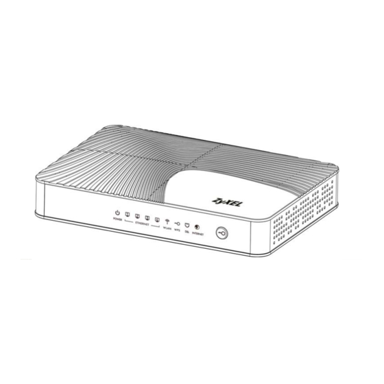
Chapter 1 Introduction Figure 2 Wireless Access Example 1.5 General Hardware Features Figure 3 General Hardware Features The following table describes the LEDs.. Table 1 LED Descriptions COLOR STATUS DESCRIPTION Green The AMG1302/AMG1202-TSeries is receiving power and ready for use. Blinking The AMG1302/AMG1202-TSeries is self-testing. -
Page 18: Using The Wps Button
Chapter 1 Introduction Table 1 LED Descriptions COLOR STATUS DESCRIPTION Green The wireless network is activated. Blinking The AMG1302/AMG1202-TSeries is communicating with other wireless clients. (WPS/WLAN) Green Blinking The AMG1302/AMG1202-TSeries is setting up a WPS connection. The wireless network is not activated. Green The DSL line is up. -
Page 19: The Reset Button
Chapter 1 Introduction 1.7 The RESET Button If you forget your password or cannot access the web configurator, you will need to use the RESET button at the back of the device to reload the factory-default configuration file. This means that you will lose all configurations that you had previously and the user name and password will be reset to the default. - Page 20 Chapter 1 Introduction AMG1302/AMG1202-TSeries User’s Guide...
-
Page 21: Introducing The Web Configurator
H A PT ER Introducing the Web Configurator 2.1 Overview The web configurator is an HTML-based management interface that allows easy device setup and management via Internet browser. Use Internet Explorer 6.0 and later versions, Mozilla Firefox 3 and later versions, or Safari 2.0 and later versions. The recommended screen resolution is 1024 by 768 pixels. - Page 22 Chapter 2 Introducing the Web Configurator Note: For security reasons, the AMG1302/AMG1202-TSeries automatically logs you out if you do not use the web configurator for five minutes (default). If this happens, log in again. The following screen displays if you have not yet changed your password. It is strongly recommended you change the default password.
-
Page 23: The Web Configurator Layout
Chapter 2 Introducing the Web Configurator 2.2 The Web Configurator Layout Click Connection Status > System Info to show the following screen. Figure 7 Web Configurator Layout Screen AMG1302/AMG1202-TSeries User’s Guide... -
Page 24: Title Bar
Chapter 2 Introducing the Web Configurator As illustrated above, the main screen is divided into these parts: • A - title bar • B - main window • C - navigation panel 2.2.1 Title Bar The title bar shows the following icon in the upper right corner. Click this icon to log out of the web configurator. -
Page 25: Main Window
Chapter 2 Introducing the Web Configurator 2.2.2 Main Window The main window displays information and configuration fields. It is discussed in the rest of this document. After you click System Info on the Connection Status screen, the System Info screen is displayed. - Page 26 Chapter 2 Introducing the Web Configurator Table 2 Navigation Panel Summary LINK FUNCTION Home LAN Setup Use this screen to configure LAN TCP/IP settings, and other Networking advanced properties. Static DHCP Use this screen to assign specific IP addresses to individual MAC addresses.
- Page 27 Chapter 2 Introducing the Web Configurator Table 2 Navigation Panel Summary LINK FUNCTION Certificates Local Certificates Use this screen to export self-signed certificates or certification requests and import the AMG1302/AMG1202-TSeries’s CA-signed certificates. Trusted CA Use this screen to save CA certificates to the AMG1302/AMG1202- TSeries.
- Page 28 Chapter 2 Introducing the Web Configurator AMG1302/AMG1202-TSeries User’s Guide...
-
Page 29: Internet / Wireless Setup Wizard
H A PT ER Internet / Wireless Setup Wizard 3.1 Overview Use the wizard setup screens to configure your system for Internet access with the information given to you by your ISP. Note: See the advanced menu chapters for background information on these fields. 3.2 Internet / Wireless Wizard Setup After you enter the password to access the web configurator, click the Wizard icon ( ) in... - Page 30 Chapter 3 Internet / Wireless Setup Wizard Select your Time Zone from the drop-down menu, and click Next. Figure 8 Wizard Welcome Enter your Internet access information in the wizard screen exactly as your service provider gave it to you. Leave the defaults in any fields for which you were not given information.
- Page 31 Chapter 3 Internet / Wireless Setup Wizard The following table describes the fields in this screen. Table 3 Internet Access Wizard Setup: IPoA Configuration LABEL DESCRIPTION Encapsulation Select the encapsulation type your ISP uses from the Encapsulation drop-down list box: IPoA, ENET ENCAP, PPPoA, or PPPoE. Multiplex Select the multiplexing method used by your ISP from the Multiplex drop-down list box either VC-based or LLC-based.
- Page 32 Chapter 3 Internet / Wireless Setup Wizard The following table describes the fields in this screen. Table 4 Internet Connection with ENET ENCAP LABEL DESCRIPTION Encapsulation Select the encapsulation type your ISP uses from the Encapsulation drop-down list box: IPoA, ENET ENCAP, PPPoA, or PPPoE. Multiplex Select the multiplexing method used by your ISP from the Multiplex drop-down list box either VC-based or LLC-based.
- Page 33 Chapter 3 Internet / Wireless Setup Wizard Figure 11 Internet Connection with PPPoA The following table describes the fields in this screen. Table 5 Internet Connection with PPPoA LABEL DESCRIPTION Encapsulation Select the encapsulation type your ISP uses from the Encapsulation drop-down list box: IPoA, ENET ENCAP, PPPoA, or PPPoE.
- Page 34 Chapter 3 Internet / Wireless Setup Wizard Figure 12 Internet Connection with PPPoE The following table describes the fields in this screen. Table 6 Internet Connection with PPPoE LABEL DESCRIPTION User Name Enter the user name exactly as your ISP assigned. If assigned a name in the form user@domain where domain identifies a service name, then enter both components exactly as given.
- Page 35 Chapter 3 Internet / Wireless Setup Wizard • If the Internet connection fails, check to see if your account is activated. After you configure the Internet access information, use the following screen to set up your wireless LAN. Check the Wireless Service box to enable wireless connection on the ZyXEL device. Configure your wireless settings in this screen.
- Page 36 Chapter 3 Internet / Wireless Setup Wizard Note: The wireless stations and AMG1302/AMG1202-TSeries must use the same SSID and channel ID for wireless communication. The configuration settings are saved and applied. Click Close to complete the Internet / Wireless setup. Figure 14 Results Summary Launch your web browser and navigate to www.zyxel.com.
-
Page 37: Tutorials
H A PT ER Tutorials 4.1 Overview This chapter shows you how to use the AMG1302/AMG1202-TSeries’s various features. • Setting Up Your DSL Connection, see page 37 • IPv6 Address Configuration, see page 39 • Setting Up a Secure Wireless Network, see page 40 •... -
Page 38: Account Configuration
Chapter 4 Tutorials Account Configuration For this example, the interface type is ADSL and the connection has the following information. General Mode Router Encapsulation PPPoE User Name 1234@DSL-Ex.com Password ABCDEF! Service Name My DSL Multiplex IPv6/IPv4 Dual Enabled Stack Auto Authentication Others IP Address: Obtain IP Address Automatically... -
Page 39: Ipv6 Address Configuration
Chapter 4 Tutorials Go to Network Setting > Broadband, enter or select these values and click Apply. This completes your DSL WAN connection setting. 4.3 IPv6 Address Configuration If the ISP’s network supports IPv6, the ISP may assign an IPv6 address to the AMG1302/AMG1202- TSeries automatically. -
Page 40: Setting Up A Secure Wireless Network
Chapter 4 Tutorials IPv6 IPv6 IPv6 In the Network Setting > Broadband screen’s IPv6 Address configuration section, select Obtain an IP Address Automatically. In the DHCP IPv6 field select DHCP to obtain an IPv6 address from a DHCPv6 server. In the DHCP PD field select Enable to have the AMG1302/ AMG1202-TSeries pass the WAN prefix to LAN hosts. -
Page 41: Using Wps
Chapter 4 Tutorials Click Network Setting > Wireless to open the General screen. Configure the screen using the provided parameters (see page 40). Click Apply. Click Network Setting > Wireless > Advanced and make sure 802.11b+g+n is selected in the 802.11 Mode field. - Page 42 Chapter 4 Tutorials AMG1202-TSeries as the AP and ZyXEL NWD210N as the wireless client which connects to the notebook. Note: The wireless client must be a WPS-aware device (for example, a WPS USB adapter or PCMCIA card). There are two WPS methods to set up the wireless client settings: •...
-
Page 43: Wireless Client
Chapter 4 Tutorials The following figure shows you an example of how to set up a wireless network and its security by pressing a button on both AMG1302/AMG1202-TSeries and wireless client. Example WPS Process: PBC Method The Device Wireless Client WITHIN 2 MINUTES Press and hold for 5 seconds... - Page 44 Chapter 4 Tutorials Click the Start and Register buttons (or the button next to the PIN field) on both the wireless client utility screen and the AMG1302/AMG1202-TSeries’s WPS screen within two minutes. The AMG1302/AMG1202-TSeries authenticates the wireless client and sends the proper configuration settings to the wireless client.
-
Page 45: Connecting Wirelessly To Your Amg1302/Amg1202-Tseries
Chapter 4 Tutorials Example WPS Process: PIN Method Wireless Client The Device WITHIN 2 MINUTES Authentication by PIN SECURITY INFO COMMUNICATION 4.4.3 Connecting Wirelessly to your AMG1302/AMG1202-TSeries This section describes how to connect wirelessly to your AMG1302/AMG1202-TSeries. The connection procedure is shown here using Windows XP as an example. Right-click the wireless adapter icon which appears in the bottom right of your computer monitor. - Page 46 Chapter 4 Tutorials Tutorial: Status Select the AMG1302/AMG1202-TSeries’s SSID name and click Connect (A). The SSID “SecureWirelessNetwork” is given here as an example. Tutorial: Status You are prompted to enter a password. Enter it and click Connect. Tutorial: Status You may have to wait several minutes while your computer connects to the wireless network. You should now be securely connected wirelessly to the AMG1302/AMG1202-TSeries.
-
Page 47: Configuring The Mac Address Filter For Restricting Wireless Internet Access
Chapter 4 Tutorials Congratulations! Your computer is now ready to connect to the Internet wirelessly through your AMG1302/AMG1202-TSeries. Note: If you cannot connect wirelessly to the AMG1302/AMG1202-TSeries, check you have selected the correct SSID and entered the correct security key. If that does not work, ensure your wireless network adapter is enabled by clicking on the wireless adapter icon and clicking Enable. -
Page 48: Setting Up Nat Forwarding For A Game Server
Chapter 4 Tutorials C:\>ipconfig /all Ethernet adapter Wireless Network Connection: Media State ... : Media connected Description ... : Wireless USB Adapter Physical Address. -
Page 49: Port Forwarding
Chapter 4 Tutorials Tutorial: NAT Port Forwarding Setup D=192.168.1.34 port 666 4.6.1 Port Forwarding Thomas needs to configure the port settings and IP address on the AMG1302/AMG1202-TSeries. Traffic should be forwarded to port 666 of the Doom server computer which has an IP address of 192.168.1.34. -
Page 50: Configuring Firewall Rules To Allow A Specified Service
Chapter 4 Tutorials Service Name Select User Define. Start/End Ports Enter 666 as the Start and End port. Server IP Address Enter the IP address of the Doom server (192.168.1.34 for this example). The screen should look as follows. Click Apply. The port forwarding settings you configured appear in the table. - Page 51 Chapter 4 Tutorials Tutorial: NAT Port Forwarding Setup Click Security > Firewall and select Custom. Click Apply to save your settings. Tutorial: Advanced > QoS Click the Rules tab. In the Packet Direction field select WAN to LAN and click Add. Tutorial: Advanced >...
- Page 52 Chapter 4 Tutorials Tutorial: Advanced > QoS > Queue Setup In the Add New Firewall Rule screen, select Active. In the Available Services field, select the service you configured, My_Service. Click OK. Tutorial: Advanced > QoS > Queue Setup AMG1302/AMG1202-TSeries User’s Guide...
-
Page 53: Configuring Static Route For Routing To Another Network
Chapter 4 Tutorials The firewall rule you configured appears in the table. The AMG1302/AMG1202-TSeries allows traffic from the WAN to LAN if it matches port 123. 4.8 Configuring Static Route for Routing to Another Network In order to extend your Intranet and control traffic flowing directions, you may connect a router to the AMG1302/AMG1202-TSeries’s LAN. - Page 54 Chapter 4 Tutorials This tutorial uses the following example IP settings: Table 8 IP Settings in this Tutorial DEVICE / COMPUTER IP ADDRESS The AMG1302/AMG1202-TSeries’s 172.16.1.1 The AMG1302/AMG1202-TSeries’s 192.168.1.1 192.168.1.34 R’s N1 192.168.1.253 R’s N2 192.168.10.2 192.168.10.33 To configure a static route to route traffic from N1 to N2: Log into the AMG1302/AMG1202-TSeries’s Web Configurator.
-
Page 55: Port Binding Configuration
Chapter 4 Tutorials Click OK. Now B should be able to receive traffic from A. You may need to additionally configure B’s firewall settings to allow specific traffic to pass through. 4.9 Port Binding Configuration This tutorial shows you how to configure port binding for WAN connections with different ATM QoS settings for different types of traffic. - Page 56 Chapter 4 Tutorials To configure bandwidth for the data connection, select UBR with PCR in the ATM QoS Type field. Click Apply. AMG1302/AMG1202-TSeries User’s Guide...
- Page 57 Chapter 4 Tutorials To configure dedicated bandwidth of 400 kbps for the VoIP connection, select CBR in the ATM QoS Type field and enter the Peak Cell Rate as 943 (divide the bandwidth 400000 bps by 424). Click Apply to save the settings. To configure variable bandwidth of 2 Mbps for MOD data connection, select Realtime VBR in the ATM QoS Type field.
-
Page 58: Configuring Port Binding
Chapter 4 Tutorials Configured WAN connections can be viewed by clicking the More Connections tab under Network Setting > Broadband. See the WAN Setup chapter (Chapter 6 on page 73) for more information on configuring WAN connections and ATM QoS settings. 4.9.2 Configuring Port Binding You can then group specific WAN PVCs with LAN ports or WLANs, so traffic from these ports is forwarded through specific WAN PVCs. -
Page 59: Configuring Qos To Prioritize Traffic
Chapter 4 Tutorials The configured groups can be viewed by clicking the Port Binding Summary button. See the Port Binding chapter (Chapter 12 on page 161) for more details on configuring port binding. 4.10 Configuring QoS to Prioritize Traffic This section contains tutorials on how you can configure the QoS screen. Let’s say you are a team leader of a small sales branch office. - Page 60 Chapter 4 Tutorials Click Network Setting > QoS and check Active QoS. Click Apply. Tutorial: Advanced > QoS Go to Network Setting > QoS > Queue Setup. Click the Edit icon next to an entry to configure a queue. Select Active and give it a name (Queue1 in this example). Select WAN in the Interface field and 1 in the Priority and Weight fields.
- Page 61 Chapter 4 Tutorials Tutorial: Advanced > QoS > Class Setup AMG1302/AMG1202-TSeries User’s Guide...
-
Page 62: Access The Amg1302/Amg1202-Tseries From The Internet Using Ddns
Chapter 4 Tutorials Interface Select From LAN. To Queue Link this to a queue created in the Network Setting > QoS > Queue Setup screen, which is the 1 queue created in this example. Source MAC Address Type the MAC address of your computer - AA:FF:AA:FF:AA:FF. -
Page 63: Configuring Ddns On Your Amg1302/Amg1202-Tseries
Chapter 4 Tutorials Apply for a user account. This tutorial uses UserName1 and 12345 as the username and password. Log into www.dyndns.org using your account. Add a new DDNS host name. This tutorial uses the following settings as an example. •... - Page 64 Chapter 4 Tutorials AMG1302/AMG1202-TSeries User’s Guide...
-
Page 65: Technical Reference
Technical Reference... -
Page 67: Connection Status And System Info Screens
H A PT ER Connection Status and System Info Screens 5.1 Overview After you log into the web configurator, the Connection Status screen appears. This shows the network connection status of the AMG1302/AMG1202-TSeries and clients connected to it. Use the System Info screen to look at the current status of the device, system resources and interfaces (LAN, WAN, WLAN). -
Page 68: The System Info Screen
Chapter 5 Connection Status and System Info Screens Figure 16 Connection Status: List View In Icon View, if you want to view information about a client, click the client’s name and then click on Info. In List View, you can also view the client’s information. 5.3 The System Info Screen Click Connection Status >... - Page 69 Chapter 5 Connection Status and System Info Screens Table 10 System Info Screen LABEL DESCRIPTION Refresh Interval Select how often you want the AMG1302/AMG1202-TSeries to update this screen from the drop-down list box. Device Information Host Name This field displays the AMG1302/AMG1202-TSeries system name. It is used for identification.
- Page 70 Chapter 5 Connection Status and System Info Screens LABEL DESCRIPTION DHCP This field displays what DHCP services the AMG1302/AMG1202-TSeries is providing to the LAN. Choices are: Server - The AMG1302/AMG1202-TSeries is a DHCP server in the LAN. It assigns IP addresses to other computers in the LAN.
- Page 71 Chapter 5 Connection Status and System Info Screens LABEL DESCRIPTION System Up Time This field displays how long the AMG1302/AMG1202-TSeries has been running since it last started up. The AMG1302/AMG1202-TSeries starts up when you plug it in, when you restart it (Maintenance > Reboot), or when you reset it (see Chapter 1 on page 19).
- Page 72 Chapter 5 Connection Status and System Info Screens AMG1302/AMG1202-TSeries User’s Guide...
-
Page 73: Broadband
H A PT ER Broadband 6.1 Overview This chapter describes the AMG1302/AMG1202-TSeries’s Broadband screens. Use these screens to configure your AMG1302/AMG1202-TSeries for Internet access. A WAN (Wide Area Network) connection is an outside connection to another network or the Internet. It connects your private networks (such as a LAN (Local Area Network) and other networks, so that a computer in one location can communicate with computers in other locations. -
Page 74: Before You Begin
Chapter 6 Broadband devices in other networks. It can be static (fixed) or dynamically assigned by the ISP each time the AMG1302/AMG1202-TSeries tries to access the Internet. If your ISP assigns you a static WAN IP address, they should also assign you the subnet mask and DNS server IP address(es) (and a gateway IP address if you use the Ethernet or ENET ENCAP encapsulation method). - Page 75 Chapter 6 Broadband Figure 19 Network Setting > Broadband > Internet Connection > Auto Sync Up AMG1302/AMG1202-TSeries User’s Guide...
- Page 76 Chapter 6 Broadband Figure 20 Network Setting > Broadband > Internet Connection > Ethernet(ETH1) AMG1302/AMG1202-TSeries User’s Guide...
- Page 77 Chapter 6 Broadband The following table describes the labels in this screen. Table 11 Network Setting > Broadband > Internet Connection LABEL DESCRIPTION Line Type Select the DSL mode supported by your ISP. Use Auto Sync-Up if you are not sure which mode to choose from. The AMG1302/ AMG1202-TSeries dynamically diagnoses the mode supported by the ISP and selects the best compatible one for your connection.
- Page 78 Chapter 6 Broadband Table 11 Network Setting > Broadband > Internet Connection (continued) LABEL DESCRIPTION This option is available if you select Router in the Mode field. The valid range for the VCI is 32 to 65535 (0 to 31 is reserved for local management of ATM traffic).
-
Page 79: Advanced Setup
Chapter 6 Broadband Table 11 Network Setting > Broadband > Internet Connection (continued) LABEL DESCRIPTION WAN Identifier Type Select Manual to manually enter a WAN Identifier as the interface ID to identify the WAN interface. The WAN Identifier is appended to the IPv6 address prefix to create the routable global IPv6 address. - Page 80 Chapter 6 Broadband The following table describes the labels in this screen. Table 12 Network Setting > Broadband > Internet Connection: Advanced Setup LABEL DESCRIPTION RIP Direction RIP (Routing Information Protocol) allows a router to exchange routing information with other routers. Use this field to control how much routing information the AMG1302/AMG1202-TSeries sends and receives on the subnet.
-
Page 81: The More Connections Screen
Chapter 6 Broadband 6.3 The More Connections Screen The AMG1302/AMG1202-TSeries allows you to configure more than one Internet access connection. To configure additional Internet access connections click Network Setting > Broadband > More Connections. The screen differs by the encapsulation you select. When you use the Broadband > Internet Connection screen to set up Internet access, you are configuring the first WAN connection. -
Page 82: More Connections Edit
Chapter 6 Broadband Table 13 Network Setting > Broadband > More Connections (continued) LABEL DESCRIPTION This is an index number indicating the number of the corresponding connection. Active This field indicates whether the connection is active or not. Clear the check box to disable the connection. Select the check box to enable it. Node Name This is the name you gave to the Internet connection. - Page 83 Chapter 6 Broadband Figure 23 Network Setting > Broadband > More Connections: Edit The following table describes the labels in this screen. Table 14 Network Setting > Broadband > More Connections: Edit LABEL DESCRIPTION General Active Select the check box to activate or clear the check box to deactivate this connection. AMG1302/AMG1202-TSeries User’s Guide...
- Page 84 Chapter 6 Broadband Table 14 Network Setting > Broadband > More Connections: Edit (continued) LABEL DESCRIPTION Node Name Enter a unique, descriptive name of up to 13 ASCII characters for this connection. Mode Select Router from the drop-down list box if your ISP allows multiple computers to share an Internet account.
-
Page 85: Configuring More Connections Advanced Setup
Chapter 6 Broadband 6.3.2 Configuring More Connections Advanced Setup Use this screen to edit your AMG1302/AMG1202-TSeries's advanced WAN settings. Click the Advanced Setup arrow icon in the More Connections Edit screen. The screen appears as shown. Figure 24 Network Setting > Broadband > More Connections: Edit: Advanced Setup The following table describes the labels in this screen. -
Page 86: Wan Technical Reference
Chapter 6 Broadband Table 15 Network Setting > Broadband > More Connections: Edit: Advanced Setup (continued) LABEL DESCRIPTION The Maximum Transmission Unit (MTU) defines the size of the largest packet allowed on an interface or connection. Enter the MTU in this field. For ENET ENCAP, the MTU value is 1500. -
Page 87: Multiplexing
Chapter 6 Broadband AMG1202-TSeries does that part of the task. Furthermore, with NAT, all of the LANs’ computers will have access. 6.4.1.3 PPPoA PPPoA stands for Point to Point Protocol over ATM Adaptation Layer 5 (AAL5). A PPPoA connection functions like a dial-up Internet connection. The AMG1302/AMG1202-TSeries encapsulates the PPP session based on RFC1483 and sends it through an ATM PVC (Permanent Virtual Circuit) to the Internet Service Provider’s (ISP) DSLAM (Digital Subscriber Line (DSL) Access Multiplexer). -
Page 88: Nailed-Up Connection (Ppp)
Chapter 6 Broadband IP Assignment with PPPoA or PPPoE Encapsulation If you have a dynamic IP, then the IP Address and Gateway IP Address fields are not applicable (N/A). If you have a Static IP Address assigned by your ISP, then they should also assign you a Subnet Mask and a Gateway IP Address. -
Page 89: Atm Traffic Classes
Chapter 6 Broadband Sustained Cell Rate (SCR) is the mean cell rate of each bursty traffic source. It specifies the maximum average rate at which cells can be sent over the virtual connection. SCR may not be greater than the PCR. Maximum Burst Size (MBS) is the maximum number of cells that can be sent at the PCR. - Page 90 Chapter 6 Broadband The VBR-nRT (non real-time Variable Bit Rate) type is used with bursty connections that do not require closely controlled delay and delay variation. It is commonly used for "bursty" traffic typical on LANs. PCR and MBS define the burst levels, SCR defines the minimum level. An example of an VBR-nRT connection would be non-time sensitive data file transfers.
-
Page 91: Wireless Lan
H A PT ER Wireless LAN 7.1 Overview This chapter describes how to perform tasks related to setting up and optimizing your wireless network, including the following. • Turning the wireless connection on or off. • Configuring a name, wireless channel and security for the network. •... -
Page 92: What You Need To Know About Wireless
Chapter 7 Wireless LAN 7.1.2 What You Need to Know About Wireless Wireless Basics “Wireless” is essentially radio communication. In the same way that walkie-talkie radios send and receive information over the airwaves, wireless networking devices exchange information with one another. - Page 93 Chapter 7 Wireless LAN Figure 26 Network Setting > Wireless > General The following table describes the labels in this screen. Table 16 Network Setting > Wireless > General LABEL DESCRIPTION Wireless Network Setup Wireless Select Enable Wireless LAN to activate wireless LAN. Wireless Network Settings Wireless The SSID (Service Set IDentity) identifies the service set with which a wireless device is...
-
Page 94: No Security
Chapter 7 Wireless LAN Table 16 Network Setting > Wireless > General LABEL DESCRIPTION Security Mode Select Basic (WEP) or More Secure (WPA(2)-PSK, WPA(2)) to add security on this wireless network. The wireless clients which want to associate to this network must have same wireless security settings as the AMG1302/AMG1202-TSeries. -
Page 95: More Secure (Wpa(2)-Psk)
Chapter 7 Wireless LAN In order to configure and enable WEP encryption, click Network Setting > Wireless to display the General screen, then select Basic as the security level. Figure 28 Wireless > General: Basic (WEP) The following table describes the wireless LAN security labels in this screen. Table 17 Wireless >... -
Page 96: Wpa(2) Authentication
Chapter 7 Wireless LAN Click Network Setting > Wireless to display the General screen. Select More Secure as the security level. Then select WPA-PSK or WPA2-PSK from the Security Mode list. Figure 29 Wireless > General: More Secure: WPA(2)-PSK The following table describes the wireless LAN security labels in this screen. Table 18 Wireless >... - Page 97 Chapter 7 Wireless LAN The WPA security mode is a security subset of WPA2. It requires the presence of a RADIUS server on your network in order to validate user credentials. This encryption standard is slightly older than WPA2 and therefore is more compatible with older devices. Click Network Setting >...
-
Page 98: The More Ap Screen
Chapter 7 Wireless LAN Table 19 Wireless > General: More Secure: WPA(2) (continued) LABEL DESCRIPTION Group Key Update The Group Key Update Timer is the rate at which the RADIUS server sends a new Timer group key out to all clients. Encryption Select the encryption type for data encryption. - Page 99 Chapter 7 Wireless LAN Figure 32 More AP: Edit The following table describes the fields in this screen. Table 21 More AP: Edit LABEL DESCRIPTION Wireless Network Setup Wireless Select Enable Wireless LAN to activate wireless LAN. Wireless Network Settings Wireless Network Name The SSID (Service Set IDentity) identifies the service set with which a wireless (SSID)
-
Page 100: The Mac Authentication Screen
Chapter 7 Wireless LAN Table 21 More AP: Edit LABEL DESCRIPTION Security Mode Select Basic (WEP) or More Secure (WPA(2)-PSK, WPA(2)) to add security on this wireless network. The wireless clients which want to associate to this network must have same wireless security settings as the AMG1302/AMG1202-TSeries. After you select to use a security, additional options appears in this screen. -
Page 101: The Wps Screen
Chapter 7 Wireless LAN Table 22 Network Setting > Wireless > MAC Authentication (continued) LABEL DESCRIPTION Add new MAC Click this if you want to add a new MAC address entry to the MAC filter list below. address Enter the MAC addresses of the wireless devices that are allowed or denied access to the AMG1302/AMG1202-TSeries in these address fields. - Page 102 Chapter 7 Wireless LAN Figure 34 Network Setting > Wireless > WPS The following table describes the labels in this screen. Table 23 Network Setting > Wireless > WPS LABEL DESCRIPTION General Select Enable to activate WPS on the AMG1302/AMG1202-TSeries. Otherwise, select Disable to deactivate WPS.
-
Page 103: The Wds Screen
Chapter 7 Wireless LAN Table 23 Network Setting > Wireless > WPS LABEL DESCRIPTION Register Enter the PIN of the device that you are setting up a WPS connection with and click Register to authenticate and add the wireless device to your wireless network. You can find the PIN either on the outside of the device, or by checking the device’s settings. -
Page 104: The Wmm Screen
Chapter 7 Wireless LAN Note: At the time of writing, WDS is compatible with other ZyXEL APs only. Not all models support WDS links. Check your other AP’s documentation. Click Network Setting > Wireless > WDS. The following screen displays. Figure 35 Network Setting >... -
Page 105: The Scheduling Screen
Chapter 7 Wireless LAN Click Network Setting > Wireless > WMM. The following screen displays. Figure 36 Network Setting > Wireless > WMM The following table describes the labels in this screen. Table 25 Network Setting > Wireless > WMM LABEL DESCRIPTION Enable WMM of... -
Page 106: The Advanced Screen
Chapter 7 Wireless LAN Table 26 Network Setting > Wireless > Scheduling LABEL DESCRIPTION Time (24-Hour Specify a time frame during which the schedule would apply. Format) For example, if you set the time range from 12:00 to 23:00, the wireless LAN will be turned on only during this time period. -
Page 107: Wireless Lan Technical Reference
Chapter 7 Wireless LAN Table 27 Network Setting > Wireless> Advanced LABEL DESCRIPTION 802.11 Mode Select 802.11b Only to allow only IEEE 802.11b compliant WLAN devices to associate with the AMG1302/AMG1202-TSeries. Select 802.11g Only to allow only IEEE 802.11g compliant WLAN devices to associate with the AMG1302/AMG1202-TSeries. - Page 108 Chapter 7 Wireless LAN • An “infrastructure” type of network has one or more access points and one or more wireless clients. The wireless clients connect to the access points. • An “ad-hoc” type of network is one in which there is no access point. Wireless clients connect to one another in order to exchange information.
-
Page 109: Additional Wireless Terms
Chapter 7 Wireless LAN variety of networks to exist in the same place without interfering with one another. When you create a network, you must select a channel to use. Since the available unlicensed spectrum varies from one country to another, the number of available channels also varies. - Page 110 Chapter 7 Wireless LAN her favorite movie is Vanishing Point (which you know was made in 1971) you could use “70dodchal71vanpoi” as your security key. The following sections introduce different types of wireless security you can set up in the wireless network.
-
Page 111: Signal Problems
Chapter 7 Wireless LAN 7.10.3.4 Encryption Wireless networks can use encryption to protect the information that is sent in the wireless network. Encryption is like a secret code. If you do not know the secret code, you cannot understand the message. The types of encryption you can choose depend on the type of authentication. -
Page 112: Bss
Chapter 7 Wireless LAN 7.10.5 BSS A Basic Service Set (BSS) exists when all communications between wireless stations or between a wireless station and a wired network client go through one access point (AP). Intra-BSS traffic is traffic between wireless stations in the BSS. When Intra-BSS traffic blocking is disabled, wireless station A and B can access the wired network and communicate with each other. -
Page 113: Wireless Distribution System (Wds)
Chapter 7 Wireless LAN • MBSSID should not replace but rather be used in conjunction with 802.1x security. 7.10.7 Wireless Distribution System (WDS) The AMG1302/AMG1202-TSeries can act as a wireless network bridge and establish WDS (Wireless Distribution System) links with other APs. You need to know the MAC addresses of the APs you want to link to. - Page 114 Chapter 7 Wireless LAN Look for a WPS button on each device. If the device does not have one, log into its configuration utility and locate the button (see the device’s User’s Guide for how to do this - for the AMG1302/ AMG1202-TSeries, see Section 7.6 on page 103).
- Page 115 Chapter 7 Wireless LAN The following figure shows a WPS-enabled wireless client (installed in a notebook computer) connecting to the WPS-enabled AP via the PIN method. Figure 42 Example WPS Process: PIN Method ENROLLEE REGISTRAR This device’s WPS PIN: 123456 Enter WPS PIN from other device: START...
- Page 116 Chapter 7 Wireless LAN Figure 43 How WPS works ACTIVATE ACTIVATE WITHIN 2 MINUTES WPS HANDSHAKE ENROLLEE REGISTRAR SECURE TUNNEL SECURITY INFO COMMUNICATION The roles of registrar and enrollee last only as long as the WPS setup process is active (two minutes).
- Page 117 Chapter 7 Wireless LAN Figure 44 WPS: Example Network Step 1 ENROLLEE REGISTRAR SECURITY INFO CLIENT 1 In step 2, you add another wireless client to the network. You know that Client 1 supports registrar mode, but it is better to use AP1 for the WPS handshake with the new client since you must connect to the access point anyway in order to use the network.
- Page 118 Chapter 7 Wireless LAN Figure 46 WPS: Example Network Step 3 EXISTING CONNECTION CLIENT 1 REGISTRAR CLIENT 2 ENROLLEE 7.10.8.5 Limitations of WPS WPS has some limitations of which you should be aware. • WPS works in Infrastructure networks only (where an AP and a wireless client communicate). It does not work in Ad-Hoc networks (where there is no AP).
- Page 119 Chapter 7 Wireless LAN access point is the WPS registrar, the enrollee, or was not involved in the WPS handshake; a rogue device must still associate with the access point to gain access to the network. Check the MAC addresses of your wireless clients (usually printed on a label on the bottom of the device). If there is an unknown MAC address you can remove it or reset the AP.
- Page 120 Chapter 7 Wireless LAN AMG1302/AMG1202-TSeries User’s Guide...
-
Page 121: Home Networking
H A PT ER Home Networking 8.1 Overview A Local Area Network (LAN) is a shared communication system to which many networking devices are connected. It is usually located in one immediate area such as a building or floor of a building. Use the LAN screens to help you configure a LAN DHCP server and manage IP addresses. - Page 122 Chapter 8 Home Networking Subnet Mask Subnet masks determine the maximum number of possible hosts on a network. You can also use subnet masks to divide one network into multiple sub-networks. DHCP A DHCP (Dynamic Host Configuration Protocol) server can assign your AMG1302/AMG1202-TSeries an IP address, subnet mask, DNS and other routing information when it's turned on.
-
Page 123: Before You Begin
Chapter 8 Home Networking UPnP and ZyXEL Sexual has achieved UPnP certification from the Universal Plug and Play Forum UPnP™ Implementers Corp. (UIC). ZyXEL's UPnP implementation supports Internet Gateway Device (IGD) 1.0. Finding Out More Section 8.7 on page 131 for technical background information on LANs. - Page 124 Chapter 8 Home Networking The following table describes the fields in this screen. Table 30 Network Setting > Home Networking > LAN Setup LABEL DESCRIPTION LAN IP Setup IP Address Enter the LAN IP address you want to assign to your AMG1302/AMG1202-TSeries in dotted decimal notation, for example, 192.168.1.1 (factory default).
-
Page 125: The Static Dhcp Screen
Chapter 8 Home Networking 8.3 The Static DHCP Screen This table allows you to assign IP addresses on the LAN to specific individual computers based on their MAC Addresses. Every Ethernet device has a unique MAC (Media Access Control) address. The MAC address is assigned at the factory and consists of six pairs of hexadecimal characters, for example, 00:A0:C5:00:00:02. -
Page 126: The Upnp Screen
Chapter 8 Home Networking The following table describes the labels in this screen. Table 32 Static DHCP: Add/Edit LABEL DESCRIPTION MAC Address If you select Manual Input in the Select Device Info field, enter the MAC address of a computer on your LAN. IP Address If you select Manual Input in the Select Device Info field, enter the IP address that you want to assign to the computer on your LAN with the MAC address that you will... -
Page 127: Configuring The Lan Ip Alias Screen
Chapter 8 Home Networking When you use IP alias, you can also configure firewall rules to control access to the LAN's logical network (subnet). 8.5.1 Configuring the LAN IP Alias Screen Use this screen to change your AMG1302/AMG1202-TSeries’s IP alias settings. Click Network Setting >... - Page 128 Chapter 8 Home Networking Figure 52 Network Setting > Home Networking > IPv6 LAN Setup The following table describes the labels in this screen. Table 35 Network Setting > Home Networking > IPv6 LAN Setup LABEL DESCRIPTION IPv6 LAN Setup Link Local Address Select Manual to manually enter a link local address.
- Page 129 Chapter 8 Home Networking LABEL DESCRIPTION Lan Global Identifier Select Manual to manually enter a LAN Identifier as the interface ID to identify the Type LAN interface. The LAN Identifier is appended to the IPv6 address prefix to create the routable global IPv6 address.
- Page 130 Chapter 8 Home Networking LABEL DESCRIPTION Router Lifetime Enter the time in seconds that hosts should consider the AMG1302/AMG1202-TSeries to be the default router. Possible values for this field are 0-9000. Router Preference Select the router preference (Low, Medium or High) for the AMG1302/AMG1202- TSeries.
-
Page 131: Home Networking Technical Reference
Chapter 8 Home Networking 8.7 Home Networking Technical Reference This section provides some technical background information about the topics covered in this chapter. 8.7.1 LANs, WANs and the AMG1302/AMG1202-TSeries The actual physical connection determines whether the AMG1302/AMG1202-TSeries ports are LAN or WAN ports. -
Page 132: Lan Tcp/Ip
Chapter 8 Home Networking • Some ISPs choose to disseminate the DNS server addresses using the DNS server extensions of IPCP (IP Control Protocol) after the connection is up. If your ISP did not give you explicit DNS servers, chances are the DNS servers are conveyed through IPCP negotiation. The AMG1302/ AMG1202-TSeries supports the IPCP DNS server extensions through the DNS proxy feature. -
Page 133: Rip Setup
Chapter 8 Home Networking • 192.168.0.0 — 192.168.255.255 You can obtain your IP address from the IANA, from an ISP or it can be assigned from a private network. If you belong to a small organization and your Internet access is through an ISP, the ISP can provide you with the Internet addresses for your local networks. - Page 134 Chapter 8 Home Networking 224.0.0.1 is used for query messages and is assigned to the permanent group of all IP hosts (including gateways). All hosts must join the 224.0.0.1 group in order to participate in IGMP. The address 224.0.0.2 is assigned to the multicast routers group. At start up, the AMG1302/AMG1202-TSeries queries all directly connected networks to gather group membership.
-
Page 135: Static Route
H A PT ER Static Route 9.1 Overview The AMG1302/AMG1202-TSeries usually uses the default gateway to route outbound traffic from computers on the LAN to the Internet. To have the AMG1302/AMG1202-TSeries send data to devices not reachable through the default gateway, use static routes. For example, the next figure shows a computer (A) connected to the AMG1302/AMG1202-TSeries’s LAN interface. -
Page 136: What You Can Do In The Static Route Screens
Chapter 9 Static Route 9.1.1 What You Can Do in the Static Route Screens • Use the Static Route screens (Section 9.2 on page 136) to view and configure IP static routes on the AMG1302/AMG1202-TSeries. • Use the IPv6 Static Route screens (Section 9.3 on page 137) to view and configure IPv6 static routes on the AMG1302/AMG1202-TSeries. -
Page 137: Ipv6 Static Route
Chapter 9 Static Route Figure 56 Network Setting > Static Route Add/Edit The following table describes the labels in this screen. Table 37 Network Setting > Static Route Add/Edit LABEL DESCRIPTION Destination IP This parameter specifies the IP network address of the final destination. Routing is always Address based on network number. -
Page 138: Ipv6 Static Route Edit
Chapter 9 Static Route Table 38 Network Setting > Static Route > IPv6 Static Route LABEL DESCRIPTION Destination This parameter specifies the IP network address of the final destination. Routing is always based on network number. Prefix Length An IPv6 prefix length specifies how many most significant bits (starting from the left) in the address compose the network address. -
Page 139: Quality Of Service (Qos)
HAPTER Quality of Service (QoS) 10.1 Overview Use the QoS screen to set up your AMG1302/AMG1202-TSeries to use QoS for traffic management. Quality of Service (QoS) refers to both a network’s ability to deliver data with minimum delay, and the networking methods used to control bandwidth. QoS allows the AMG1302/AMG1202-TSeries to group and prioritize application traffic and fine-tune network performance. -
Page 140: What You Need To Know About Qos
Chapter 10 Quality of Service (QoS) • Use the Queue screen (Section 10.3 on page 141) to configure QoS settings on the AMG1302/ AMG1202-TSeries. • Use the Class Setup screen (Section 10.4 on page 143) to configure QoS settings on the AMG1302/AMG1202-TSeries. -
Page 141: The Queue Screen
Chapter 10 Quality of Service (QoS) The following table describes the labels in this screen. Table 40 Network Setting > QoS > General LABEL DESCRIPTION Active QoS Use this field to turn on QoS to improve your network performance. Traffic priority will be Select how the AMG1302/AMG1202-TSeries assigns priorities to various automatically assigned by incoming and outgoing traffic flows. -
Page 142: Adding A Qos Queue
Chapter 10 Quality of Service (QoS) Table 41 Network Setting > QoS > Queue LABEL DESCRIPTION Rate Limit This shows the maximum transmission rate allowed for traffic on this queue. Modify Click the Edit icon to edit the queue. Click the Delete icon to delete an existing queue. Note that subsequent rules move up by one when you take this action. -
Page 143: The Class Setup Screen
Chapter 10 Quality of Service (QoS) 10.4 The Class Setup Screen Use this screen to add, edit or delete QoS classifiers. A classifier groups traffic into data flows according to specific criteria such as the source address, destination address, source port number, destination port number or incoming interface. - Page 144 Chapter 10 Quality of Service (QoS) Figure 64 QoS > Class Setup Add/Edit AMG1302/AMG1202-TSeries User’s Guide...
- Page 145 Chapter 10 Quality of Service (QoS) The following table describes the labels in this screen. Table 44 QoS > Class Setup Add/Edit LABEL DESCRIPTION Rule Index Select the rule’s index number from the drop-down list box. Class Configuration Active Use this field to enable or disable the QoS class rule. Ether Type Select a predefined application to configure a class for the matched traffic.
- Page 146 Chapter 10 Quality of Service (QoS) Table 44 QoS > Class Setup Add/Edit (continued) LABEL DESCRIPTION Mac Netmask Type the mask for the specified MAC address to determine which bits a packet’s MAC address should match. Enter “f” for each bit of the specified source MAC address that the traffic’s MAC address should match.
-
Page 147: The Qos Game List Screen
Chapter 10 Quality of Service (QoS) Table 44 QoS > Class Setup Add/Edit (continued) LABEL DESCRIPTION IP Precedence Enter a range from 0 to 7 to re-assign IP precedence to matched traffic. 0 is the lowest Mark priority and 7 is the highest. Type Of Select a type of service to re-assign the priority level to matched traffic. -
Page 148: Qos Technical Reference
Chapter 10 Quality of Service (QoS) The following table describes the labels in this screen. Table 45 Network Setting > QoS > Game List LABEL DESCRIPTION Enable Game List Select this to have QoS give the highest priority to traffic for the games you specify. This priority is higher than the other QoS queues. -
Page 149: Automatic Priority Queue Assignment
Chapter 10 Quality of Service (QoS) 10.6.3 Automatic Priority Queue Assignment If you enable QoS on the AMG1302/AMG1202-TSeries, the AMG1302/AMG1202-TSeries can automatically base on the IEEE 802.1p priority level, IP precedence and/or packet length to assign priority to traffic which does not match a class. The following table shows you the internal layer-2 and layer-3 QoS mapping on the AMG1302/ AMG1202-TSeries. - Page 150 Chapter 10 Quality of Service (QoS) AMG1302/AMG1202-TSeries User’s Guide...
-
Page 151: Network Address Translation (Nat)
HAPTER Network Address Translation (NAT) 11.1 Overview This chapter discusses how to configure NAT on the AMG1302/AMG1202-TSeries. NAT (Network Address Translation - NAT, RFC 1631) is the translation of the IP address of a host in a packet, for example, the source address of an outgoing packet, used within one network to a different IP address known within another network. -
Page 152: The Nat General Screen
Chapter 11 Network Address Translation (NAT) Port Forwarding A port forwarding set is a list of inside (behind NAT on the LAN) servers, for example, web or FTP, that you can make visible to the outside world even though NAT makes your whole inside network appear as a single computer to the outside world. -
Page 153: The Port Forwarding Screen
Chapter 11 Network Address Translation (NAT) 11.3 The Port Forwarding Screen Use this screen to forward incoming service requests to the server(s) on your local network. You may enter a single port number or a range of port numbers to be forwarded, and the local IP address of the desired server. -
Page 154: Port Forwarding Rule Add/Edit
Chapter 11 Network Address Translation (NAT) Appendix F on page 305 for port numbers commonly used for particular services. Note: Make sure NAT is activated on the WAN connection before you configure a port forwarding rule for it. For the default WAN connection (PVC0), activate NAT in the Network Setting >... - Page 155 Chapter 11 Network Address Translation (NAT) Figure 69 Network Setting > NAT > Port Forwarding: Add/Edit The following table describes the fields in this screen. Table 50 Network Setting > NAT > Port Forwarding: Edit LABEL DESCRIPTION Active Click this check box to enable the rule. Service Name Enter a name to identify this port-forwarding rule.
-
Page 156: The Dmz Screen
Chapter 11 Network Address Translation (NAT) 11.4 The DMZ Screen If you need to allow packets from a specific WAN connection to your local network, NAT supports a default server IP address. A default server receives packets from the specified WAN connection and the ports that are not specified in the NAT Port Forwarding Setup screen. -
Page 157: What Nat Does
Chapter 11 Network Address Translation (NAT) a packet when the packet is still in the local network, while an inside global address (IGA) is the IP address of the same inside host when the packet is on the WAN side. The following table summarizes this information. -
Page 158: Nat Application
Chapter 11 Network Address Translation (NAT) Figure 71 How NAT Works NAT Table Inside Local Inside Global IP Address IP Address 192.168.1.10 IGA 1 192.168.1.13 192.168.1.11 IGA 2 192.168.1.12 IGA 3 192.168.1.13 IGA 4 192.168.1.12 192.168.1.10 IGA1 Inside Local Inside Global Address (ILA) Address (IGA) 192.168.1.11... - Page 159 Chapter 11 Network Address Translation (NAT) • One to One: In One-to-One mode, the AMG1302/AMG1202-TSeries maps one local IP address to one global IP address. • Many to One: In Many-to-One mode, the AMG1302/AMG1202-TSeries maps multiple local IP addresses to one global IP address. This is equivalent to SUA (for instance, PAT, port address translation), ZyXEL’s Single User Account feature that previous ZyXEL routers supported (the SUA Only option in today’s routers).
- Page 160 Chapter 11 Network Address Translation (NAT) AMG1302/AMG1202-TSeries User’s Guide...
-
Page 161: Port Binding
HAPTER Port Binding 12.1 Overview This chapter describes how to configure the port binding settings. Port binding allows you to aggregate port connections into logical groups. You may bind WAN PVCs to Ethernet ports and WLANs to specify how traffic is forwarded. Different ATM QoS settings can be specified for each WAN PVC to meet bandwidth requirements for the type of traffic to be transferred. -
Page 162: What You Can Do In The Port Binding Screens
Chapter 12 Port Binding If a WAN PVC is bound to an ethernet port, traffic from the ethernet port will only be forwarded through the specified WAN PVC and vice versa. If a port is not in a port binding group, traffic to and from the port will be forwarded according to the routing table. -
Page 163: Port Binding Summary Screen
Chapter 12 Port Binding Figure 75 Network Setting > Port Binding > Port Binding The following table describes the labels in this screen. Table 55 Network Setting > Port Binding > Port Binding LABEL DESCRIPTION Port Binding Active Activate or deactivate port binding for the port binding group. Group Index Select the index number for the port binding group. - Page 164 Chapter 12 Port Binding The following table describes the labels in this screen. Table 56 Network Setting > Port Binding > Port Binding Summary LABEL DESCRIPTION Group ID This field displays the group index number. Group port This field displays the ports included in the group. AMG1302/AMG1202-TSeries User’s Guide...
-
Page 165: Dynamic Dns Setup
HAPTER Dynamic DNS Setup 13.1 Overview Dynamic DNS allows you to update your current dynamic IP address with one or many dynamic DNS services so that anyone can contact you (in NetMeeting, CU-SeeMe, etc.). You can also access your FTP server or Web site on your own computer using a domain name (for instance myhost.dhs.org, where myhost is a name of your choice) that will never change instead of using an IP address that changes each time you reconnect. - Page 166 Chapter 13 Dynamic DNS Setup Figure 77 Network Setting > Dynamic DNS The following table describes the fields in this screen. Table 57 Network Setting > Dynamic DNS LABEL DESCRIPTION Dynamic DNS Setup Active Dynamic Select this check box to use dynamic DNS. Service Provider This is the website of your Dynamic DNS service provider.
-
Page 167: Filters
HAPTER Filters 14.1 Overview This chapter introduces three types of filters supported by the AMG1302/AMG1202-TSeries. You can configure rules to restrict traffic by IP addresses, MAC addresses, IPv6 addresses and/or URLs. 14.1.1 What You Can Do in the Filter Screens •... - Page 168 Chapter 14 Filters Figure 78 Security > Filter > IP/MAC Filter The following table describes the labels in this screen. Table 58 Security > Filter > IP/MAC Filter LABEL DESCRIPTION Rule Type Rule Type selection Select White List to specify traffic to allow and Black List to specify traffic to disallow.
- Page 169 Chapter 14 Filters Table 58 Security > Filter > IP/MAC Filter (continued) LABEL DESCRIPTION Subnet Mask Enter the IP subnet mask for the destination IP address. Port Number Enter the destination port of the packets that you wish to filter. The range of this field is 0 to 65535.
-
Page 170: Ipv6/Mac Filter
Chapter 14 Filters 14.3 IPv6/MAC Filter Use this screen to create and apply IPv6 filters. Click Security > Filter > IPv6/MAC Filter. The screen appears as shown. Figure 79 Security > Filter > IPv6/MAC Filter The following table describes the labels in this screen. Table 59 Security >... - Page 171 Chapter 14 Filters Table 59 Security > Filter > IPv6/MAC Filter (continued) LABEL DESCRIPTION Destination Prefix Length Enter the prefix length for the destination IPv6 address. ICMPv6 Type Select the ICMPv6 message type to filter. The following message types can be selected: 1 / Destination Unreachable: 0 - no route to destination;...
- Page 172 Chapter 14 Filters AMG1302/AMG1202-TSeries User’s Guide...
-
Page 173: Firewall
HAPTER Firewall 15.1 Overview This chapter shows you how to enable the AMG1302/AMG1202-TSeries firewall. Use the firewall to protect your AMG1302/AMG1202-TSeries and network from attacks by hackers on the Internet and control access to it. The firewall: • allows traffic that originates from your LAN computers to go to all other networks. •... -
Page 174: What You Need To Know About Firewall
Chapter 15 Firewall 15.1.2 What You Need to Know About Firewall SYN Attack A SYN attack floods a targeted system with a series of SYN packets. Each packet causes the targeted system to issue a SYN-ACK response. While the targeted system waits for the ACK that follows the SYN-ACK, it queues up all outstanding SYN-ACK responses on a backlog queue. -
Page 175: The Firewall General Screen
Chapter 15 Firewall Anti-Probing If an outside user attempts to probe an unsupported port on your AMG1302/AMG1202-TSeries, an ICMP response packet is automatically returned. This allows the outside user to know the AMG1302/AMG1202-TSeries exists. The AMG1302/AMG1202-TSeries supports anti-probing, which prevents the ICMP response packet from being sent. This keeps outsiders from discovering your AMG1302/AMG1202-TSeries when unsupported ports are probed. -
Page 176: The Default Action Screen
Chapter 15 Firewall The following table describes the labels in this screen. Table 60 Security > Firewall > General LABEL DESCRIPTION High This setting blocks all traffic to and from the Internet. Only local network traffic and LAN to WAN service (Telnet, FTP, HTTP, HTTPS, DNS, POP3, SMTP) is permitted. - Page 177 Chapter 15 Firewall The following table describes the labels in this screen. Table 61 Security > Firewall > Default Action LABEL DESCRIPTION Packet Direction This is the direction of travel of packets (LAN to Router, LAN to WAN, WAN to Router, WAN to LAN).
-
Page 178: The Rules Screen
Chapter 15 Firewall 15.4 The Rules Screen Click Security > Firewall > Rules to display the following screen. This screen displays a list of the configured firewall rules. Note the order in which the rules are listed. Note: The firewall configuration screen shown in this section is specific to the following devices: P-The ordering of your rules is very important as rules are applied in turn. -
Page 179: The Rules Add Screen
Chapter 15 Firewall Table 62 Security > Firewall > Rules LABEL DESCRIPTION Destination Interface This column displays the destination interface to which this firewall rule applies. This is the interface through which the traffic is destined to leave the AMG1302/ AMG1202-TSeries. - Page 180 Chapter 15 Firewall Figure 84 Security > Firewall > Rules > Add The following table describes the labels in this screen. Table 63 Security > Firewall > Rules > Add LABEL DESCRIPTION Active Select this option to enable this firewall rule. Action for Matched Use the drop-down list box to select whether to discard (Drop), deny and send an Packets...
-
Page 181: Customized Services
Chapter 15 Firewall Table 63 Security > Firewall > Rules > Add LABEL DESCRIPTION Address Type Do you want your rule to apply to packets with a particular (single) IP, a range of IP addresses (for instance, 192.168.1.10 to 192.169.1.50), a subnet or any IP address? Select an option from the drop-down list box that includes: Single Address, Range Address, Subnet Address and Any Address. -
Page 182: Customized Service Add/Edit
Chapter 15 Firewall Figure 85 Security > Firewall > Rules: Edit: Edit Customized Services The following table describes the labels in this screen. Table 64 Security > Firewall > Rules: Edit: Edit Customized Services LABEL DESCRIPTION This is the number of your customized port. Name This is the name of your customized service. - Page 183 Chapter 15 Firewall The following table describes the labels in this screen. Table 65 Security > Firewall > Rules: Edit: Edit Customized Services: Add/Edit LABEL DESCRIPTION Config Service Name Type a unique name for your custom port. Service Type Choose the IP port (TCP or UDP) that defines your customized port from the drop down list box.
-
Page 184: The Dos Screen
Chapter 15 Firewall 15.5 The DoS Screen Use this screen to enable DoS protection. Click Security > Firewall > Dos to display the following screen. Figure 87 Security > Firewall > Dos The following table describes the labels in this screen. Table 66 Security >... -
Page 185: Configuring Firewall Thresholds
Chapter 15 Firewall 15.5.1.1 Threshold Values If everything is working properly, you probably do not need to change the threshold settings as the default threshold values should work for most small offices. Tune these parameters when you believe the AMG1302/AMG1202-TSeries has been receiving DoS attacks that are not recorded in the logs or the logs show that the AMG1302/AMG1202-TSeries is classifying normal traffic as DoS attacks. -
Page 186: Firewall Technical Reference
Chapter 15 Firewall The following table describes the labels in this screen. Table 67 Security > Firewall > DoS > Advanced LABEL DESCRIPTION TCP SYN-Request This is the rate of new TCP half-open sessions per second that causes the firewall to Count start deleting half-open sessions. -
Page 187: Guidelines For Enhancing Security With Your Firewall
Chapter 15 Firewall • LAN to WAN These rules specify which computers on the LAN can access which computers or services on the WAN. By default, the AMG1302/AMG1202-TSeries’s stateful packet inspection drops packets traveling in the following directions: • WAN to LAN These rules specify which computers on the WAN can access which computers or services on the LAN. -
Page 188: Security Considerations
Chapter 15 Firewall 11 Protect against IP spoofing by making sure the firewall is active. 12 Keep the firewall in a secured (locked) room. 15.6.3 Security Considerations Note: Incorrectly configuring the firewall may block valid access or introduce security risks to the AMG1302/AMG1202-TSeries and your protected network. Use caution when creating or deleting firewall rules and test your rules after you configure them. - Page 189 Chapter 15 Firewall A computer on the LAN initiates a connection by sending out a SYN packet to a receiving server on the WAN. The AMG1302/AMG1202-TSeries reroutes the SYN packet through Gateway A on the LAN to the WAN. The reply from the WAN goes directly to the computer on the LAN without going through the AMG1302/AMG1202-TSeries.
- Page 190 Chapter 15 Firewall Figure 92 IP Alias Subnet 1 ISP 1 ISP 2 Subnet 2 AMG1302/AMG1202-TSeries User’s Guide...
-
Page 191: Parental Control
HAPTER Parental Control 16.1 Overview Parental control allows you to block web sites with the specific URL. You can also define time periods and days during which the AMG1302/AMG1202-TSeries performs parental control on a specific user. 16.2 The Parental Control Screen Use this screen to enable parental control, view the parental control rules and schedules. -
Page 192: Add/Edit Parental Control Rule
Chapter 16 Parental Control Table 68 Security > Parental Control (continued) LABEL DESCRIPTION Website Blocked This shows whether the website block is configured. If not, None will be shown. Modify Click the Edit icon to go to the screen where you can edit the rule. Click the Delete icon to delete an existing rule. - Page 193 Chapter 16 Parental Control Table 69 Parental Control: Add/Edit (continued) LABEL DESCRIPTION Parental Control Enter a descriptive name for the rule. Profile Name Home Network User Select the LAN user that you want to apply this rule to from the drop-down list box. If you select Custom, enter the LAN user’s MAC address.
- Page 194 Chapter 16 Parental Control AMG1302/AMG1202-TSeries User’s Guide...
-
Page 195: Certificate
HAPTER Certificate 17.1 Overview The AMG1302/AMG1202-TSeries can use certificates (also called digital IDs) to authenticate users. Certificates are based on public-private key pairs. A certificate contains the certificate owner’s identity and public key. Certificates provide a way to exchange public keys for use in authentication. 17.1.1 What You Can Do in this Chapter •... - Page 196 Chapter 17 Certificate • Web Server - This certificate secures HTTP connections. • SSH - This certificate secures remote connections. Click Security > Certificates to open the Local Certificates screen. Figure 95 Security > Certificates > Local Certificates The following table describes the labels in this screen. Table 70 Security >...
-
Page 197: The Trusted Ca Screen
Chapter 17 Certificate 17.4 The Trusted CA Screen Use this screen to view a summary list of certificates of the certification authorities that you have set the AMG1302/AMG1202-TSeries to accept as trusted. The AMG1302/AMG1202-TSeries accepts any valid certificate signed by a certification authority on this list as being trustworthy; thus you do not need to import any certificate that is signed by one of these certification authorities. -
Page 198: View Certificate
Chapter 17 Certificate Note: You must remove any spaces from the certificate’s filename before you can import the certificate. Figure 97 Trusted CA > Import The following table describes the labels in this screen. Table 72 Security > Certificates > Trusted CA > Import LABEL DESCRIPTION Certificate File... - Page 199 Chapter 17 Certificate Click Security > Certificates > Trusted CA to open the Trusted CA screen. Click the View icon to open the View Certificate screen. Figure 98 Trusted CA: View The following table describes the labels in this screen. Table 73 Trusted CA: View LABEL DESCRIPTION...
- Page 200 Chapter 17 Certificate AMG1302/AMG1202-TSeries User’s Guide...
-
Page 201: Logs
HAPTER Logs 18.1 Overview The web configurator allows you to choose which categories of events and/or alerts to have the AMG1302/AMG1202-TSeries log and then display the logs or have the AMG1302/AMG1202-TSeries send them to an administrator (as e-mail) or to a syslog server. 18.1.1 What You Can Do in this Chapter •... -
Page 202: The System Log Screen
Chapter 18 Logs Table 74 Syslog Severity Levels CODE SEVERITY Informational: The syslog contains an informational message. Debug: The message is intended for debug-level purposes. 18.2 The System Log Screen Click System Monitor > Log to open the System Log screen. Use the System Log screen to see the system logs for the categories that you select in the upper left drop-down list box. -
Page 203: Traffic Status
HAPTER Traffic Status 19.1 Overview Use the Traffic Status screens to look at network traffic status and statistics of the WAN, LAN interfaces and NAT. 19.1.1 What You Can Do in this Chapter • Use the WAN screen to view the WAN traffic statistics (Section 19.2 on page 203). -
Page 204: The Lan Status Screen
Chapter 19 Traffic Status Table 76 System Monitor > Traffic Status > WAN (continued) LABEL DESCRIPTION Packets Sent Data This indicates the number of transmitted packets on this interface. Error This indicates the number of frames with errors transmitted on this interface. Drop This indicates the number of outgoing packets dropped on this interface. -
Page 205: The Nat Screen
Chapter 19 Traffic Status Table 77 System Monitor > Traffic Status > LAN (continued) LABEL DESCRIPTION Data This indicates the number of transmitted packets on this interface. Error This indicates the number of frames with errors transmitted on this interface. Drop This indicates the number of outgoing packets dropped on this interface. - Page 206 Chapter 19 Traffic Status AMG1302/AMG1202-TSeries User’s Guide...
-
Page 207: User Account
HAPTER User Account 20.1 Overview You can configure system password for different user accounts in the User Account screen. 20.2 The User Account Screen Use the User Account screen to configure system password. Click Maintenance > User Account to open the following screen. Figure 103 Maintenance >... - Page 208 Chapter 20 User Account AMG1302/AMG1202-TSeries User’s Guide...
-
Page 209: Client
HAPTER TR-069 Client 21.1 Overview The AMG1302/AMG1202-TSeries supports TR-069 Amendment 1 (CPE WAN Management Protocol Release 2.0) and TR-069 Amendment 2 (CPE WAN Management Protocol v1.1, Release 3.0). TR-069 is a protocol that defines how your AMG1302/AMG1202-TSeries (ZD) can be managed via a management server (MS) such as ZyXEL’s Vantage Access. - Page 210 Chapter 21 TR-069 Client Figure 105 Maintenance > TR-069 Client The following table describes the fields in this screen. Table 80 Maintenance > TR-069 Client LINK DESCRIPTION CWMP Select Enable to allow the AMG1302/AMG1202-TSeries to be managed by a management server or select Disable to not allow the AMG1302/AMG1202-TSeries to be managed by a management server.
- Page 211 Chapter 21 TR-069 Client Table 80 Maintenance > TR-069 Client (continued) LINK DESCRIPTION Apply Click this to save your changes. Cancel Click this to restore your previously saved settings. AMG1302/AMG1202-TSeries User’s Guide...
- Page 212 Chapter 21 TR-069 Client AMG1302/AMG1202-TSeries User’s Guide...
-
Page 213: System Settings
HAPTER System Settings 22.1 Overview This chapter shows you how to configure system related settings, such as system time, password, name, the domain name and the inactivity timeout interval. 22.1.1 What You Can Do in the System Settings Screens • Use the System screen (Section 22.2 on page 213) to configure system settings. - Page 214 Chapter 22 System Settings Figure 107 Maintenance > System > Time Setting The following table describes the fields in this screen. Table 82 Maintenance > System > Time LABEL DESCRIPTION Current Date/Time Current Time This field displays the time and date of your AMG1302/AMG1202-TSeries. Each time you reload this page, the AMG1302/AMG1202-TSeries synchronizes the time and date with the time server.
- Page 215 Chapter 22 System Settings Table 82 Maintenance > System > Time (continued) LABEL DESCRIPTION Daylight Savings Daylight saving is a period from late spring to early fall when many countries set their clocks ahead of normal local time by one hour to give more daytime light in the evening.
- Page 216 Chapter 22 System Settings AMG1302/AMG1202-TSeries User’s Guide...
-
Page 217: Firmware Upgrade
HAPTER Firmware Upgrade 23.1 Overview This chapter explains how to upload new firmware to your AMG1302/AMG1202-TSeries. You can download new firmware releases from your nearest ZyXEL FTP site (or www.zyxel.com) to use to upgrade your device’s performance. Only use firmware for your device’s specific model. Refer to the label on the bottom of your AMG1302/AMG1202-TSeries. - Page 218 Chapter 23 Firmware Upgrade Figure 109 Firmware Uploading The AMG1302/AMG1202-TSeries automatically restarts in this time causing a temporary network disconnect. In some operating systems, you may see the following icon on your desktop. Figure 110 Network Temporarily Disconnected After two minutes, log in again and check your new firmware version in the Status screen. If the upload was not successful, an error screen will appear.
-
Page 219: Backup/Restore
HAPTER Backup/Restore 24.1 Overview The Backup/Restore screen allows you to backup and restore device configurations. You can also reset your device settings back to the factory default. 24.2 The Backup/Restore Screen Click Maintenance > Backup/Restore. Information related to factory defaults, backup configuration, and restoring configuration appears in this screen, as shown next. - Page 220 Chapter 24 Backup/Restore Restore Configuration Restore Configuration allows you to upload a new or previously saved configuration file from your computer to your AMG1302/AMG1202-TSeries. Table 84 Restore Configuration LABEL DESCRIPTION File Path Type in the location of the file you want to upload in this field or click Browse... to find it. Browse...
-
Page 221: The Reboot Screen
Chapter 24 Backup/Restore 24.3 The Reboot Screen System restart allows you to reboot the AMG1302/AMG1202-TSeries remotely without turning the power off. You may need to do this if the AMG1302/AMG1202-TSeries hangs, for example. Click Maintenance > Reboot. Click the Reboot button to have the AMG1302/AMG1202-TSeries reboot. - Page 222 Chapter 24 Backup/Restore AMG1302/AMG1202-TSeries User’s Guide...
-
Page 223: Remote Management
HAPTER Remote Management 25.1 Overview Remote management allows you to determine which services/protocols can access which AMG1302/AMG1202-TSeries interface (if any) from which computers. The following figure shows remote management of the AMG1302/AMG1202-TSeries coming in from the WAN. Figure 116 Remote Management From the WAN HTTP Telnet Note: When you configure remote management to allow management from the WAN, you... -
Page 224: What You Need To Know About Remote Management
Chapter 25 Remote Management • Your AMG1302/AMG1202-TSeries can act as an SNMP agent, which allows a manager station to manage and monitor the AMG1302/AMG1202-TSeries through the network. Use the SNMP screen (see Section 25.5 on page 227) to configure through which interface(s) and from which IP address(es) users can use SNMP to access the AMG1302/AMG1202-TSeries. - Page 225 Chapter 25 Remote Management Figure 117 Maintenance > RemoteMGMT > WWW The following table describes the labels in this screen. Table 85 Maintenance > RemoteMGMT > WWW LABEL DESCRIPTION Server Port This displays the service port number for accessing the AMG1302/AMG1202-TSeries using HTTP or HTTPS.
-
Page 226: The Telnet Screen
Chapter 25 Remote Management 25.3 The Telnet Screen You can use Telnet to access the AMG1302/AMG1202-TSeries’s command line interface. Specify which interfaces allow Telnet access and from which IP address the access can come. Click Maintenance > RemoteMGMT > Telnet tab to display the screen as shown. Figure 118 Maintenance >... -
Page 227: The Snmp Screen
Chapter 25 Remote Management Use this screen to specify which interfaces allow FTP access and from which IP address the access can come. To change your AMG1302/AMG1202-TSeries’s FTP settings, click Maintenance > RemoteMGMT > FTP. The screen appears as shown. Figure 119 Maintenance >... -
Page 228: Configuring Snmp
Chapter 25 Remote Management Figure 120 SNMP Management Model An SNMP managed network consists of two main types of component: agents and a manager. An agent is a management software module that resides in a managed device (the AMG1302/ AMG1202-TSeries). An agent translates the local management information from the managed device into a form compatible with SNMP. - Page 229 Chapter 25 Remote Management Figure 121 Maintenance > RemoteMGMT > SNMP The following table describes the labels in this screen. Table 88 Maintenance > RemoteMGMT > SNMP LABEL DESCRIPTION Server Port This displays the port the SNMP agent listens on. If the number is grayed out, it is not editable.
-
Page 230: The Dns Screen
Chapter 25 Remote Management 25.6 The DNS Screen Use DNS (Domain Name System) to map a domain name to its corresponding IP address and vice versa. Use this screen to set from which IP address the AMG1302/AMG1202-TSeries will accept DNS queries and on which interface it can send them your AMG1302/AMG1202-TSeries’s DNS settings. -
Page 231: The Ssh Screen
Chapter 25 Remote Management AMG1302/AMG1202-TSeries exists. Your AMG1302/AMG1202-TSeries supports anti-probing, which prevents the ICMP response packet from being sent. This keeps outsiders from discovering your AMG1302/AMG1202-TSeries when unsupported ports are probed. Note: If you want your device to respond to pings and requests for unauthorized services, you will also need to configure the firewall accordingly by disabling SPI. -
Page 232: Ssh Example
Chapter 25 Remote Management Figure 124 Maintenance > RemoteMGMT > SSH The following table describes the labels in this screen. Table 91 Maintenance > RemoteMGMT > SSH LABEL DESCRIPTION Server Port This displays the service port number for accessing the AMG1302/AMG1202-TSeries. If the number is grayed out, it is not editable. - Page 233 Chapter 25 Remote Management A window displays prompting you to store the host key in your computer. Click Yes to continue. Enter your user name and password. The command line interface displays. AMG1302/AMG1202-TSeries User’s Guide...
- Page 234 Chapter 25 Remote Management AMG1302/AMG1202-TSeries User’s Guide...
-
Page 235: Diagnostic
HAPTER Diagnostic 26.1 Overview These read-only screens display information to help you identify problems with the AMG1302/ AMG1202-TSeries. 26.1.1 What You Can Do in the Diagnostic Screens • Use the Ping screen (Section 26.2 on page 235) to ping an IP address. •... -
Page 236: The Dsl Line Screen
Chapter 26 Diagnostic 26.3 The DSL Line Screen Use this screen to view the DSL line statistics and reset the ADSL line. Click Maintenance > Diagnostic > DSL Line to open the screen shown next. Figure 126 Maintenance > Diagnostic > DSL Line The following table describes the fields in this screen. - Page 237 Chapter 26 Diagnostic Table 93 Maintenance > Diagnostic > DSL Line (continued) LABEL DESCRIPTION DSL Line Status Click this to view statistics about the DSL connections. noise margin downstream is the signal to noise ratio for the downstream part of the connection (coming into the AMG1302/AMG1202-TSeries from the ISP).
- Page 238 Chapter 26 Diagnostic AMG1302/AMG1202-TSeries User’s Guide...
-
Page 239: Troubleshooting
HAPTER Troubleshooting This chapter offers some suggestions to solve problems you might encounter. The potential problems are divided into the following categories. • Power, Hardware Connections, and LEDs • AMG1302/AMG1202-TSeries Access and Login • Internet Access 27.1 Power, Hardware Connections, and LEDs The AMG1302/AMG1202-TSeries does not turn on. -
Page 240: Amg1302/Amg1202-Tseries Access And Login
Chapter 27 Troubleshooting Turn the AMG1302/AMG1202-TSeries off and on. If the problem continues, contact the vendor. 27.2 AMG1302/AMG1202-TSeries Access and Login I forgot the IP address for the AMG1302/AMG1202-TSeries. The default IP address is 192.168.1.1. If you changed the IP address and have forgotten it, you might get the IP address of the AMG1302/ AMG1202-TSeries by looking up the IP address of the default gateway for your computer. - Page 241 Chapter 27 Troubleshooting Reset the device to its factory defaults, and try to access the AMG1302/AMG1202-TSeries with the default IP address. See Section 1.7 on page If the problem continues, contact the network administrator or vendor, or try one of the advanced suggestions.
-
Page 242: Internet Access
Chapter 27 Troubleshooting 27.3 Internet Access I cannot access the Internet. Check the hardware connections, and make sure the LEDs are behaving as expected. See the Quick Start Guide and Section 27.1 on page 225. Make sure you entered your ISP account information correctly in the wizard. These fields are case- sensitive, so make sure [Caps Lock] is not on. - Page 243 Chapter 27 Troubleshooting If the problem continues, contact the network administrator or vendor, or try one of the advanced suggestions. Advanced Suggestions • Check the settings for QoS. If it is disabled, you might consider activating it. If it is enabled, you might consider raising or lowering the priority for some applications.
- Page 244 Chapter 27 Troubleshooting AMG1302/AMG1202-TSeries User’s Guide...
-
Page 245: Appendix A Setting Up Your Computer's Ip Address
PP EN D I X Setting up Your Computer’s IP Address All computers must have a 10M or 100M Ethernet adapter and TCP/IP installed. Windows 95/98/Me/NT/2000/XP/Vista, Macintosh OS 7 and later operating systems and all versions of UNIX/LINUX include the software components you need to install and use TCP/IP on your computer. - Page 246 Appendix A Setting up Your Computer’s IP Address Installing Components The Network window Configuration tab displays a list of installed components. You need a network adapter, the TCP/IP protocol and Client for Microsoft Networks. If you need the adapter: In the Network window, click Add. Select Adapter and then click Add.
- Page 247 Appendix A Setting up Your Computer’s IP Address Figure 128 Windows 95/98/Me: TCP/IP Properties: IP Address Click the DNS Configuration tab. • If you do not know your DNS information, select Disable DNS. • If you know your DNS information, select Enable DNS and type the information in the fields below (you may not need to fill them all in).
- Page 248 Appendix A Setting up Your Computer’s IP Address • If you do not know your gateway’s IP address, remove previously installed gateways. • If you have a gateway IP address, type it in the New gateway field and click Add. Click OK to save and close the TCP/IP Properties window.
- Page 249 Appendix A Setting up Your Computer’s IP Address Figure 131 Windows XP: Control Panel Right-click Local Area Connection and then click Properties. Figure 132 Windows XP: Control Panel: Network Connections: Properties Select Internet Protocol (TCP/IP) (under the General tab in Win XP) and then click Properties. AMG1302/AMG1202-TSeries User’s Guide...
- Page 250 Appendix A Setting up Your Computer’s IP Address Figure 133 Windows XP: Local Area Connection Properties The Internet Protocol TCP/IP Properties window opens (the General tab in Windows XP). • If you have a dynamic IP address click Obtain an IP address automatically. •...
- Page 251 Appendix A Setting up Your Computer’s IP Address If you do not know your gateway's IP address, remove any previously installed gateways in the IP Settings tab and click OK. Do one or more of the following if you want to configure additional IP addresses: •...
- Page 252 Appendix A Setting up Your Computer’s IP Address Figure 136 Windows XP: Internet Protocol (TCP/IP) Properties Click OK to close the Internet Protocol (TCP/IP) Properties window. Click Close (OK in Windows 2000/NT) to close the Local Area Connection Properties window. Close the Network Connections window (Network and Dial-up Connections in Windows 2000/NT).
- Page 253 Appendix A Setting up Your Computer’s IP Address Figure 137 Windows Vista: Start Menu In the Control Panel, double-click Network and Internet. Figure 138 Windows Vista: Control Panel Click Network and Sharing Center. Figure 139 Windows Vista: Network And Internet Click Manage network connections.
- Page 254 Appendix A Setting up Your Computer’s IP Address Right-click Local Area Connection and then click Properties. Note: During this procedure, click Continue whenever Windows displays a screen saying that it needs your permission to continue. Figure 141 Windows Vista: Network and Sharing Center Select Internet Protocol Version 4 (TCP/IPv4) and click Properties.
- Page 255 Appendix A Setting up Your Computer’s IP Address • If you have a static IP address click Use the following IP address and fill in the IP address, Subnet mask, and Default gateway fields. • Click Advanced. Figure 143 Windows Vista: Internet Protocol Version 4 (TCP/IPv4) Properties If you do not know your gateway's IP address, remove any previously installed gateways in the IP Settings tab and click OK.
- Page 256 Appendix A Setting up Your Computer’s IP Address Figure 144 Windows Vista: Advanced TCP/IP Properties In the Internet Protocol Version 4 (TCP/IPv4) Properties window, (the General tab): • Click Obtain DNS server address automatically if you do not know your DNS server IP address(es).
- Page 257 Appendix A Setting up Your Computer’s IP Address Figure 145 Windows Vista: Internet Protocol Version 4 (TCP/IPv4) Properties 10 Click OK to close the Internet Protocol Version 4 (TCP/IPv4) Properties window. 11 Click Close to close the Local Area Connection Properties window. Close the Network Connections window.
- Page 258 Appendix A Setting up Your Computer’s IP Address Figure 146 Macintosh OS 8/9: Apple Menu Select Ethernet built-in from the Connect via list. Figure 147 Macintosh OS 8/9: TCP/IP For dynamically assigned settings, select Using DHCP Server from the Configure: list. For statically assigned settings, do the following: AMG1302/AMG1202-TSeries User’s Guide...
- Page 259 Appendix A Setting up Your Computer’s IP Address • From the Configure box, select Manually. • Type your IP address in the IP Address box. • Type your subnet mask in the Subnet mask box. • Type the IP address of your AMG1302/AMG1202-TSeries in the Router address box. Close the TCP/IP Control Panel.
- Page 260 Appendix A Setting up Your Computer’s IP Address Figure 149 Macintosh OS X: Network For statically assigned settings, do the following: • From the Configure box, select Manually. • Type your IP address in the IP Address box. • Type your subnet mask in the Subnet mask box. •...
- Page 261 Appendix A Setting up Your Computer’s IP Address Using the K Desktop Environment (KDE) Follow the steps below to configure your computer IP address using the KDE. Click the Red Hat button (located on the bottom left corner), select System Setting and click Network.
- Page 262 Appendix A Setting up Your Computer’s IP Address If you know your DNS server IP address(es), click the DNS tab in the Network Configuration screen. Enter the DNS server information in the fields provided. Figure 152 Red Hat 9.0: KDE: Network Configuration: DNS Click the Devices tab.
-
Page 263: Verifying Settings
Appendix A Setting up Your Computer’s IP Address Figure 154 Red Hat 9.0: Dynamic IP Address Setting in ifconfig-eth0 DEVICE=eth0 ONBOOT=yes BOOTPROTO=dhcp USERCTL=no PEERDNS=yes TYPE=Ethernet • If you have a static IP address, enter in the BOOTPROTO= field. Type IPADDR= followed static by the IP address (in dotted decimal notation) and type NETMASK= followed by the subnet mask. - Page 264 Appendix A Setting up Your Computer’s IP Address Figure 158 Red Hat 9.0: Checking TCP/IP Properties [root@localhost]# ifconfig eth0 Link encap:Ethernet HWaddr 00:50:BA:72:5B:44 inet addr:172.23.19.129 Bcast:172.23.19.255 Mask:255.255.255.0 UP BROADCAST RUNNING MULTICAST MTU:1500 Metric:1 RX packets:717 errors:0 dropped:0 overruns:0 frame:0 TX packets:13 errors:0 dropped:0 overruns:0 carrier:0 collisions:0 txqueuelen:100 RX bytes:730412 (713.2 Kb) TX bytes:1570 (1.5 Kb)
-
Page 265: Appendix B Ip Addresses And Subnetting
PP EN D I X IP Addresses and Subnetting This appendix introduces IP addresses and subnet masks. IP addresses identify individual devices on a network. Every networking device (including computers, servers, routers, printers, etc.) needs an IP address to communicate across the network. - Page 266 Appendix B IP Addresses and Subnetting Figure 159 Network Number and Host ID How much of the IP address is the network number and how much is the host ID varies according to the subnet mask. Subnet Masks A subnet mask is used to determine which bits are part of the network number, and which bits are part of the host ID (using a logical AND operation).
- Page 267 Appendix B IP Addresses and Subnetting Subnet masks are expressed in dotted decimal notation just like IP addresses. The following examples show the binary and decimal notation for 8-bit, 16-bit, 24-bit and 29-bit subnet masks. Table 95 Subnet Masks BINARY DECIMAL 4TH OCTET OCTET...
- Page 268 Appendix B IP Addresses and Subnetting Table 97 Alternative Subnet Mask Notation (continued) ALTERNATIVE LAST OCTET LAST OCTET SUBNET MASK NOTATION (BINARY) (DECIMAL) 255.255.255.224 1110 0000 255.255.255.240 1111 0000 255.255.255.248 1111 1000 255.255.255.252 1111 1100 Subnetting You can use subnetting to divide one network into multiple sub-networks. In the following example a network administrator creates two sub-networks to isolate a group of servers from the rest of the company network for security reasons.
- Page 269 Appendix B IP Addresses and Subnetting Figure 161 Subnetting Example: After Subnetting In a 25-bit subnet the host ID has 7 bits, so each sub-network has a maximum of 2 – 2 or 126 possible hosts (a host ID of all zeroes is the subnet’s address itself, all ones is the subnet’s broadcast address).
- Page 270 Appendix B IP Addresses and Subnetting Table 99 Subnet 2 LAST OCTET BIT IP/SUBNET MASK NETWORK NUMBER VALUE IP Address 192.168.1. IP Address (Binary) 11000000.10101000.00000001. 01000000 Subnet Mask (Binary) 11111111.11111111.11111111. 11000000 Subnet Address: Lowest Host ID: 192.168.1.65 192.168.1.64 Broadcast Address: Highest Host ID: 192.168.1.126 192.168.1.127 Table 100 Subnet 3...
- Page 271 Appendix B IP Addresses and Subnetting Subnet Planning The following table is a summary for subnet planning on a network with a 24-bit network number. Table 103 24-bit Network Number Subnet Planning NO. “BORROWED” NO. HOSTS PER SUBNET MASK NO. SUBNETS HOST BITS SUBNET 255.255.255.128 (/25)
- Page 272 Appendix B IP Addresses and Subnetting Once you have decided on the network number, pick an IP address for your AMG1302/AMG1202- TSeries that is easy to remember (for instance, 192.168.1.1) but make sure that no other device on your network is using that IP address. The subnet mask specifies the network number portion of an IP address.
-
Page 273: Appendix C Pop-Up Windows, Javascripts And Java Permissions
PP EN D I X Pop-up Windows, JavaScripts and Java Permissions In order to use the web configurator you need to allow: • Web browser pop-up windows from your device. • JavaScripts (enabled by default). • Java permissions (enabled by default). Note: Internet Explorer 6 screens are used here. - Page 274 Appendix C Pop-up Windows, JavaScripts and Java Permissions Figure 163 Internet Options: Privacy Click Apply to save this setting. Enable Pop-up Blockers with Exceptions Alternatively, if you only want to allow pop-up windows from your device, see the following steps. In Internet Explorer, select Tools, Internet Options and then the Privacy tab.
- Page 275 Appendix C Pop-up Windows, JavaScripts and Java Permissions Figure 164 Internet Options: Privacy Type the IP address of your device (the web page that you do not want to have blocked) with the prefix “http://”. For example, http://192.168.167.1. Click Add to move the IP address to the list of Allowed sites. Figure 165 Pop-up Blocker Settings AMG1302/AMG1202-TSeries User’s Guide...
- Page 276 Appendix C Pop-up Windows, JavaScripts and Java Permissions Click Close to return to the Privacy screen. Click Apply to save this setting. JavaScripts If pages of the web configurator do not display properly in Internet Explorer, check that JavaScripts are allowed. In Internet Explorer, click Tools, Internet Options and then the Security tab.
- Page 277 Appendix C Pop-up Windows, JavaScripts and Java Permissions Figure 167 Security Settings - Java Scripting Java Permissions From Internet Explorer, click Tools, Internet Options and then the Security tab. Click the Custom Level... button. Scroll down to Microsoft VM. Under Java permissions make sure that a safety level is selected. Click OK to close the window.
- Page 278 Appendix C Pop-up Windows, JavaScripts and Java Permissions Figure 168 Security Settings - Java JAVA (Sun) From Internet Explorer, click Tools, Internet Options and then the Advanced tab. Make sure that Use Java 2 for <applet> under Java (Sun) is selected. Click OK to close the window.
- Page 279 Appendix C Pop-up Windows, JavaScripts and Java Permissions Mozilla Firefox Mozilla Firefox 2.0 screens are used here. Screens for other versions may vary. You can enable Java, Javascripts and pop-ups in one screen. Click Tools, then click Options in the screen that appears.
- Page 280 Appendix C Pop-up Windows, JavaScripts and Java Permissions AMG1302/AMG1202-TSeries User’s Guide...
-
Page 281: Appendix D Wireless Lans
PP EN D I X Wireless LANs Wireless LAN Topologies This section discusses ad-hoc and infrastructure wireless LAN topologies. Ad-hoc Wireless LAN Configuration The simplest WLAN configuration is an independent (Ad-hoc) WLAN that connects a set of computers with wireless adapters (A, B, C). Any time two or more wireless adapters are within range of each other, they can set up an independent network, which is commonly referred to as an ad-hoc network or Independent Basic Service Set (IBSS). - Page 282 Appendix D Wireless LANs Figure 173 Basic Service Set An Extended Service Set (ESS) consists of a series of overlapping BSSs, each containing an access point, with each access point connected together by a wired network. This wired connection between APs is called a Distribution System (DS). This type of wireless LAN topology is called an Infrastructure WLAN.
- Page 283 Appendix D Wireless LANs Figure 174 Infrastructure WLAN Channel A channel is the radio frequency(ies) used by wireless devices to transmit and receive data. Channels available depend on your geographical area. You may have a choice of channels (for your region) so you should use a channel different from an adjacent AP (access point) to reduce interference.
- Page 284 Appendix D Wireless LANs RTS/CTS Figure 175 When station A sends data to the AP, it might not know that the station B is already using the channel. If these two stations send data at the same time, collisions may occur when both sets of data arrive at the AP at the same time, resulting in a loss of messages for both stations.
- Page 285 Appendix D Wireless LANs Preamble Type Preamble is used to signal that data is coming to the receiver. Short and long refer to the length of the synchronization field in a packet. Short preamble increases performance as less time sending preamble means more time for sending data.
- Page 286 Appendix D Wireless LANs The following figure shows the relative effectiveness of these wireless security methods available on your AMG1302/AMG1202-TSeries. Table 106 Wireless Security Levels SECURITY SECURITY TYPE LEVEL Least Unique SSID (Default) Secure Unique SSID with Hide SSID Enabled MAC Address Filtering WEP Encryption IEEE802.1x EAP with RADIUS Server Authentication...
- Page 287 Appendix D Wireless LANs RADIUS is a simple package exchange in which your AP acts as a message relay between the wireless client and the network RADIUS server. Types of RADIUS Messages The following types of RADIUS messages are exchanged between the access point and the RADIUS server for user authentication: •...
- Page 288 Appendix D Wireless LANs EAP-MD5 (Message-Digest Algorithm 5) MD5 authentication is the simplest one-way authentication method. The authentication server sends a challenge to the wireless client. The wireless client ‘proves’ that it knows the password by encrypting the password with the challenge and sends back the information. Password is not sent in plain text.
- Page 289 Appendix D Wireless LANs If this feature is enabled, it is not necessary to configure a default encryption key in the wireless security configuration screen. You may still configure and store keys, but they will not be used while dynamic WEP is enabled. Note: EAP-MD5 cannot be used with Dynamic WEP Key Exchange For added security, certificate-based authentications (EAP-TLS, EAP-TTLS and PEAP) use dynamic keys for data encryption.
- Page 290 Appendix D Wireless LANs called Rijndael. They both include a per-packet key mixing function, a Message Integrity Check (MIC) named Michael, an extended initialization vector (IV) with sequencing rules, and a re-keying mechanism. WPA and WPA2 regularly change and rotate the encryption keys so that the same encryption key is never used twice.
- Page 291 Appendix D Wireless LANs WPA(2) with RADIUS Application Example To set up WPA(2), you need the IP address of the RADIUS server, its port number (default is 1812), and the RADIUS shared secret. A WPA(2) application example with an external RADIUS server looks as follows.
-
Page 292: Security Parameters Summary
Appendix D Wireless LANs The AP and wireless clients use the TKIP or AES encryption process, the PMK and information exchanged in a handshake to create temporal encryption keys. They use these keys to encrypt data exchanged between them. Figure 177 WPA(2)-PSK Authentication Security Parameters Summary Refer to this table to see what other security parameters you should configure for each authentication method or key management protocol type. - Page 293 Appendix D Wireless LANs Antenna Characteristics Frequency An antenna in the frequency of 2.4GHz (IEEE 802.11b and IEEE 802.11g) or 5GHz (IEEE 802.11a) is needed to communicate efficiently in a wireless LAN Radiation Pattern A radiation pattern is a diagram that allows you to visualize the shape of the antenna’s coverage area.
- Page 294 Appendix D Wireless LANs AMG1302/AMG1202-TSeries User’s Guide...
-
Page 295: Appendix E Ipv6
PP EN D I X IPv6 Overview IPv6 (Internet Protocol version 6), is designed to enhance IP address size and features. The increase in IPv6 address size to 128 bits (from the 32-bit IPv4 address) allows up to 3.4 x 10 addresses. - Page 296 Appendix E IPv6 Global Address A global address uniquely identifies a device on the Internet. It is similar to a “public IP address” in IPv4. A global unicast address starts with a 2 or 3. Unspecified Address An unspecified address (0:0:0:0:0:0:0:0 or ::) is used as the source address when a device does not have its own address.
- Page 297 Appendix E IPv6 Table 111 Reserved Multicast Address (continued) MULTICAST ADDRESS FF08:0:0:0:0:0:0:0 FF09:0:0:0:0:0:0:0 FF0A:0:0:0:0:0:0:0 FF0B:0:0:0:0:0:0:0 FF0C:0:0:0:0:0:0:0 FF0D:0:0:0:0:0:0:0 FF0E:0:0:0:0:0:0:0 FF0F:0:0:0:0:0:0:0 Subnet Masking Both an IPv6 address and IPv6 subnet mask compose of 128-bit binary digits, which are divided into eight 16-bit blocks and written in hexadecimal notation. Hexadecimal uses four bits for each character (1 ~ 10, A ~ F).
- Page 298 Appendix E IPv6 another address which combines its interface ID and global and subnet information advertised from the router. This is a routable global IP address. DHCPv6 The Dynamic Host Configuration Protocol for IPv6 (DHCPv6, RFC 3315) is a server-client protocol that allows a DHCP server to assign and pass IPv6 network addresses, prefixes and other configuration information to DHCP clients.
- Page 299 Appendix E IPv6 such as the system name. The interface-ID option provides slot number, port information and the VLAN ID to the DHCPv6 server. The remote-ID option (if any) is stripped from the Relay-Reply messages before the relay agent sends the packets to the clients. The DHCP server copies the interface-ID option from the Relay-Forward message into the Relay-Reply message and sends it to the relay agent.
- Page 300 Appendix E IPv6 Transition Techniques IPv6 Over IPv4 Tunnelling To route traffic between two IPv6 networks over an IPv4 network, an IPv6 over IPv4 tunnel has to be used. On the AMG1302/AMG1202-TSeries, you can either set up a configured tunnel or an automatic 6to4 tunnel.
- Page 301 Appendix E IPv6 and IPv4 network. A 6to4 relay router is used to forward packets between 6to4 routers in an IPv4 Internet and an IPv6 device (Z) on the IPv6 Internet. To transmit packets, a 6to4 address is used with a special IPv6 prefix of 2002:: to encode a given IPv4 address.
- Page 302 Appendix E IPv6 After the installation is complete, select Start > All Programs > Dibbler-DHCPv6 > Client Install as service. Select Start > Control Panel > Administrative Tools > Services. Double click Dibbler - a DHCPv6 client. Click Start and then OK. Now your computer can obtain an IPv6 address from a DHCPv6 server.
- Page 303 Appendix E IPv6 Select Control Panel > Network and Sharing Center > Local Area Connection. Select the Internet Protocol Version 6 (TCP/IPv6) checkbox to enable it. Click OK to save the change. Click Close to exit the Local Area Connection Status screen. Select Start >...
- Page 304 Appendix E IPv6 AMG1302/AMG1202-TSeries User’s Guide...
-
Page 305: Appendix F Services
P P EN D I X Services The following table lists some commonly-used services and their associated protocols and port numbers. • Name: This is a short, descriptive name for the service. You can use this one or create a different one, if you like. - Page 306 Appendix F Services Table 112 Examples of Services NAME PROTOCOL PORT(S) DESCRIPTION AH (IPSEC_TUNNEL) User-Defined The IPSEC AH (Authentication Header) tunneling protocol uses this service. 5190 AOL’s Internet Messenger service. AUTH Authentication protocol used by some servers. Border Gateway Protocol. BOOTP_CLIENT DHCP Client.
- Page 307 Appendix F Services Table 112 Examples of Services (continued) NAME PROTOCOL PORT(S) DESCRIPTION NEW-ICQ 5190 An Internet chat program. NEWS A protocol for news groups. 2049 Network File System - NFS is a client/ server distributed file service that provides transparent file sharing for network environments.
- Page 308 Appendix F Services Table 112 Examples of Services (continued) NAME PROTOCOL PORT(S) DESCRIPTION SQL-NET 1521 Structured Query Language is an interface to access data on many different types of database systems, including mainframes, midrange systems, UNIX systems and network servers. SSDP 1900 The Simple Service Discovery Protocol...
-
Page 309: Appendix G Legal Information
This publication is subject to change without notice. Trademarks ZyNOS (ZyXEL Network Operating System) is a registered trademark of ZyXEL Communications, Inc. Other trademarks mentioned in this publication are used for identification purposes only and may be properties of their respective owners. -
Page 310: Zyxel Limited Warranty
Appendix G Legal Information Notices Changes or modifications not expressly approved by the party responsible for compliance could void the user's authority to operate the equipment. This Class B digital apparatus complies with Canadian ICES-003. Cet appareil numérique de la classe B est conforme à la norme NMB-003 du Canada. Viewing Certifications Go to www.zyxel.com... - Page 311 Appendix G Legal Information [Spanish] Por medio de la presente ZyXEL declara que el equipo cumple con los requisitos esenciales y cualesquiera otras disposiciones aplicables o exigibles de la Directiva 1999/5/CE. [Greek] ΜΕ ΤΗΝ ΠΑΡΟΥΣΑ ZyXEL ∆ΗΛΩΝΕΙ ΟΤΙ εξοπλισμός ΣΥΜΜΟΡΦΩΝΕΤΑΙ ΠΡΟΣ ΤΙΣ ΟΥΣΙΩ∆ΕΙΣ ΑΠΑΙΤΗΣΕΙΣ ΚΑΙ ΤΙΣ...
- Page 312 Appendix G Legal Information The following countries have restrictions and/or requirements in addition to those given in the table labeled “Overview of Regulatory Requirements for Wireless LANs”:. Overview of Regulatory Requirements for Wireless LANs Frequency Band (MHz) Max Power Level Indoor ONLY Indoor and Outdoor (EIRP)
-
Page 313: Index
Index Index Numbers 802.1p backup configuration Basic Service Set, See BSS Basic Service Set, see BSS broadcast 112, 281 activation example CWMP dynamic DNS DYNDNS wildcard port binding port forwarding 195, 288 80, 85, 89 SSID certificate wireless LAN factory default scheduling Certificate Authority See CA. - Page 314 Index CWMP dynamic DNS DHCP activation IP alias wildcard IP precedence activation IP/MAC filter Dynamic Host Configuration Protocol, see DHCP port forwarding dynamic WEP key exchange reset DYNDNS wildcard restoring activation static route 136, 138 wizard connection nailed-up copyright EAP Authentication CPE WAN Management Protocol, see CWMP encapsulation 73, 77, 84...
- Page 315 Index logs Independent Basic Service Set See IBSS packet direction initialization vector (IV) Ping of Death Inside Global Address, see IGA rules Inside Local Address, see ILA security Internet Control Message Protocol, see ICMP SYN attack Internet Protocol version 6, see IPv6 three-way handshake IP address triangle route...
- Page 316 Index subnet mask 122, 132 84, 151, 156, 157, 271 activation LAND attack address mapping limitations types wireless LAN applications IP alias Local Area Network, see LAN default server IP address login example passwords global logout automatic logs inside firewalls local outside port forwarding...
- Page 317 Index summary screen ICMP limitations port forwarding 152, 153 activation configuration Telnet example rules reset PPPoA 19, 220 77, 84, 87 restart PPPoE 77, 84, 86 restoring configuration preamble 106, 109 RFC 1483 preamble mode 77, 84, 87 RFC 3164 private IP address probing, firewalls 80, 133...
- Page 318 Index versions trusted CAs, and certificates SSID activation MBSSID 80, 85, 90 static route unicast configuration 136, 138 Universal Plug and Play, see UPnP example upgrading firmware status UPnP cautions DSL connections NAT traversal subnet URL filter subnet mask 122, 132, 266 subnetting Sustain Cell Rate, see SCR SYN attack...
- Page 319 Index setup WPA-PSK traffic shaping 101, 113, 115 example activation example 77, 84, 87 limitations 77, 84, 87 warranty push button note 18, 113 status 103, 113 wireless security compatibility example Wireless tutorial Web Configurator wizard configuration web configurator wireless LAN passwords WLAN interference...
- Page 320 Index AMG1302/AMG1202-TSeries User’s Guide...