Table of Contents
Advertisement
Quick Links
Advertisement
Table of Contents

Related Manuals for Juniper JSA7500


Summary of Contents for Juniper JSA7500
- Page 1 Juniper Secure Analytics Hardware Guide Published 2021-05-24...
- Page 2 The Juniper Networks product that is the subject of this technical documentation consists of (or is intended for use with) Juniper Networks software. Use of such software is subject to the terms and conditions of the End User License Agreement ("EULA") posted at https:/ /support.juniper.net/support/eula/.
-
Page 3: Table Of Contents
Components Hardware Components and Specifications | 6 Hardware Specifications | 6 JSA Transceiver Interface | 8 JSA7500 | 10 JSA7500 Front Panel | 10 JSA7500 Back Panel | 12 Planning Site Preparation | 15 Additional Hardware Requirements | 15 General Site Installation Guidelines for the JSA Appliance | 16... - Page 4 Agency Approvals for JSA | 26 Radiation and Laser Warnings | 28 Laser and LED Safety Guidelines and Warnings for JSA | 28 Radiation from Open Port Apertures Warning | 31 Installation and Maintenance Safety Information | 33 Installation Instructions Warning | 33 Chassis Lifting Guidelines for JSA | 34 Ramp Warning | 35 Rack-Mounting Warnings | 35...
- Page 5 Front-and-Rear-Mounting the JSA Appliance Flush to a Rack | 86 Front-and-Rear-Mounting the JSA Appliance Recessed in a Rack | 87 Front-and-Rear-Mounting the JSA7500 in a 4-Post Sliding Rail Rack | 88 Mid-Mounting the JSA Appliance in a Two-Post Rack | 92...
- Page 6 Field-Replaceable Units on the JSA Appliance | 105 Replacing the Fan on the JSA Appliance | 106 Replacing the Air Filter on the JSA7500 Appliance | 109 Replacing an AC Power Supply on the JSA Appliance | 110 Replacing AC Power Supply Cables on the JSA Appliance | 111...
-
Page 7: About This Guide
Juniper Secure Analytics. Juniper Secure Analytics (JSA) appliances are designed to respond to the right threats at the right time through effective analysis of networks, events, and audit log files. JSA has the ability to identify environmental anomalies in the network, an attack path, and the source of a threat. JSA provides network remediation for threat responses across all security products. -
Page 8: Overview
PART Overview Introduction | 2... -
Page 9: Introduction
JSA Appliance Hardware Features | 3 JSA Appliance Models Juniper Secure Analytics (JSA) appliances are designed to respond to the right threats at the right time through effective analysis of networks, events, and audit log files. JSA has the ability to identify environmental anomalies in the network, an attack path, and the source of a threat. -
Page 10: Jsa Appliance Hardware Features
JSA Appliance Hardware Features | 3 Additional Hardware Requirements | 15 JSA Appliance Hardware Features The Juniper Secure Analytics (JSA) appliance provides the following features: • Monitor utility for power supply unit (PSU) and fans • Add setup logs automatically •... - Page 11 • Support hot-swappable dual-AC or dual-DC power supplies with a redundant configuration in the chassis RELATED DOCUMENTATION Browser Support | 73 General Safety Guidelines and Warnings | 20 Required Tools and Parts for Installing the JSA Appliance | 69...
-
Page 12: Components
PART Components Hardware Components and Specifications | 6 JSA7500 | 10... -
Page 13: Hardware Components And Specifications
IN THIS CHAPTER Hardware Specifications | 6 JSA Transceiver Interface | 8 Hardware Specifications Table 2 on page 6 lists the hardware specifications for the JSA7500 appliance. Table 2: Hardware Specifications Specification JSA7500 Dimensions (D x W x H) 597.5 mm x 438.4 mm x 88 mm (23.52-in. x 17.26-in. x 3.5-in.) - Page 14 (Continued) Table 2: Hardware Specifications Specification JSA7500 Ports 1 console, 4x RJ-45 10/100/1000 AC Power Supply Power • 100 V to 240 V, 50 - 60 Hz, 750 W hot-swap module • Efficiency • Typical 85% at 115 V, 12 V / 62.5 A 5 Vsb / 3.0 A DC Power Supply •...
-
Page 15: Jsa Transceiver Interface
Additional Hardware Requirements | 15 JSA Transceiver Interface Table 3 on page 8 lists the different types of transceiver interfaces available on the various types of Juniper Secure Analytics (JSA) appliances. Table 3: JSA Appliance Transceiver Interface Types Transceiver Type Card Model... - Page 16 Table 3: JSA Appliance Transceiver Interface Types Transceiver Type Card Model Model Description UNIV-10GE-2SFPP JSA7500 Network adapter with support for dual rate SFP+ optics RELATED DOCUMENTATION JSA Appliance Models | 2 Installing the CNA Module on the JSA7500 Appliance | 94 Hardware Specifications | 6...
-
Page 17: Jsa7500
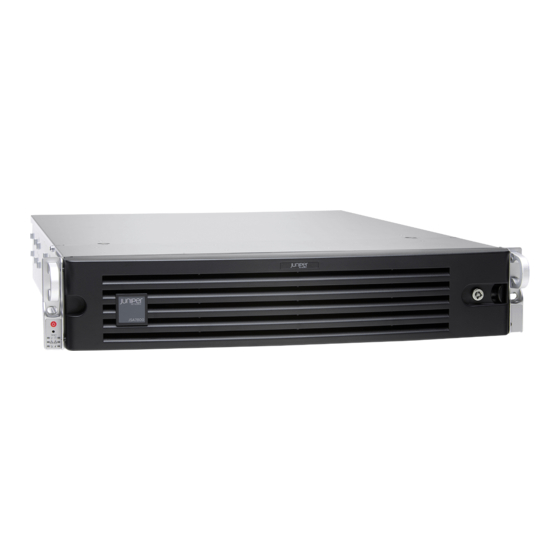
JSA7500 Back Panel | 12 JSA7500 Front Panel The JSA7500 appliance has a 2-U, rack-mountable chassis redundant DC power supplies (optional AC power supplies), twenty-eight hot-swappable hard drives in a RAID10 array, 128 GB of memory, and four Gigabit Ethernet interfaces. - Page 18 Table 4: JSA7500 Front Panel Components Callout Component Description ESD wrist strap grounding jack Connect the equipment end of your ESD grounding strap to the ESD point on the chassis to minimize the potential for electrostatic discharge (ESD) damage. Hard drives 24 drives of 900 GB HDDs (Drive0 - Drive23).
-
Page 19: Jsa7500 Back Panel
JSA7500 Back Panel Figure 2 on page 12 shows the back panel components of the JSA7500 appliance. Figure 2: JSA7500 Back Panel Table 5 on page 12 lists the back panel components of the JSA7500 appliance. Table 5: JSA7500 Back Panel Components... - Page 20 (Continued) Table 5: JSA7500 Back Panel Components Callout Component Description IOC expansion slots Two slots for additional IOC expansion with 2-port dual-rate 1GbE/10GbE SFP+ Network port 3 RJ-45 Ethernet 10/100/1000 ports USB ports Accepts a USB storage device DB-9 Serial Console port...
-
Page 21: Planning
PART Planning Site Preparation | 15... -
Page 22: Site Preparation
General Site Installation Guidelines for the JSA Appliance | 16 JSA Appliance Rack Requirements | 17 Additional Hardware Requirements Before installing your Juniper Secure Analytics (JSA) systems, ensure that you have access to the following additional hardware components: • A serial console. -
Page 23: General Site Installation Guidelines For The Jsa Appliance
DNS lookups System security updates from Juniper Networks NTP time synchronizatio RELATED DOCUMENTATION JSA Appliance Hardware Features | 3 JSA Appliance Rack Requirements | 17 General Site Installation Guidelines for the JSA Appliance | 16... -
Page 24: Jsa Appliance Rack Requirements
RELATED DOCUMENTATION Additional Hardware Requirements JSA Appliance Rack Requirements The Juniper Secure Analytics (JSA) appliance can be installed in a rack. Many types of racks are acceptable, including front-mount racks and two-post (telco) racks. Table 7 on page 17 provides the details of requirements for rack size, clearance, airflow, spacing of mounting brackets and flange holes, and connecting to the building structure. - Page 25 If your geographical area is subject to earthquakes, bolt the rack to the floor. For maximum stability, also secure the rack to ceiling brackets. RELATED DOCUMENTATION Additional Hardware Requirements | 15 Hardware Specifications | 6 General Site Installation Guidelines for the JSA Appliance | 16 Grounding the JSA7500 Appliance | 77...
-
Page 26: Safety
PART Safety General Safety and Regulatory Information | 20 Radiation and Laser Warnings | 28 Installation and Maintenance Safety Information | 33 Power and Electrical Safety Information | 47 Compliance Statements | 63... -
Page 27: General Safety And Regulatory Information
CHAPTER 5 General Safety and Regulatory Information IN THIS CHAPTER General Safety Guidelines and Warnings | 20 Definitions of Safety Warning Levels | 21 Fire Safety Requirements | 23 Qualified Personnel Warning | 24 Warning Statement for Norway and Sweden | 25 Agency Approvals for JSA | 26 General Safety Guidelines and Warnings The following guidelines help ensure your safety and protect the device from damage. -
Page 28: Definitions Of Safety Warning Levels
• Never install electrical jacks in wet locations unless the jacks are specifically designed for wet environments. • Operate the device only when it is properly grounded. • Ensure that the separate protective earthing terminal provided on this device is permanently connected to earth. - Page 29 CAUTION: You need to observe the specified guidelines to avoid minor injury or discomfort to you or severe damage to the device. LASER WARNING: This symbol alerts you to the risk of personal injury from a laser. WARNING: This symbol means danger. You are in a situation that could cause bodily injury.
-
Page 30: Fire Safety Requirements
In addition, you should establish procedures to protect your equipment in the event of a fire emergency. Juniper Networks products should be installed in an environment suitable for electronic equipment. We recommend that fire suppression equipment be available in the event of a fire in the vicinity of the equipment and that all local fire, safety, and electrical codes and ordinances be observed when you install and operate your equipment. -
Page 31: Qualified Personnel Warning
NOTE: To keep warranties effective, do not use a dry chemical fire extinguisher to control a fire at or near a Juniper Networks JSA appliance or other network device provided by Juniper. If a dry chemical fire extinguisher is used, the unit is no longer eligible for coverage under a service agreement. -
Page 32: Warning Statement For Norway And Sweden
Varoitus Ainoastaan koulutettu ja pätevä henkilökunta saa asentaa tai vaihtaa tämän laitteen. Attention Tout installation ou remplacement de l'appareil doit être réalisé par du personnel qualifié et compétent. Warnung Gerät nur von geschultem, qualifiziertem Personal installieren oder auswechseln lassen. Avvertenza Solo personale addestrato e qualificato deve essere autorizzato ad installare o sostituire questo apparecchio. -
Page 33: Agency Approvals For Jsa
Definitions of Safety Warning Levels | 21 Fire Safety Requirements | 23 Qualified Personnel Warning | 24 Agency Approvals for JSA JSA7500 comply with the following standards: • Safety • CAN/CSA-C22.2 No. 60950-1 (2007) Information Technology Equipment • UL 60950-1 (2nd Ed.) Information Technology Equipment •... - Page 34 • GR-1089-Core • Common Bonding Network(CBN) • National Electrical Code (NEC) RELATED DOCUMENTATION Compliance Statements for EMC Requirements for JSA | 63 Compliance Statements for NEBS Standards for JSA7500 | 66 Compliance Statements for Acoustic Noise for JSA | 66...
-
Page 35: Radiation And Laser Warnings
CHAPTER 6 Radiation and Laser Warnings IN THIS CHAPTER Laser and LED Safety Guidelines and Warnings for JSA | 28 Radiation from Open Port Apertures Warning | 31 Laser and LED Safety Guidelines and Warnings for JSA IN THIS SECTION General Laser Safety Guidelines | 28 Class 1 Laser Product Warning | 29 Class 1 LED Product Warning | 29... - Page 36 LASER WARNING: Unterminated optical connectors can emit invisible laser radiation. The lens in the human eye focuses all the laser power on the retina, so focusing the eye directly on a laser source—even a low-power laser—could permanently damage the eye. Class 1 Laser Product Warning LASER WARNING: Class 1 laser product.
- Page 37 Advarsel LED-produkt i klasse 1. Aviso Produto de classe 1 com LED. ¡Atención! Aviso sobre producto LED de Clase 1. Varning! Lysdiodprodukt av klass 1. Laser Beam Warning LASER WARNING: Do not stare into the laser beam or view it directly with optical instruments.
-
Page 38: Radiation From Open Port Apertures Warning
LASER WARNING: ¡Atención! No mirar fijamente el haz ni observarlo directamente con instrumentos ópticos. LASER WARNING: Varning! Rikta inte blicken in mot strålen och titta inte direkt på den genom optiska instrument. RELATED DOCUMENTATION Radiation from Open Port Apertures Warning | 31 Maintenance and Operational Safety Guidelines and Warnings | 41 Installation Instructions Warning | 33 Radiation from Open Port Apertures Warning... - Page 39 Advarsel Unngå utsettelse for stråling, og stirr ikke inn i åpninger som er åpne, fordi usynlig stråling kan emiteres fra portens åpning når det ikke er tilkoblet en fiberkabel. Aviso Dada a possibilidade de emissão de radiação invisível através do orifício da via de acesso, quando esta não tiver nenhum cabo de fibra conectado, deverá...
-
Page 40: Installation And Maintenance Safety Information
CHAPTER 7 Installation and Maintenance Safety Information IN THIS CHAPTER Installation Instructions Warning | 33 Chassis Lifting Guidelines for JSA | 34 Ramp Warning | 35 Rack-Mounting Warnings | 35 Grounded Equipment Warning | 40 Maintenance and Operational Safety Guidelines and Warnings | 41 Installation Instructions Warning WARNING: Read the installation instructions before you connect the device to a power source. -
Page 41: Chassis Lifting Guidelines For Jsa
Maintenance and Operational Safety Guidelines and Warnings | 41 Chassis Lifting Guidelines for JSA The weight of a fully loaded Juniper Secure Analytics (JSA) appliance is approximately 27 lb (12 kg). Observe the following guidelines for lifting and moving a JSA appliance: •... -
Page 42: Ramp Warning
Ramp Warning WARNING: When installing the device, do not use a ramp inclined at more than 10 degrees. Waarschuwing Gebruik een oprijplaat niet onder een hoek van meer dan 10 graden. Varoitus Älä käytä sellaista kaltevaa pintaa, jonka kaltevuus ylittää 10 astetta. Attention Ne pas utiliser une rampe dont l'inclinaison est supérieure à... - Page 43 De onderstaande richtlijnen worden verstrekt om uw veiligheid te verzekeren: • De Juniper Networks device moet in een stellage worden geïnstalleerd die aan een bouwsel is verankerd. • Dit toestel dient onderaan in het rek gemonteerd te worden als het toestel het enige in het rek is.
- Page 44 Les directives ci-dessous sont destinées à assurer la protection du personnel: • Le rack sur lequel est monté le Juniper Networks device doit être fixé à la structure du bâtiment. • Si cette unité constitue la seule unité montée en casier, elle doit être placée dans le bas.
- Page 45 As seguintes directrizes ajudá-lo-ão a efectuar o seu trabalho com segurança: • O Juniper Networks device deverá ser instalado numa prateleira fixa à estrutura do edificio. • Esta unidade deverá ser montada na parte inferior da estante, caso seja esta a única unidade a ser montada.
- Page 46 Para garantizar su seguridad, proceda según las siguientes instrucciones: • El Juniper Networks device debe instalarse en un bastidor fijado a la estructura del edificio. • Colocar el equipo en la parte inferior del bastidor, cuando sea la única unidad en el mismo.
-
Page 47: Grounded Equipment Warning
Grounded Equipment Warning WARNING: The device is intended to be grounded. During normal use, ensure that you have connected earth ground to the chassis. Waarschuwing Deze apparatuur hoort geaard te worden Zorg dat de host-computer tijdens normaal gebruik met aarde is verbonden. Varoitus Tämä... -
Page 48: Maintenance And Operational Safety Guidelines And Warnings
Maintenance and Operational Safety Guidelines and Warnings IN THIS SECTION Battery Handling Warning | 41 Jewelry Removal Warning | 42 Lightning Activity Warning | 43 Operating Temperature Warning | 44 Product Disposal Warning | 45 While performing the maintenance activities for devices, observe the following guidelines and warnings: Battery Handling Warning WARNING: Replacing a battery incorrectly might result in an explosion. - Page 49 Advarsel Det kan være fare for eksplosjon hvis batteriet skiftes på feil måte. Skift kun med samme eller tilsvarende type som er anbefalt av produsenten. Kasser brukte batterier i henhold til produsentens instruksjoner. Avvertenza Pericolo di esplosione se la batteria non è installata correttamente. Sostituire solo con una di tipo uguale o equivalente, consigliata dal produttore.
- Page 50 Warnung Vor der Arbeit an Geräten, die an das Netz angeschlossen sind, jeglichen Schmuck (einschließlich Ringe, Ketten und Uhren) abnehmen. Metallgegenstände erhitzen sich, wenn sie an das Netz und die Erde angeschlossen werden, und können schwere Verbrennungen verursachen oder an die Anschlußklemmen angeschweißt werden.
- Page 51 WARNING: To prevent the device from overheating, do not operate it in an area that exceeds the maximum recommended ambient temperature of 104° F (40° C) for network devices of Juniper Networks. To prevent airflow restriction, allow at least 6 in. (15.2 cm) of clearance around the ventilation openings.
- Page 52 40° C. Para evitar a restrição à circulação de ar, deixe pelo menos um espaço de 15,2 cm à volta das aberturas de ventilação. ¡Atención! Para impedir que un encaminador de la serie Juniper Networks device se recaliente, no lo haga funcionar en un área en la que se supere la temperatura ambiente máxima recomendada de 40°...
- Page 53 Attention La mise au rebut définitive de ce produit doit être effectuée conformément à toutes les lois et réglementations en vigueur. Warnung Dieses Produkt muß den geltenden Gesetzen und Vorschriften entsprechend entsorgt werden. Avvertenza L'eliminazione finale di questo prodotto deve essere eseguita osservando le normative italiane vigenti in materia Advarsel Endelig disponering av dette produktet må...
-
Page 54: Power And Electrical Safety Information
CHAPTER 8 Power and Electrical Safety Information IN THIS CHAPTER General Electrical Safety Guidelines and Warnings | 47 Prevention of Electrostatic Discharge Damage | 49 AC Power Electrical Safety Guidelines | 51 AC Power Disconnection Warning | 52 DC Power Electrical Safety Guidelines | 53 DC Power Disconnection Warning | 54 DC Power Grounding Requirements and Warning | 56 DC Power Wiring Sequence Warning | 57... - Page 55 WARNING: The intrabuilding port(s) (40G DACS and USB ports) of the equipment or subassembly must use shielded intrabuilding cabling or wiring that is grounded at both ends. WARNING: The intrabuilding port(s) (including the following ports, when present: DAC, External Clock, Internal Clock, T1/E1, POE Ethernet) of the equipment or subassembly must use shielded intrabuilding cabling or wiring that is grounded at both ends.
-
Page 56: Prevention Of Electrostatic Discharge Damage
You can remove and replace many device components without powering off or disconnecting power to the device, as detailed elsewhere in the hardware documentation for this device. Never install an equipment that it appears to be damaged. RELATED DOCUMENTATION Prevention of Electrostatic Discharge Damage | 49 Multiple Power Supplies Disconnection Warning | 60 TN Power Warning | 61 Action to Take After an Electrical Accident | 61... - Page 57 • When removing or installing a component that is subject to ESD damage, always place it component- side up on an antistatic surface, in an antistatic card rack, or in an antistatic bag (see Figure 3 on page 50). If you are returning a component, place it in an antistatic bag before packing it. Figure 3: Placing a Component into an Antistatic Bag CAUTION: ANSI/TIA/EIA-568 cables such as Category 5e and Category 6 can get electrostatically charged.
-
Page 58: Ac Power Electrical Safety Guidelines
AC Power Electrical Safety Guidelines CAUTION: For devices with AC power supplies, an external surge protective device (SPD) must be used at the AC power source. The following electrical safety guidelines apply to AC-powered devices: • Note the following warnings printed on the device: “CAUTION: THIS UNIT HAS MORE THAN ONE POWER SUPPLY CORD. -
Page 59: Ac Power Disconnection Warning
RELATED DOCUMENTATION General Electrical Safety Guidelines and Warnings | 47 Prevention of Electrostatic Discharge Damage | 49 AC Power Disconnection Warning | 52 DC Power Electrical Safety Guidelines | 53 DC Power Disconnection Warning | 54 AC Power Disconnection Warning WARNING: Before working on the device or near power supplies, unplug all the power cords from the appliance. -
Page 60: Dc Power Electrical Safety Guidelines
RELATED DOCUMENTATION General Electrical Safety Guidelines and Warnings | 47 Prevention of Electrostatic Discharge Damage | 49 AC Power Electrical Safety Guidelines | 51 DC Power Electrical Safety Guidelines | 53 DC Power Electrical Safety Guidelines • A DC-powered device is equipped with a DC terminal block that is rated for the power requirements of a maximally configured device. -
Page 61: Dc Power Disconnection Warning
• The marked input voltage of –38 VDC for a DC-powered device is the nominal voltage associated with the battery circuit, and any higher voltages are only to be associated with float voltages for the charging function. • Because the device is a positive ground system, you must connect the positive lead to the terminal labeled RTN, the negative lead to the terminal labeled –38 VDC, and the earth ground to the device grounding points. - Page 62 disjoncteur en position fermée (OFF) et, à l'aide d'un ruban adhésif, bloquer la poignée du disjoncteur en position OFF. Warnung Vor Ausführung der folgenden Vorgänge ist sicherzustellen, daß die Gleichstromschaltung keinen Strom erhält. Um sicherzustellen, daß sämtlicher Strom abgestellt ist, machen Sie auf der Schalttafel den Unterbrecher für die Gleichstromschaltung ausfindig, stellen Sie den Unterbrecher auf AUS, und kleben Sie den Schaltergriff des Unterbrechers mit Klebeband in der AUS-Stellung fest.
-
Page 63: Dc Power Grounding Requirements And Warning
AC Power Electrical Safety Guidelines | 51 DC Power Electrical Safety Guidelines | 53 DC Power Grounding Requirements and Warning | 56 DC Power Wiring Sequence Warning | 57 DC Power Grounding Requirements and Warning An insulated grounding conductor that is identical in size to the grounded and ungrounded branch circuit supply conductors but is identifiable by green and yellow stripes is installed as part of the branch circuit that supplies the device. -
Page 64: Dc Power Wiring Sequence Warning
RELATED DOCUMENTATION General Electrical Safety Guidelines and Warnings | 47 Prevention of Electrostatic Discharge Damage | 49 AC Power Electrical Safety Guidelines | 51 AC Power Disconnection Warning | 52 DC Power Electrical Safety Guidelines | 53 DC Power Disconnection Warning | 54 DC Power Wiring Sequence Warning WARNING: Wire the DC power supply using the appropriate lugs. - Page 65 Avvertenza Mostra la morsettiera dell alimentatore CC. Cablare l'alimentatore CC usando i connettori adatti all'estremità del cablaggio, come illustrato. La corretta sequenza di cablaggio è da massa a massa, da positivo a positivo (da linea ad L) e da negativo a negativo (da neutro a N). Tenere presente che il filo di massa deve sempre venire collegato per primo e scollegato per ultimo.
-
Page 66: Dc Power Wiring Terminations Warning
DC Power Wiring Terminations Warning WARNING: When stranded wiring is required, use approved wiring terminations, such as closed-loop or spade-type with upturned lugs. These terminations must be the appropriate size for the wires and must clamp both the insulation and conductor. Waarschuwing Wanneer geslagen bedrading vereist is, dient u bedrading te gebruiken die voorzien is van goedgekeurde aansluitingspunten, zoals het gesloten-lus type of het grijperschop type waarbij de aansluitpunten omhoog wijzen. -
Page 67: Multiple Power Supplies Disconnection Warning
¡Atención! Cuando se necesite hilo trenzado, utilizar terminales para cables homologados, tales como las de tipo "bucle cerrado" o "espada", con las lengüetas de conexión vueltas hacia arriba. Estos terminales deberán ser del tamaño apropiado para los cables que se utilicen, y tendrán que sujetar tanto el aislante como el conductor. Varning! När flertrådiga ledningar krävs måste godkända ledningskontakter användas, t.ex. -
Page 68: Tn Power Warning
TN Power Warning WARNING: The device is designed to work with a TN power system. Waarschuwing Het apparaat is ontworpen om te functioneren met TN energiesystemen. Varoitus Koje on suunniteltu toimimaan TN-sähkövoimajärjestelmien yhteydessä. Attention Ce dispositif a été conçu pour fonctionner avec des systèmes d'alimentation Warnung Das Gerät ist für die Verwendung mit TN-Stromsystemen ausgelegt. - Page 69 RELATED DOCUMENTATION General Electrical Safety Guidelines and Warnings | 47 Prevention of Electrostatic Discharge Damage | 49 Multiple Power Supplies Disconnection Warning | 60 TN Power Warning | 61...
-
Page 70: Compliance Statements
Korea | 65 United States | 65 FCC Part 15 Statement | 65 This topic describes the EMC requirements for the Juniper Secure Analytics (JSA) appliances: Canada This Class A digital apparatus complies with Canadian ICES-003. Cet appareil numérique de la classe A est conforme à la norme NMB-003 du Canada. - Page 71 Before installing this equipment, users should ensure that it is permissible to connect the equipment to the facilities of the local telecommunications company. The equipment must also be installed using an acceptable method of connection. In some cases, the inside wiring associated with a single line individual service can be extended by means of a certified connector assembly.
- Page 72 Korea The preceding translates as follows: This equipment is Industrial (Class A) electromagnetic wave suitability equipment and seller or user should take notice of it, and this equipment is to be used in the places except for home United States The device has been tested and found to comply with the limits for a Class A digital device, pursuant to Part 15 of the FCC Rules.
-
Page 73: Compliance Statements For Acoustic Noise For Jsa
Installation Instructions Warning | 33 Compliance Statements for Acoustic Noise for JSA This topic applies to JSA7500 in the Juniper Secure Analytics (JSA) product family. Maschinenlärminformations-Verordnung - 3. GPSGV, der höchste Schalldruckpegel beträgt 70 dB(A) oder weniger gemäss EN ISO 7779 Translation: The emitted sound pressure is below 70 dB(A) per EN ISO 7779. - Page 74 WARNING: The intrabuilding port(s) (40G DACS and USB ports) of the equipment or subassembly must use shielded intrabuilding cabling/wiring that is grounded at both ends. RELATED DOCUMENTATION Compliance Statements for Acoustic Noise for JSA | 66 Compliance Statements for EMC Requirements for JSA | 63 Agency Approvals for JSA | 26...
-
Page 75: Installation
PART Installation Hardware Installation Overview | 69 Software Installation Overview | 71 Connecting the JSA Appliance | 77 Installing the JSA Appliance | 83 Configuring Basic Settings | 96 Configuring Secure Web Access | 99... -
Page 76: Hardware Installation Overview
"Front-and-Rear-Mounting the JSA Appliance Recessed in a Rack" on page 87 • "Mid-Mounting the JSA Appliance in a Two-Post Rack" on page 92 The following rack type is supported for the Juniper Secure Analytics (JSA) appliance: • 19-in. 4-post rack • 19-in. 2-post rack... - Page 77 Table 8: Required Tools and Parts for Installing the JSA Appliance Task Tools and Parts Installing the JSA Appliance • Phillips (+) screwdriver, number 1 • Phillips (+) screwdriver, number 3 • Tie wrap Connecting the JSA Appliance ESD grounding wrist strap Grounding the JSA Appliance Phillips (+) screwdriver, number 1 Packing the JSA Appliance...
-
Page 78: Software Installation Overview
JSA Components Juniper Secure Analytics (JSA) includes the following deployment components: NOTE: When deploying a Juniper Secure Analytics (JSA) appliance with image 2013.2.r3.607582, you must reimage the appliance to the common image 2013.2.r3.615469 or Installing JSA Using a Bootable USB Flash-Drive Technical above. - Page 79 • Event Collector—Collects security events from various types of security devices, known as log sources, in your network. The Event Collector gathers events from local and remote log sources. The Event Collector then normalizes the events and sends the information to the Event Processor. The Event Collector also bundles all virtually identical events to conserve system usage.
-
Page 80: Browser Support
Identifying Network Assets | 97 Browser Support To access the Juniper Secure Analytics (JSA) interface, you must have a Web browser installed on your client system. JSA supports the following browsers: • Microsoft® Windows Internet Explorer, with Compatibility View Enabled - 8.0 and 9.0 •... - Page 81 For more information, see the The following sections explain how to set your network before you install the JSA software: Identifying Network Settings Before you install Juniper Secure Analytics (JSA), you must have the following information for each system you want to install:...
- Page 82 • NTP server (Console only) or Time server Identifying Security Monitoring Devices and Flow Data Sources Juniper Secure Analytics (JSA) can collect and correlate events received from external sources such as security equipment (for example, firewalls, VPNs, or IDSs) and host or application security logs, such as Windows logs.
- Page 83 Defining certain additional server and IP address types also improves tuning results. Table 10 on page Juniper Secure Analytics Users Guide for information on provides a list of possible servers. See the defining servers within JSA. If your network includes a large number of servers, you can use CIDR or IP subnet addresses within the server networks category.
-
Page 84: Connecting The Jsa Appliance
JSA7500 appliance before connecting it to the power source. You can ground the JSA7500 appliance either from the side of the chassis or from the rear panel. If you use the grounding lug, then we recommend that you use the grounding points available on the side of the chassis. - Page 85 (Continued) Table 11: Grounding Cable and Grounding Lug Specifications for the JSA7500 Appliance Grounding Requirement Specification Amperage of grounding cable Up to 50 A Grounding kit Two 10-32 x 1/4-in. pan-head screws with two 1 mm washers and one grounding lug The grounding kit is shipped with the JSA7500 appliance.
- Page 86 4. Secure the grounding cable lug to the grounding points with the screws and washers as shown in Figure 4 on page 5. Dress the grounding cable, and verify that it does not touch or block access to the JSA7500 components and that it does not cause a tripping hazard.
-
Page 87: Connecting Jsa7500 To A Dc Power Source
Connecting JSA7500 to a DC Power Source Before connecting your Juniper Secure Analytics (JSA) appliance to a DC power source: • Ensure that you have taken the necessary precautions to prevent ESD damage. • Ensure that you have connected the JSA appliance chassis to earth ground. - Page 88 NOTE: The red cable should be connected to the V+ terminal, and the black cable should be connected to the V- terminal, respectively, as shown in Figure 5 on page 4. Attach the plastic safety cover. RELATED DOCUMENTATION Connecting to a Management Device | 82 Installing the CNA Module on the JSA7500 Appliance | 94...
-
Page 89: Connecting To A Management Device
Grounding the JSA7500 Appliance | 77 Connecting to a Management Device You can control the Juniper Secure Analytics (JSA) appliance through a connected management device (such as a desktop or laptop). Use the RJ-45 serial port and console port to connect your laptop and desktop respectively. -
Page 90: Installing The Jsa Appliance
Front-and-Rear-Mounting the JSA Appliance Flush to a Rack | 86 Front-and-Rear-Mounting the JSA Appliance Recessed in a Rack | 87 Front-and-Rear-Mounting the JSA7500 in a 4-Post Sliding Rail Rack | 88 Mid-Mounting the JSA Appliance in a Two-Post Rack | 92... - Page 91 2. Plug the power cord into the AC receptacle on the rear panel. See Figure 6 on page 84. If your JSA contains two power supplies, plug a power cord into each of the AC receptacles. Figure 6: JSA7500 Back Panel Hard drive USB ports —...
- Page 92 JSA hard disk. RELATED DOCUMENTATION Connecting to a Management Device | 82 Installing the CNA Module on the JSA7500 Appliance | 94 Grounding the JSA7500 Appliance | 77 Connecting JSA7500 to a DC Power Source | 80...
-
Page 93: Front-And-Rear-Mounting The Jsa Appliance Flush To A Rack
Front-and-Rear-Mounting the JSA Appliance Flush to a Rack This option is used for larger chassis that require additional support when mounted on the rack-mount system. The JSA7500 appliance use this mounting option as its default configuration. To mount JSA7500 using this option: 1. -
Page 94: Front-And-Rear-Mounting The Jsa Appliance Recessed In A Rack
Front-and-Rear-Mounting the JSA Appliance Recessed in a Rack This option provides additional front clearance in the equipment rack. It is used for a larger chassis, like the JSA7500 appliance, that requires additional support when mounted on the rack-mount system. To mount the appliance using this option: 1. -
Page 95: Front-And-Rear-Mounting The Jsa7500 In A 4-Post Sliding Rail Rack
This option is used for the chassis that can easily pulled out from the rack when mounted on the rack- mount system. The JSA7500 appliance is mounted using this option because of the fan door available on the top of the appliance. - Page 96 2. On the slide assembly, press the button on each slide and pull the glide completely out of the slide as shown in Figure 11 on page Figure 11: Slide Assembly Glide Slide — — Button — 3. Attach the glide to the sides of the appliance as shown in Figure 10 on page...
- Page 97 4. Attach the slide sets to the desired position of front and rear of the rack cabinet as shown in Figure 12 on page Figure 12: Attaching the Slide Sets...
- Page 98 5. Push the slide buttons and slide the appliance all the way into the rack enclosure as shown in Figure 13 on page Figure 13: Sliding the Appliance into the Rack...
-
Page 99: Mid-Mounting The Jsa Appliance In A Two-Post Rack
6. Secure the front-mount rail brackets to your equipment rack with two rack mount screws each as shown in Figure 14 on page Figure 14: Securing the Front-Mount Rail Brackets RELATED DOCUMENTATION Rack-Mount Installation Overview | 69 Mid-Mounting the JSA Appliance in a Two-Post Rack | 92 Required Tools and Parts for Installing the JSA Appliance | 69 Mid-Mounting the JSA Appliance in a Two-Post Rack This option is suitable for a two-post equipment rack. - Page 100 To mount the appliance using this option: 1. Remove the two front-mount rails from either side of the chassis. 2. Insert one mid-mount bracket to the center on either side of the chassis. 3. Attach the chassis to the equipment rack and insert the other two mid-mount brackets on either side of the system to secure the chassis to the backs of the post.
-
Page 101: Installing The Cna Module On The Jsa7500 Appliance
• The IOC module supports 10G connectivity with SFP+ transceivers. It supports only 1G connectivity using dual-rate optics: UNIV-SFPP-DUAL-SR and UNIV-SFPP-DUAL-LR. • The JSA7500 supports only the 2-port 10G IOC module in a one-half height tray. 3. Insert the 2-port 10G IOC module firmly and screw in the two thumbscrews. See... - Page 102 • 1 = eth1 • 2 = eth2 • 3 = eth3 RELATED DOCUMENTATION Connecting to a Management Device | 82 Grounding the JSA7500 Appliance | 77 Connecting JSA7500 to a DC Power Source | 80 Installing the JSA Hardware | 83...
-
Page 103: Configuring Basic Settings
Identifying Network Assets | 97 Identifying Network Settings Before you install Juniper Secure Analytics (JSA), you must have the following information for each system you want to install: NOTE: When you configure the network setting such as hostname and IP address using the qchange_netsetup script, the JSA appliance hangs while rebooting. -
Page 104: Identifying Security Monitoring Devices And Flow Data Sources | 97
Identifying Network Assets | 97 Identifying Security Monitoring Devices and Flow Data Sources Juniper Secure Analytics (JSA) can collect and correlate events received from external sources such as security equipment (for example, firewalls, VPNs, or IDSs) and host or application security logs, such as Windows logs. - Page 105 Defining certain additional server and IP address types also improves tuning results. Table 12 on page Users Guide for information on defining servers within provides a list of possible servers. See the JSA. If your network includes a large number of servers, you can use CIDR or IP subnet addresses within the server networks category.
-
Page 106: Configuring Secure Web Access
Configuring the Basic Settings | 99 Accessing the JSA Interface | 102 Configuring the Basic Settings NOTE: When deploying a Juniper Secure Analytics (JSA) appliance with image 2013.2.r3.607582, you must reimage the appliance to the common image 2013.2.r3.615469 or above. For more information, see Installing JSA Using a Bootable USB Flash-Drive Technical Note. - Page 107 Use left or right arrow keys to select Next. Select the appliance ID and then press Enter to select Next. For more information on the appliance ID, see the KB article KB14832 at https:/ /kb.juniper.net/ KB14832. Select normal from the following types of setup: normal —Default setup...
- Page 108 18. To configure the JSA network settings, enter the values for the following parameters. Use the up or down arrow keys to navigate the fields: NOTE: When you configure the network setting such as hostname and IP address using the qchange_netsetup script, the JSA appliance hangs while rebooting.
-
Page 109: Accessing The Jsa Interface
Accessing the JSA Interface IN THIS SECTION Purpose | 102 Action | 102 Purpose To access a Juniper Secure Analytics (JSA) interface: Action 1. Open your Web browser. 2. Log in to JSA: https:/ /<IP Address> <IP Address> is the IP address of the JSA system. - Page 110 The JSA interface appears. You are now ready to start tuning JSA and high availability (HA) settings. Juniper Secure Analytics Administration Guide . For more information, see the NOTE: You will need a permanent license for the JSA appliance to upgrade to a higher version. If you have a temporary license, the upgrade will fail;...
-
Page 111: Maintenance
PART Maintenance Maintaining the Hardware | 105... -
Page 112: Maintaining The Hardware
Replacing DC Power Supply Cables on the JSA Appliance | 113 Field-Replaceable Units on the JSA Appliance Field-replaceable units (FRUs) are Juniper Secure Analytics (JSA) hardware components that can be replaced at the customer site. Hot-swappable FRUs are the components that you can remove and replace without powering off the device or disrupting the functions of the device. -
Page 113: Replacing The Fan On The Jsa Appliance
Replacing the Fan on the JSA Appliance The JSA7500 has eight cooling fans. The fans are hot-swappable. NOTE: • JSA7500 has internal hot-swappable cooling fans. These cooling fans are removed and installed from the top of the JSA7500. To remove and install the fan for JSA7500: Attach an ESD grounding strap to your bare wrist and connect the strap to the ESD point on the chassis. - Page 114 Turn the screws to the left on the fan door at the top of the device as shown in Figure 17 on page 107. Figure 17: Opening the Chassis Lid Open the lid as shown in Figure 17 on page 107.
- Page 115 Grasp the fan protected with the cover and pull it out to disengage its power connection as shown Figure 18 on page 108. Figure 18: Removing the Fan Wait for the fan to stop spinning. WARNING: To avoid injury, do not proceed until the fan has stopped spinning.
-
Page 116: Replacing The Air Filter On The Jsa7500 Appliance
Replacing a DC Power Supply on the JSA Appliance | 112 Replacing DC Power Supply Cables on the JSA Appliance | 113 Replacing the Air Filter on the JSA7500 Appliance The JSA7500 ships with a front bezel with air filter to provide optimum cooling to the appliance. -
Page 117: Replacing An Ac Power Supply On The Jsa Appliance
CAUTION: Always keep the air filter in place while the JSA7500 appliance is operating. Running the appliance without the air filter in place could cause of small bits of dirt or other materials could be blown into the appliance. This could damage the appliance components. -
Page 118: Replacing Ac Power Supply Cables On The Jsa Appliance
Field-Replaceable Units on the JSA Appliance | 105 Replacing the Fan on the JSA Appliance | 106 Replacing the Air Filter on the JSA7500 Appliance | 109 Replacing AC Power Supply Cables on the JSA Appliance | 111 Replacing a DC Power Supply on the JSA Appliance | 112... -
Page 119: Replacing A Dc Power Supply On The Jsa Appliance
Replacing the Air Filter on the JSA7500 Appliance | 109 Replacing an AC Power Supply on the JSA Appliance | 110 Replacing a DC Power Supply on the JSA Appliance | 112 Replacing DC Power Supply Cables on the JSA Appliance | 113... -
Page 120: Replacing Dc Power Supply Cables On The Jsa Appliance
Field-Replaceable Units on the JSA Appliance | 105 Replacing the Fan on the JSA Appliance | 106 Replacing the Air Filter on the JSA7500 Appliance | 109 Replacing an AC Power Supply on the JSA Appliance | 110 Replacing AC Power Supply Cables on the JSA Appliance | 111... -
Page 121: Troubleshooting
PART Troubleshooting Monitoring Hardware Components | 115 Juniper Networks Technical Assistance Center | 119 Knowledge Base | 120... -
Page 122: Monitoring Hardware Components
• Striping—split data across more than one disk • Error correction—redundant data storage to detect and resolve problems JSA7500 uses RAID10. RAID1 uses mirroring and duplex techniques to copy data to the redundant disk. In RAID10, drives are duplicated for fault tolerance. -
Page 123: Power Supply
JSA7500 Front Panel | 10 JSA7500 Back Panel | 12 Power Supply The JSA7500 appliance ships with redundant DC power supplies and also supports AC power supply option if you need AC power. To maintain the power supplies, follow these guidelines: •... -
Page 124: Cooling Fans
JSA7500 Front Panel | 10 Maintaining the JSA7500 Air Filter The JSA7500 ships with a front bezel with air filter to provide optimum cooling to the appliance. For optimum cooling, maintain the air filter, as follows: • Regularly inspect the air filter. - Page 125 • Use spare filters within the period defined by the manufacturer. Check the date of manufacture printed on the filter. Store spare air filters in a dark, cool, and dry place. Storing air filters at higher temperatures, or where they can be exposed to ultraviolet (UV) radiation, hydrocarbon emissions, or vapors from solvents, can significantly reduce their life.
-
Page 126: Juniper Networks Technical Assistance Center
Contacting Juniper Networks Technical Assistance Center If you need assistance while troubleshooting a JSA appliance, open a support case using the Case Manager link at https:/ /www.juniper.net/support/, or call 1-888-314-JTAC (within the United States) or 1-408-745-9500 (from outside the United States). -
Page 127: Knowledge Base
CHAPTER 19 Knowledge Base...