Table of Contents
Advertisement
SECTION I-MAINTENANCE
SUBJECT
1.
Specifications . . . . . . . . . . . . . . . . . . . . . . . . . . . . . . . . . . . . . . . . . . . . . . . . . . . . . . . . . . . 3
2.
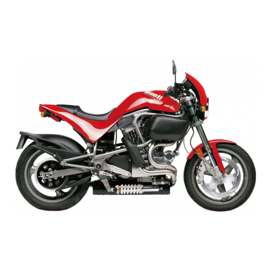
Side Views. . . . . . . . . . . . . . . . . . . . . . . . . . . . . . . . . . . . . . . . . . . . . . . . . . . . . . . . . . . . . . 4
3.
Fluid Requirements . . . . . . . . . . . . . . . . . . . . . . . . . . . . . . . . . . . . . . . . . . . . . . . . . . . . . . . 6
4.
Clutch . . . . . . . . . . . . . . . . . . . . . . . . . . . . . . . . . . . . . . . . . . . . . . . . . . . . . . . . . . . . . . . . . 7
5.
Rear Preload Adjustment . . . . . . . . . . . . . . . . . . . . . . . . . . . . . . . . . . . . . . . . . . . . . . . . . . 8
6.
Ignition Timing . . . . . . . . . . . . . . . . . . . . . . . . . . . . . . . . . . . . . . . . . . . . . . . . . . . . . . . . . . . 9
This section explains procedures unique to 1997 model S1 Lightnings. Any procedures not found
in this supplement are covered in the
1996 S1 Lightning Service Manual
PAGE NO.
(Part No. 99490-96Y).
1
Advertisement
Chapters
Table of Contents

Related Manuals for Buell S1 Lightning


Summary of Contents for Buell S1 Lightning
-
Page 1: Table Of Contents
Ignition Timing ............9 This section explains procedures unique to 1997 model S1 Lightnings. Any procedures not found in this supplement are covered in the 1996 S1 Lightning Service Manual (Part No. 99490-96Y). - Page 2 NOTES...
-
Page 3: Specifications
SPECIFICATIONS DIMENSIONS IGNITION SYSTEM Wheel base 1397 Spark plugs No. 6R12 Overall length 79.5 2019 Size 12 mm Overall width 0.038-0.045 in. 0.97-1.14 mm Road clearance Seat height 29.5 TRANSMISSION Type Constant Mesh, Foot Shift Speeds 5 Forward CAPACITIES U.S. LITERS Fuel tank (including reserve) 4.0 gallons... -
Page 4: Side Views
11. Battery drive belt Front brake master cylinder 12. Voltage regulator Ignition module Front brake hand lever 13. Rider footrest Fuse block and spare fuse Front brake caliper 14. Passenger footrest Figure 2. 1997 S1 Lightning, Right Side View (Body Removed) - Page 5 12. Gear shift lever Clutch hand lever Oil tank 13. Exhaust muffler Ignition coil Rear brake caliper 14. Oil filter Enrichener knob 10. Rear axle adjuster nut 15. Speedometer drive Figure 4. 1997 S1 Lightning, Left Side View (Body Removed)
-
Page 6: Fluid Requirements
FLUID REQUIREMENTS GENERAL FRONT FORK OIL Use only WP FORK OIL, 5 WEIGHT. United States System FUEL Unless otherwise specified, all fluid volume measurements in this Service Manual are expressed in United States Use a good quality leaded or unleaded gasoline (91 pump (U.S.) units-of-measure. -
Page 7: Clutch
CLUTCH MODEL YEAR CHANGE 5671 Figure 5. All 1997 model year motorcycles use the new New style Old style style clutch release ramp introduced on late 1996 vehicles. The clutch adjustment and lever freeplay procedures remain the same. The change was made to provide additional clear- ance between the coupler and the primary cover. -
Page 8: Rear Preload Adjustment
Spring preload is the most important suspension adjustment on the S1 Lightning. Improper preload will adversely affect both the handling and motorcycle ride. Correct preload set- ting will result in motorcycle handling that suits the rider’s size and weight. -
Page 9: Ignition Timing
IGNITION TIMING MODEL YEAR CHANGE 5853 Figure 8. All 1997 model year motorcycles have the remote idle adjuster introduced on late 1996 vehicles. Using this adjuster, it is no longer necessary to use the CARBURE- TOR IDLE ADJUSTMENT TOOL (Part No. HD-33413) TIP (SNAP-ON Part No. - Page 10 NOTES...
- Page 11 Swingarm ............. . 16 This section explains procedures unique to 1997 model S1 Lightnings. Any procedures not found in this supplement are covered in the 1996 S1 Lightning Service Manual (Part No. 99490-96Y).
- Page 12 NOTES...
-
Page 13: Vehicle Identification Number
Number (V.I.N.), is stamped on the right side of the steer- Always give the V.I.N. or abbreviated V.I.N. when ordering ing head (ex., 4MZSS11J1V3200001). Also affixed to the parts or making inquiries about your Buell motorcycle. steering head at this location is an information decal bearing the V.I.N. code. -
Page 14: Front Wheel
FRONT WHEEL MODEL YEAR CHANGE 5874 Figure 10. All 1997 model year motorcycles have new fasteners on the front brake rotor/carrier assembly. Separate the carrier from the rotor only when necessary. Use new clips when reassembling. NOTE The new rotor/carrier assembly changes Step 4 of FRONT WHEEL, REMOVAL and Step 2 of... -
Page 15: Front Brake Caliper
FRONT BRAKE CALIPER TOOL INFORMATION b0265x2x Use the BRAKE CALIPER PISTON REMOVER (Part No. B- 42079) to simplify front caliper piston removal. Banjo bolt hole NOTE The following instructions expand upon Step 9 of FRONT BRAKE CALIPER, REMOVAL/DISASSEMBLY in the 1996 manual. -
Page 16: Swingarm
SWINGARM MODEL YEAR CHANGE b0290a2x All 1997 model year motorcycles use a revised swingarm Threads pivot assembly. The modifications allow preload to be adjusted without using the PIVOT SHAFT BEARING ADJUSTER (Part No. B-41175). NOTE Figure 14. The threaded rod (1) replaces a pivot shaft used on 1996 models. - Page 17 SECTION III–ENGINE All engine procedures in the 1996 S1 Lightning Service Manual (Part No. 99490-96Y) apply to 1997 models.
- Page 18 NOTES...
- Page 19 Air Cleaner ............. 22 This section explains procedures unique to 1997 model S1 Lightnings. Any procedures not found in this supplement are covered in the 1996 S1 Lightning Service Manual (Part No. 99490-96Y).
- Page 20 NOTES...
- Page 21 REMOTE IDLE ADJUSTER GENERAL b0291xox Figure 16. The remote idle adjuster allows idle adjust- Increase ments without use of tools. Idle speeds are listed in Table 2. idle speed REMOVAL Remove seat and fuel tank. See FUEL TANK, REMOVAL in Section 4 of the 1996 manual. Adjuster Remove cable strap holding adjuster to frame.
- Page 22 AIR CLEANER MODEL YEAR CHANGE 5705 All 1997 model year motorcycles use a modified air cleaner assembly. The new design increases serviceability. REMOVAL CAUTION Do not run engine without filter element in place. Debris could be drawn into the engine causing damage. Figure 19.
- Page 23 INSTALLATION 5884 Install backplate. Apply HYLOMAR to threads of breather bolts. Install air cleaner support ring and backplate using breather bolts. Tighten breather bolts to 10-15 ft-lbs (13.6-20.3 Nm). Attach rear breather hose to rear breather bolt. Figure 24. Install two bolts (1), washers (2) and nuts (3) through backplate into isolator mount.
- Page 24 NOTES...
- Page 25 Starting System Diagnosis ..........27 This section explains procedures unique to 1997 model S1 Lightnings. Any procedures not found in this supplement are covered in the 1996 S1 Lightning Service Manual (Part No. 99490-96Y).
- Page 26 NOTES...
-
Page 27: Starting System Diagnosis
STARTING SYSTEM DIAGNOSIS — BATTERY TESTS — VISUAL VOLTAGE LOAD Check Connections at Battery and Starter Components. Continued on Next Page Solenoid Clicks. INOPERATIVE Nothing Clicks. Relay Clicks. Perform Voltage Drop Tests Between Battery and Test for Voltage at “Relay” Terminal on Solenoid Terminal. - Page 28 Continued from Previous Page STARTER SPINS, BUT RUN-ON DOES NOT ENGAGE Disconnect Solenoid “Relay” Terminal from Solenoid. Is 12V Present at GN Wire Terminal with Remove Starter. Starter Button NOT Disassemble Drive Pressed? Housing Assembly. Inspect for Damage to Armature Gear or Idler Gear.
- Page 29 SECTION VI–DRIVE/TRANSMISSION All drive/transmission procedures in the 1996 S1 Lightning Service Manual (Part No. 99490-96Y) apply to 1997 models.
- Page 30 NOTES...
- Page 31 Wiring Harness ............37 This section explains procedures unique to 1997 model S1 Lightnings. Any procedures not found in this supplement are covered in the 1996 S1 Lightning Service Manual (Part No. 99490-96Y).
- Page 32 NOTES...
-
Page 33: Handlebar Switches
HANDLEBAR SWITCHES MODEL YEAR CHANGE b0279x7x All 1997 model year motorcycles use new handlebar switches. The switches feature new icons, connectors and a different pin numbering sequence. Ignition ON NOTE HANDLEBAR SWITCHES, REMOVAL HANDLEBAR Ignition OFF SWITCHES, INSTALLATION procedures remain the same. The new switch assemblies are interchangeable between 1996 and 1997 models if the corresponding connector on the Electric starter... -
Page 34: Starter Interlock System
STARTER INTERLOCK SYSTEM INSPECTION NOTE STARTER CIRCUIT IGNITION CIRCUIT tests The starter interlock system is designed to prevent unin- should be performed in one continuous operation. Conduct tended start-up and/or forward motion of the motorcycle with both tests one after the other in the sequence given without the vehicle’s side stand not retracted. - Page 35 Ignition Circuit Remove W/BK wire from ignition coil. Connect a test light or voltmeter to the vehicle. Attach one end to W/BK wire terminal. Attach the other end to vehicle ground. Turn ignition switch to IGN. Set engine stop switch to RUN. Place motorcycle in neutral.
-
Page 36: Horn
HORN MODEL YEAR CHANGE 5882 Figure 27. All 1997 model year motorcycles have a new horn in a new location. NOTE For troubleshooting information, see HORN, TROUBLE- SHOOTING in Section 7 in the 1996 manual. REMOVAL Remove seat and fuel tank. See FUEL TANK, REMOVAL in Section 4 of the 1996 manual. -
Page 37: Wiring Harness
WIRING HARNESS MODEL YEAR CHANGE The following changes were made to the wiring harness for 1997 model year motorcycles. New connectors and a different pin numbering sequence for the right handlebar switch [P1] and the left handlebar switch [P6]. See HANDLEBAR SWITCHES page Longer wires leading to the horn to accommodate the... - Page 38 R/BK NO CONNECTION GY/O KEY SWITCH ACCESSORIES GREEN YELLOW R/GY CONNECTION PIN CONNECTOR STARTER RELAY IGNITION RELAY R GY CABLE COLOR STRIPE COLOR SOCKET CONNECTOR FUSE BLOCK LOCK BATTERY STATOR 1997 BUELL WIRING DIAGRAM 6/10/96 Figure 29. 1997 Wiring Diagram...
- Page 39 First, it will acquaint the user with the Gasoline is extremely flammable and highly explosive. construction of the 1997 Buell S1 Lightning and assist in the Always stop the engine when refueling or servicing the performance of basic maintenance and repair. Secondly, it fuel system.
- Page 40 fly outward with considerable force, obligation. possibly resulting in personal injury. Buell products are manufactured under one or more of the following patents: U.S. Patents – 2986161, 2987934, 2998809, 3116089, 3144531, 3144860, 3226994, 3229792, 3434887, 3559773, 3673359, 3709317, Des. 225 626.
-
Page 41: Safe Operating Maintenance
After a new motorcycle has been driven its first 500 miles, performing any job. Be sure you have a complete and again at 2500 mile intervals, a Buell dealer should understanding of the task to be performed. Use common perform the service operations listed in the REGULAR sense. -
Page 42: Repair And Replacement Procedures
Disassembly and Assembly Bushings Always assemble or disassemble one part at a time. Do not Do not remove a bushing unless damaged, excessively worn work on two assemblies simultaneously. Be sure to make all or loose in its bore. Press out bushings that must be replaced. necessary adjustments. -
Page 43: Part Replacement
Part Replacement Disconnect the air supply line to an air hammer before attaching a bit. Always replace worn or damaged parts with new parts. Never point an air tool at yourself or another person. CLEANING Protect bystanders with approved eye protection. Part Protection Wrenches Before cleaning, protect rubber parts (such as hoses, boots... -
Page 44: Storage Units
Punches/chisels Always support the ratchet head when using socket extensions, but do not put your hand on the head or you Never use a punch or chisel with a chipped or may interfere with the action of its reversing mechanism. mushroomed end;... -
Page 45: Warning
1996 S1 LIGHTNING SPECIFICATIONS DIMENSIONS IGNITION SYSTEM Wheel base 1397 Spark plugs No. 6R12 Overall length 79.5 2019 Size 12 mm Overall width 0.038-0.045 in. 0.97-1.14 mm Road clearance Seat height 29.5 TRANSMISSION Type Constant Mesh, Foot Shift Speeds 5 Forward CAPACITIES U.S. - Page 46 11. Battery drive belt Front brake master cylinder 12. Voltage regulator Ignition module Front brake hand lever 13. Rider footrest Fuse block and spare fuse Front brake caliper 14. Passenger footrest Figure 1-2. 1996 S1 Lightning, Right Side View (Body Removed)
- Page 47 12. Gear shift lever Clutch hand lever Oil tank 13. Exhaust muffler Ignition coil Rear brake caliper 14. Oil filter Enrichener knob 10. Rear axle adjuster nut 15. Speedometer drive Figure 1-4. 1996 S1 Lightning, Left Side View (Body Removed)
- Page 48 FLUID REQUIREMENTS GENERAL FRONT FORK OIL United States System Use only WP FORK OIL, 5 WEIGHT. Unless otherwise specified, all fluid volume measurements in this Service Manual are expressed in United States (U.S.) units-of-measure. See below: FUEL 1 pint (U.S.) = 16 fluid ounces (U.S.) 1 quart (U.S.) = 2 pints (U.S.) = 32 fl.
- Page 49 Table 1-2. Regular Maintenance Intervals SERVICE OPERATIONS SERVICE DATA AND SPECIAL TOOLS Battery connections (page 1-13) Torque 30-40 in-lbs (3.4-4.5 Nm)-hold cables when tightening Engine oil (page 1-15) R See Recommended Oil Grades on page 1-15. OIL FILTER WRENCH (Part No. HD-41215) Checking oil level Check with vehicle at operating temperature, engine off, motorcycle upright (not on side stand) on a level surface.
- Page 50 SERVICE OPERATIONS SERVICE DATA AND SPECIAL TOOLS Tire pressure and inspect tire for wear/damage Tire Pressures on page 1-18. Wheel bearings (page 1-18) Check for wear and corrosion. Replace in sets only. Primary chaincase/transmission lubricant (page 1-19) Fluid type and amount 1.0 quart (0.95 liter) of SPORT-TRANS FLUID REAR WHEEL SUPPORT STAND (Part No.
- Page 51 SERVICE OPERATIONS SERVICE DATA AND SPECIAL TOOLS Front fork oil (page 1-26) Fluid type WP FORK OIL, 5 weight FRONT WHEEL SUPPORT STAND (Part No. B-41395) & S1 ADAPTER (B-41686) Fluid level 4.33 in. (110 mm) from top with fork fully compressed PRO-LEVEL OIL GAUGE (Part No.
- Page 52 SERVICE OPERATIONS SERVICE DATA AND SPECIAL TOOLS Fuel supply valve, hoses and fittings for leaks (Section 4) Fuel tank filter screen (Section 4) Swingarm pivot bolt (Section 2) Lubricant LOCTITE ANTI-SEIZE LUBRICANT Swingarm bearings (Section 2) Lubricant WHEEL BEARING GREASE (Part No. HD99855-89) Oil and brake lines (Section 2 and 3) Check for leaks and loose connections.
-
Page 53: Warning
BATTERY GENERAL 1DANGER - EXPLOSIVE GASES Cigarettes, flames or sparks could cause battery to WARNING explode resulting in personal injury. Always shield Batteries contain sulfuric acid which can cause severe eyes and face from battery. Do not charge without burns. Avoid contact with skin, eyes or clothing. proper instruction and training. -
Page 54: Warning
REMOVAL 5548 WARNING To avoid accidental start-up of vehicle and possible per- Locknut sonal injury, disconnect the battery cables before pro- ceeding. Always disconnect the negative cable first. If the positive cable should contact ground with the nega- Battery positive tive cable installed, the resulting sparks may cause a bat- terminal (metric) tery explosion producing personal injury. -
Page 55: Warning
ENGINE LUBRICATION SYSTEM CHECKING ENGINE OIL LEVEL 5582 Check engine oil level: At least once every 500 miles (800 km). At every service interval. NOTE If engine uses more oil than normal or if vehicle is operated under harsh conditions, check oil more frequently. Oil pressure When checking or changing engine oil: switch... -
Page 56: Warning
CHANGING ENGINE OIL AND FILTER 5547 Change engine oil: Drain hose Clamp At the 500 mile (800 km) service interval. At every 5000 mile (8000 km) service interval thereafter. Drain plug When storing or removing the motorcycle for the season. NOTE The colder the weather, the shorter the recommended oil change interval. -
Page 57: Warning
BRAKES GENERAL 5565 Bleeder valve WARNING Brake fluid can cause irritation of eyes and skin, and may be harmful if swallowed. If fluid is swallowed, induce vomiting by administering two tablespoons of salt in a glass of warm water. Call a doctor. In case of contact with skin or eyes, flush with plenty of water. -
Page 58: Warning
TIRES AND WHEELS TIRE INFLATION WHEEL BEARINGS Check wheel bearings: WARNING Do not inflate any tire beyond its maximum inflation pres- Every time the wheel is removed. sure as specified on tire sidewall. Overinflation may cause tire to suddenly deflate leading to personal injury. At every 10,000 mile (16,000 km) service interval. -
Page 59: Transmission Fluid
CLUTCH TRANSMISSION FLUID 5592 Check transmission fluid: Replace at the 500 mile (800 km) service interval. Inspect level at every 2500 mile (4000 km) service interval. Torx screw with washer (4) Replace at every 5000 mile (8000 km) service interval. Primary chaincase lubricant capacity is approximately 1.0 quart (0.95 liter). - Page 60 ADJUSTMENT 5594 Check clutch adjustment: At the 500 mile (800 km) service interval. At every 5000 mile (8000 km) service interval thereafter. If clutch slips under load or drags when released, first check control cable adjustment. If cable adjustment is within specifi- cations, adjust clutch mechanism as described below.
- Page 61 REAR BELT DEFLECTION INSPECTION b0086x6x Check rear belt deflection: Inspect before every ride. Adjust at the 500 mile (800 km) service interval. Adjust at every 5000 mile (8000 km) service interval thereafter. The secondary drive belt should be checked for unusual Apply 10 lbs (4.5 kg) wear, cracking or loss of teeth.
-
Page 62: Primary Chain
PRIMARY CHAIN INSPECTION 5583 Primary chain Check primary chain: inspection cover At the 500 mile (800 km) service interval. At every 5000 mile (8000 km) service interval thereafter. Check primary chain for correct tension by measuring its ver- tical freeplay through the primary chain inspection cover opening located near the top of the primary cover. - Page 63 Rear suspension spring preload assures that the rear sus- pension has the proper amount of travel. Spring preload is the most important suspension adjustment on the S1 Lightning. Improper preload will adversely affect Rear axle nut both the handling and motorcycle ride. Correct preload set- ting will result in motorcycle handling that suits the rider’s size...
-
Page 64: Rear Shock
SUSPENSION ADJUSTMENT 5542 Adjust front forks by first turning the slotted dial clockwise with a screwdriver until it stops. Then turn the dial counterclock- wise the recommended 12 or 20 positions. A higher number of clicks increases damping. NOTE Rear spring preload must be set before adjusting any other suspension settings. - Page 65 FRONT FORK STEERING HEAD BEARINGS 5591 Check steering head bearings: At the 500 mile (800 km) service interval. At every 5000 mile (8000 km) service interval thereafter. Lubricate every 10,000 mile (16,000 km) service interval. Figure 1-32. Lift motorcycle using FRONT WHEEL SUPPORT STAND (Part No.
-
Page 66: Fork Oil Change
FORK OIL CHANGE 5750 Replace fork oil: Outer tube At every 10,000 mile (16,000 km) service interval. If fork should be submerged in water. 9 in. (229 mm) Remove and disassemble front forks. See FRONT FORK maximum in Section 2. NOTE If fork oil is emulsified, aerated or light brown in color, then it has been contaminated by water. - Page 67 SPARK PLUGS INSPECTION 4636 Check spark plugs: Inspect at every 5000 mile (8000 km) service interval. Replace every 10,000 mile (16,000 km) service interval. Disconnect cables from both spark plugs. Remove spark plugs. Figure 1-37. Compare your observations of the plug deposits with the descriptions provided below.
-
Page 68: Warning
AIR CLEANER FILTER REMOVAL 5705 Check air cleaner filter: Inspect at the 500 mile (800 km) service interval. Replace at every 5000 mile (8000 km) service interval thereafter. NOTE Service air cleaner more often if the motorcycle is run in a dusty environment. -
Page 69: Warning
CARBURETOR CABLE ADJUSTMENT 5587 WARNING Throttle cables must not pull tight when handlebars are turned fully to left or right fork stops. Be sure wires and throttle cables are clear of fork stops at steering head so they will not be pinched when fork is turned against stops. Steering must be smooth and free with no binding or inter- ference. - Page 70 IGNITION TIMING INSPECTION x0001c2x Check ignition timing: At every 5000 mile (8000 km) service interval. Check for proper RPM and ignition timing as follows: Inspection hole Figure 1-42. Thread TIMING MARK VIEW PLUG (Part No. HD 96295-65D) into timing inspection hole. Be sure view plug does not touch flywheel.
- Page 71 Pop rivet (2) 14. Front spark plug cable Timer cover 15. Rear spark plug cable Screw (2) 16. V.O.E.S. connector [P7] Inner cover 17. V.O.E.S. Ignition gasket 18. Cable strap Timer plate stud (2) 19. Terminal pin Bolt 20. Timer connector [P16] Sensor assembly 21.
- Page 72 VACUUM-OPERATED ELECTRIC SWITCH (V.O.E.S) ADJUSTMENT/TESTING 2855 Timing Mark Method Verify engine ignition timing. See IGNITION TIMING page 1-30. Adjust ignition timing, if necessary, and then per- form the following V.O.E.S. check: Run engine at regular idle. Disconnect V.O.E.S. vacuum hose from carburetor fitting. See VACUUM-OPERATED ELECTRIC SWITCH (V.O.E.S) in Section 7.
- Page 73 HANDLEBARS INSPECTION 5589 Check handlebar adjustment: Before every ride. Figure 1-46. Check steering motion range to both fork stops. Each handlebar should be spaced equally between the windscreen and fuel tank and parts should not make contact. Handlebars should be equally spaced between outside edge of handlebar clamp and inside edge of mirror mounts.
-
Page 74: Warning
HEADLAMP INSPECTION b0008b7x 35 in. (889 mm) WARNING Do not modify ignition wiring to permit motorcycle opera- tion with headlamp off. Operating with headlamp off may reduce your visibility to other motorists and could cause an accident resulting in personal injury. Check headlamp alignment: When a new rider buys the motorcycle. -
Page 75: Warning
Wash painted and chrome-plated surfaces. Apply a light the carburetor. film of oil to exposed unpainted surfaces. This work should be performed by your local Buell dealer If motorcycle is to be covered, use a material that will following Service Manual procedures. - Page 76 TROUBLESHOOTING GENERAL Starts But Runs Irregularly or Misses The following check list can be helpful in locating most Spark plugs in bad condition or partially fouled. operating troubles. Refer to the appropriate sections in this Spark plug cables in bad condition and shorting. Service Manual for detailed procedures.
-
Page 77: Engine Lubrication System
Excessive Vibration FUEL Engine tie-bars loose, broken or improperly spaced. Carburetor Floods Lower mounting bolts loose. Excessive “pumping” of throttle control grip. Broken frame. Inlet valve sticking. Primary chain badly worn or links tight as a result of Inlet valve and/or valve seat worn or damaged. insufficient lubrication. - Page 78 Handling Irregularities Irregular or peaked front tire tread wear. Tires improperly inflated. Check TIRES AND WHEELS Tire and wheel unbalanced. page 1-18. Do not overinflate. Steering head bearings improperly adjusted. Correct Loose wheel axle nuts. Tighten front nut to 48-53 ft-lbs adjustment and replace pitted or worn bearings and (65.1-71.9 Nm).
-
Page 79: Warning
SPECIFICATIONS DIMENSIONS CAPACITIES U.S. LITERS Wheel Base 1397 Fuel Tank (including reserve) 4.0 gallons 15.14 Overall Length 79.5 2019 Reserve 0.6 gallons 2.27 Overall Width Oil Tank 2.0 quarts 1.89 Seat Height 29.5 Transmission 1.0 quart 0.95 CHASSIS PRESSURE PRESSURE TIRE AND POSITION FOR SOLO AT GVWR... - Page 80 ITEM TORQUE NOTES Clutch cable, primary 3-5 ft-lbs 4-6.87 Nm turn clockwise to install, page 2-45 cover fitting Clutch clamp screw 30-33 in-lbs 3.4-4.0 Nm metric, page 2-45 Drive support fastener 30-35 ft-lbs 40.7-47.4 Nm page 2-53 Exhaust manifold nuts 6-8 ft-lbs 8.1-10.8 Nm page 2-50...
- Page 81 ITEM TORQUE NOTES Rear axle nut 66-73 ft-lbs 89.5-98.9 Nm metric, page 2-6, page 2-13 Rear brake caliper banjo bolt 9.5-12.5 ft-lbs 12.9-17.0 Nm metric, page 2-26, page 2-27 Rear brake caliper 6-9 ft-lbs 8.1-12.2 Nm metric, page 2-26, page 2-27 bleeder valve Rear brake caliper 18-22 ft-lbs...
-
Page 82: Warning
TIRE SPECIFICATIONS GENERAL Tire sizes are molded on the sidewall. Rim size and contour are marked on the rim’s exterior surface. WARNING Example: MT 3.5 x 17.0 DOT Tires must be correctly matched to wheel rims. Only the MT designates the rim contour. The 3.5 is the width of the tires listed in the fitment tables below can be used for bead seat measured in inches. -
Page 83: Vehicle Identification Number
An abbreviated V.I.N. is stamped on the front left side of the crankcase. NOTE Always give the V.I.N. or abbreviated V.I.N. when ordering parts or making inquiries about your Buell motorcycle. Figure 2-1. Abbreviated V.I.N. Location Motorcycle Made in U.S.A. Manufacturer and Make: Buell Motorcycle Company... -
Page 84: Front Wheel
WHEELS GENERAL b0195x2x Good handling and maximum tire mileage are directly related to the care of wheels and tires. Regularly inspect wheels and tires for damage and wear. If handling problems occur, check the TROUBLESHOOTING guide in Section 1 or see the table below for a list of probable causes. -
Page 85: Warning
If tires must be replaced, same as original equipment tires tools and skills, Buell recommends that you see your must be used. Other tires may not fit correctly and may be dealer for these services. - Page 86 FRONT WHEEL REMOVAL 5680 Figure 2-4. Raise front wheel off floor using FRONT WHEEL SUPPORT STAND (Part No. B-41395) LIFT ADAPTER (Part No. B-41686). Remove front brake caliper. See FRONT BRAKE CALI- PER, REMOVAL/DISASSEMBLY page 2-20. NOTE Do not operate front brake lever with front wheel removed or caliper pistons may be forced out.
-
Page 87: Warning
b0196x2x Nut (metric) Washer Speedometer drive spacer Speedometer drive Left axle spacer Wheel bearing Wheel Valve stem Wheel weight 10. Spacer 11. Wheel bearing 12. Right axle spacer 13. Front axle 14. Locknut (6) 15. Front brake carrier 16. Screw (5) 17. - Page 88 INSTALLATION b0197x2x Speedometer Apply LOCTITE ANTI-SEIZE LUBRICANT to axle. drive tab Position wheel between forks with brake rotor on right side of vehicle. With pinch screws (metric) loose, insert threaded end of axle through right side fork. Push axle through fork and wheel hub until axle begins to emerge from left side of hub.
-
Page 89: Rear Wheel
REAR WHEEL REMOVAL 5574 Raise rear wheel off floor using REAR WHEEL SUP- PORT STAND (Part No. B-41174). Rear axle nut (metric) Remove rear fender. See FENDERS, REMOVAL/ INSTALLATION page 2-54. Remove rear brake caliper. See REAR BRAKE CALI- PER, REMOVAL/DISASSEMBLY page 2-25. -
Page 90: Warning
DISASSEMBLY 4878 Figure 2-10. Move wheel to bench area. On the brake rotor side of the wheel, remove bearing using BUSHING AND BEARING PULLER (Part No. HD- 95760-69A) 1 1/8 in. COLLET (Part No. HD-95769- 69). Remove two bearings from sprocket side of wheel. Figure 2-9. - Page 91 INSTALLATION Install rear brake caliper. See REAR BRAKE CALIPER, INSTALLATION page 2-26. Place wheel centrally in the swingarm with the brake rotor in the caliper. Slide wheel far enough forward to slip belt over sprocket and then slide wheel back. Check for proper belt tension and wheel alignment.
-
Page 92: Checking Cast Rim Runout
CHECKING CAST RIM RUNOUT GENERAL f1378x2x Check wheels for lateral and radial runout before installing a Wheel Truing and Balancing new tire. Stand (Part No. HD-99500-80) Rim Lateral Runout Figure 2-11. Install truing arbor in wheel hub and place wheel in WHEEL TRUING AND BALANCING STAND (Part No. -
Page 93: Warning
TIRES GENERAL b0198x2x Tires should be inspected for punctures, cuts, breaks and wear at least weekly. WARNING Always check both tire sidewalls for arrows indicating forward rotation. Some tires require different tire rotation depending on whether tire is used on front or rear wheel. Installing a tire with the wrong rotation could result in personal injury. -
Page 94: Warning
INSTALLATION b0087x2x WARNING Only install original equipment (stock) tire valves and valve caps. A valve or valve and cap combina- tion that is too long may interfere with (strike) adja- Tire lateral cent components, damage the valve and cause rapid runout 0.080 in. -
Page 95: Wheel Balancing
flat surface of wheel rim. Press weight firmly in place and hold for ten seconds. WEIGHTS FOR CAST WHEELS Allow eight hours for adhesive to cure completely before Buell specifies WHEEL WEIGHTS (Part No. 43692-94Y) which have special self-adhesive backings. using wheel. 2-17... -
Page 96: Warning
Always test motorcycle brakes at low speed after servicing or bleeding system. To prevent personal Check the master cylinder reservoirs for proper fluid levels injury, Buell recommends that all brake repairs be every 5000 miles (8000 km). See BRAKES in Section 1. -
Page 97: Warning
FRONT BRAKE MASTER CYLINDER REMOVAL b0203a2x NOTE The front master cylinder contains no user serviceable parts. Do not remove the master cylinder unless problems are being experienced. Replace the entire assembly when necessary. Remove mirror mounting hardware (metric, left hand threads). - Page 98 FRONT BRAKE CALIPER REMOVAL/DISASSEMBLY 5712 NOTE Step 1 (draining fluid) is not required for caliper removal. Drain brake fluid only when disassembling caliper. Figure 2-19. Remove banjo bolt (4) and gaskets to disconnect brake line from caliper. Drain brake fluid into a clean, suitable container.
-
Page 99: Warning
WARNING 5737 When using air pressure to remove pistons from caliper, pistons may be ejected with considerable force. Wear safety glasses, heavy gloves and hold caliper with heavy towel to prevent personal injury. CAUTION Exercise care to avoid dropping piston on hard surface. Any damage requires piston replacement. -
Page 100: Front Brake Line
FRONT BRAKE LINE REMOVAL b0203x2x Top right side- Open bleeder nipple cap on front brake caliper. Install master cylinder end of a length of plastic tubing over caliper bleeder valve, while placing free end in a suitable container. Open bleeder valve about 1/2-turn. Pump brake hand lever to drain brake fluid. -
Page 101: Warning
REAR BRAKE MASTER CYLINDER ADJUSTMENT 5569 Brake Pedal Figure 2-23. Brake pedal must have 1/8 in. (3.2 mm) pushrod freeplay. If adjustment is necessary, hold push- rod (1) and loosen locknut (2) (metric). Rotate pushrod to increase or decrease freeplay. Tighten locknut. -
Page 102: Warning
ASSEMBLY/INSTALLATION 5559 Upper mark Figure 2-24. Mount reservoir assembly on frame with screw. Tighten screw to 12-15 in-lbs (1.4-1.7 Nm). Clamp reservoir hose to rear master cylinder with a new clamp and HOSE CLAMP PLIERS (Part No. HD-41137). Lower mark Attach rear master cylinder to frame with two screws and locknuts. -
Page 103: Warning
REAR BRAKE CALIPER REMOVAL/DISASSEMBLY NOTE Do not remove piston from caliper unless there are signs of hydraulic fluid leakage or piston is not operating properly. If NOTE piston must be removed, proceed to Step 7. Step 1 (draining fluid) is not required for caliper removal. Drain brake fluid only when disassembling caliper. -
Page 104: Warning
CLEANING, INSPECTION AND INSTALLATION REPAIR With friction material facing brake rotor, align rear caliper WARNING assembly on mounting bracket. Clean brake system components using denatured alco- hol. Do not use mineral-base cleaning solvents, such as Figure 2-26. Install washers and screws (metric) to gasoline or paint thinner. -
Page 105: Rear Brake Line And Switch
REAR BRAKE LINE AND SWITCH REMOVAL 5560 Bleeder valve Open bleeder nipple cap on rear caliper. Install end of a (metric) length of plastic tubing over caliper bleeder valve, while placing free end in a suitable container. Open bleeder valve (metric) about 1/2-turn. Pump rear brake pedal to drain brake fluid. - Page 106 FRONT FORK GENERAL 5761 The front fork consists of two telescoping outer tube/inner slider assemblies. Each tube/slider assembly has an internal compression spring which supports the forward weight of the vehicle/rider. The compression spring extends and retracts to cushion the ride over rough or irregular road surfaces. An oil- filled damping mechanism controls the telescoping action of each tube/slider assembly.
- Page 107 b0033a2x NOTE Quantities are listed per individual fork leg. Left leg controls rebound damping. Right leg controls compression damping. Number of preload shims (6) may vary between fork assemblies. Front fork assembly Steel washer 13. Spacer ring 19. Copper washer Fork cap Spring 14.
- Page 108 CLEANING, INSPECTION AND 5760 REPAIR Slide fork seal Thoroughly clean and inspect all parts. Replace any over installer parts that are bent, broken or damaged. Inspect the O-rings for damage, wear or general deterio- ration; replace as necessary. Replace all other removed seals.
- Page 109 INSTALLATION 5517 Insert fork assembly through front fork triple clamps and headlamp brackets. Flush NOTE When installing the front forks, use a screwdriver to pry apart the triple clamps. Figure 2-35. Position fork tubes so that top of each fork cap fits flush with the top surface of upper triple clamp.
-
Page 110: Fork Stem And Bracket Assembly
FORK STEM AND BRACKET ASSEMBLY REMOVAL/DISASSEMBLY b0031a2x Remove fork assemblies. See FRONT FORK, REMOVAL page 2-28. Figure 2-36. Remove fork stem bolt (1) and upper triple clamp (2). Remove upper dust shield (3) and upper roller bearing (4). Lower the lower triple clamp (6). The lower bearing cone is a press fit on fork stem. -
Page 111: Warning
SWINGARM REMOVAL 16. Detach tie bars from frame mounts in the following sequence. Do not remove tie bars from engine. NOTE Rear tie bar. Use a swivel socket. Mark all hardware as it is removed so that it may be returned Top tie bar. - Page 112 b0210x2x Bearing adjusting bolt (2) Swingarm seal (2) Roller bearing (2) Roller bearing cup (2) Pivot shaft Swingarm Swingarm mount block Pinch screw (2) Isolator screw (2) 10. Rubber isolator (2) Figure 2-37. Swingarm Assembly and Swingarm Mount Block NOTE INSTALLATION Timkin roller bearing assemblies should be replaced as a Adjust swingarm preload.
-
Page 113: Warning
5702 5701 Figure 2-39. Installing Bearings into Swingarm Figure 2-38. Removing Roller Bearing Cups Install rear shock. See REAR SHOCK ABSORBER, b0250x2x INSTALLATION page 2-37. 10. Install rear brake caliper assembly. See REAR BRAKE CALIPER, INSTALLATION page 2-26. 11. Install rear wheel. See REAR WHEEL, INSTALLATION Acceptable preload is page... -
Page 114: Warning
REAR SHOCK ABSORBER GENERAL 5541a Figure 2-41. The rear suspension features a WP Suspen- sion shock absorber. The shock adjusts for compression and rebound damping as well as spring preload. The most important rear shock adjustment is the preload set- ting. -
Page 115: Warning
ASSEMBLY INSTALLATION Figure 2-43. Install spring (7). Figure 2-41. Loosely install reservoir clamps (2, 3). Install steel spring retainer (6). With banjo bolt facing upward, place shock in mounts and loosely install front allen screw and locknut (4) (metric). Install circlip (5) on end of shock cartridge. Loosely install rear allen screw and locknut (1) (metric). -
Page 116: Warning
SUSPENSION THEORY DEFINITIONS 5572 Compression: Suspension is compressed when the wheel moves upward. Damping: Resistance to movement. Damping affects how easily the suspension can move and limits oscilla- tion of the system once movement has begun. Preload: The spring is compressed somewhat during assembly. - Page 117 Rear turn signal weight. This setting should be made before the motorcycle is mounting bolt ridden any distance. Your Buell dealer can assist you with rear shock spring preload settings. Improper preload will adversely affect both the handling and the ride of the motorcycle. Correct setting of preload will result in a motorcycle that suits the rider’s size and weight.
-
Page 118: Warning
ADJUSTMENTS b0206x2x Evaluating and changing the rebound and compression damping is a very subjective process. A good performing sus- pension finds a proper balance between spring, spring pre- load, damping, track conditions and riding speed. However, all settings are at best a compromise. If a rider fails to find a good set-up, go back to the factory recommended settings and start over again. - Page 119 Table 2-7. General Suspension Problems TROUBLESHOOTING CONDITION ADJUSTMENT SOLUTION Bike wallows through turns. Increase rebound damping. Feels loose or vague after bumps. Wheel tends to “pogo” after passing over a bump. This is noticeable by watching the bike continue to bounce as it travels over multiple bumps.
- Page 120 Table 2-10. Rider Suspension Preferences NOTE All adjustments require rear shock preload to be properly adjusted for the rider’s size and weight. For information on setting rear shock preload, see SUSPENSION ADJUSTMENTS, REAR SHOCK PRELOAD in this section. FRONT FORK FRONT FORK REAR SHOCK REAR SHOCK...
-
Page 121: Throttle Control
THROTTLE CONTROL REMOVAL/DISASSEMBLY 5587 Figure 2-50. Slide rubber boot (5) off the cable adjusters (2). Loosen jam nut (metric) on each adjuster. Remove two screws (1) (metric). Separate housings from handlebar. Figure 2-51. Unhook ferrules (7) from cable wheel (8). Remove cables from under cable guide (6). -
Page 122: Clutch Control
CLUTCH CONTROL ADJUSTMENT Clutch Hand Control CLUTCH in Section 1. Figure 2-53. Detach clutch switch (7) as follows. Remove screw (8). REMOVAL/DISASSEMBLY Depress clutch lever and hold. Detach switch by depressing switch trigger button and pulling switch towards the end of the handlebar. Clutch Cable –... - Page 123 ASSEMBLY/INSTALLATION b0221x2x Clutch Cable – Lower Figure 2-52. Install O-ring (8) over cable end fitting (9) of clutch cable lower section. Turn fitting clockwise to install into primary cover (11). Tighten fitting to 3-5 ft-lbs (4.0-6.8 Nm). Fit coupling (16) over cable end. Place hook of ramp around coupling button and rotate assembly counter- clockwise until tang on inner ramp (15) fits in slot of pri- mary cover (11).
-
Page 124: Speedometer And Tachometer
SPEEDOMETER AND TACHOMETER GENERAL 5716 Replace the speedometer or tachometer if the unit is not working properly. These instruments are not repairable. How- ever, before replacing the instrument check that the problem is not caused by a faulty cable or loose wire connection. REMOVAL Speedometer Detach windscreen from mounts. - Page 125 b0214x2x Speedometer Instrument support 15. Nut (2) Tachometer Odometer reset cable 16. Wire guide Bulb 10. Cotter pin 17. Speedometer drive Indicator light assembly 11. Rubber cushion (2) 18. Speedometer cable Knurled nut 12. Speedometer cover 19. Indicator lamp bezel Washer 13.
- Page 126 SPEEDOMETER CABLE 5575 Cable Cleaning, Inspection and Lubrication Clip on headlamp Clean, inspect and lubricate speedometer cable every 5000 miles (8000 km). Proceed as follows: Figure 2-56. Examine speedometer cable housing (outer sheathing) for kinks or other damage. Replace entire cable assembly if any damage is noted. Detach windscreen from mounts.
-
Page 127: Handlebar Switches
HANDLEBAR REMOVAL b0220x2x Remove front brake master cylinder. See FRONT BRAKE MASTER CYLINDER, REMOVAL page 2-19. Remove left and right handlebar switch housings. See HANDLEBAR SWITCHES in Section 7. Cut left handlebar grip and remove. Remove instrument support. See SPEEDOMETER AND TACHOMETER page 2-46. -
Page 128: Warning
EXHAUST SYSTEM REMOVAL/DISASSEMBLY Coat inside of muffler inlet with PERMATEX ULTRA- COPPER HIGH TEMP RTV SILICON GASKET material. Muffler Place a new muffler clamp (14) over slotted end of muf- Figure 2-58. Remove bolts (2), locknuts (9) and fler. Place muffler and clamp on end of exhaust header. washers (6) from rear muffler supports (19). - Page 129 b0212x2x 11. Locknut 20. Mount spacer (3) Screw Bolt (2) 12. Exhaust header 21. Washer (4) Bolt 13. Muffler 22. Heat shield Bolt (2) 14. Muffler clamp 23. Heat shield clamp (2) Bolt (2) 15. Muffler support 24. Rear muffler mount (2) Washer (4) 16.
- Page 130 FOOTRESTS REMOVAL b0215x2x Figure 2-59. Remove locknut (1) and bolt (2). Remove footrest. Detach passenger footrests (3) from frame. Detach rider footrests (4) from footrest mounts (5). If necessary, remove bolts (10) and washers (9) to remove footrest mounts from frame. NOTE Brake pedal and shift lever must be removed with footrest mounts.
-
Page 131: Sprocket Cover
SPROCKET COVER REMOVAL/DISASSEMBLY b0204x2x Figure 2-60. Remove nut (1) and washer (2). Remove two screws (3). Remove sprocket cover screw (5), washer (6) and spacer (8). Remove swingarm drive/support (4) and sprocket cover (7) as an assembly. Remove two screws (9) to separate sprocket cover from swingarm/drive support. -
Page 132: Front Fender
FENDERS REMOVAL/INSTALLATION b0216x2x Front Fender Raise front wheel off ground with FRONT WHEEL SUP- PORT STAND (Part No. B-41395) S1 LIFT ADAPTER (Part No. B-41686). Remove front brake caliper. See FRONT BRAKE CALI- PER, REMOVAL/DISASSEMBLY page 2-20. Figure 2-61. Remove lower fender mounting screws (8) (metric), washers (9) and plastic spacers (6). -
Page 133: Warning
TAIL SECTION REMOVAL b0217x2x Figure 2-63. Loosen seat wing screw (1). Remove seat by pulling up and back. Remove two screws (4) and nylon washers (3). Loosen fuel tank screw (6). Lift fuel tank (8) and withdraw tail section. NOTE FUEL TANK, REMOVAL in Section 4 for information on removing fuel tank from frame. - Page 134 WINDSCREEN REMOVAL 5724 Figure 2-64. Remove two screws and nylon washers on each side. Detach windscreen from center bracket on tachometer Screws and cover. Remove windscreen. nylon washers If necessary, remove the three windscreen brackets. Figure 2-65. Remove center windscreen bracket by removing nut on tachometer cover.
-
Page 135: Warning
SEAT REMOVAL 5725 Figure 2-66. Detach seat from frame by loosening the wing screw underneath the tail section. Remove seat by pulling up and back. INSTALLATION Figure 2-67. Install seat by sliding the metal locating tab on the underside of the seat into the opening on the motorcycle. -
Page 136: Warning
SIDE STAND GENERAL b0219x2x The side stand is located on the left side of the motorcycle. The side stand swings outward to support the motorcycle for parking. Test the side stand in the following manner. Without vehicle weight resting on it, side stand should move freely into extended (down) and retracted (up) positions. - Page 137 SPECIFICATIONS GENERAL ENGINE IGNITION SPECIFICATIONS Number of cylinders Timing during engine 5° BTDC cranking Type 4-cycle, 45°V Twin Timing with engine at Horsepower 91 @ 5800 RPM RPM listed below and 20° BTDC Torque (foot-pounds) 87 @ 5200 RPM V.O.E.S. connected Compression ratio 10.0 to 1 Regular idle...
- Page 138 ITEM NEW COMPONENTS SERVICE WEAR LIMITS ROCKER ARM Shaft fit in bushing (loose) 0.0005-0.0020 in. 0.013-0.051 mm 0.0035 in. 0.089 mm End clearance 0.003-0.013 in. 0.08-0.33 mm 0.025 in 0.64 mm Bushing fit in rocker arm (tight) 0.004-0.002 in. 0.10-0.05 mm ROCKER ARM SHAFT Shaft fit in rocker cover (loose) 0.0007-0.0022 in.
- Page 139 ITEM NEW COMPONENTS SERVICE WEAR LIMITS GEARCASE Cam gear shaft in 0.0007-0.0022 in. 0.018-0.056 mm 0.003 in. 0.08 mm bushing (loose) Cam gear shaft end play 0.005-0.024 in. 0.13-0.61 mm 0.025 in. 0.64 mm (min) (except rear intake) Rear intake cam gear shaft 0.006-0.024 in.
- Page 140 ITEM TORQUE NOTES Crank pin nut 150-185 ft-lbs 203-251 Nm LOCTITE 620 RETAINING COMPOUND, page 3-59 Crankcase 1/4 in. screws 70-110 in-lbs 7.9-12.4 Nm page 3-63 Crankcase 5/16 in. screws 15-18 ft-lbs 20-24 Nm page 3-63 Crankcase cover screws 80-110 in-lbs 9.0-12.4 Nm special pattern to tighten, page 3-46...
- Page 141 “oxygenate” the gas. Your The gearcase houses the gear train, which operates and motorcycle will run normally using this type of gas. Buell times the valves and ignition. The cam gear train, consisting recommends you use it when possible, as an aid to of four cam shafts with one cam lobe on each shaft, is gear cleaner air in our environment.
- Page 142 ADJUSTMENT/TESTING Compression Test Procedure Combustion chamber leakage can result in unsatisfactory engine performance. A compression test can help determine General the source of cylinder leakage. Use CYLINDER COMPRES- SION GAUGE (Part No. HD-33223-1). A proper compression test should be performed with the When an engine needs repair, it is not always possible to engine at normal operating temperature when possible.
-
Page 143: Diagnosing Smoking Engine Or High Oil Consumption
Worn cylinder. The following are some general instructions that apply to Head gasket. Leaking gasket. Buell motorcycle engines: Diagnosing Smoking Engine or High Oil Run engine until it reaches normal operating tempera- ture. Consumption Stop engine. Clean dirt from around spark plugs and Perform Compression or Cylinder Leakdown Test as remove spark plugs. - Page 144 STRIPPING MOTORCYCLE FOR ENGINE REPAIR DISASSEMBLING ENGINE FOR 5673 CYLINDER HEAD REPAIR Lift and secure the motorcycle. Place vehicle on a lift and anchor front wheel in Attach straps place. Raise lift so the top of the cylinder head is to frame easy to access.
- Page 145 b0202x3x b0251x3x Ground strap Rear isolator Swingarm mount block bolts Crating (2, upper) strap Swingarm mount block bolts (2, lower) Rubber isolator (2) Lockwashers (2) Isolator bolts (2) Figure 3-3. Rear Tie Bar Assembly Figure 3-2. Supporting the Engine Front tie bar 20.
-
Page 146: Warning
INSTALLING THE ENGINE ENGINE CRANKCASE INSTALLATION 18. Install rear brake caliper. See REAR BRAKE CALIPER Section 2. Figure 3-2. Place engine crankcase on supports so 19. Attach disconnected wires. See Section 7. frame may be installed over the top of the engine. Connect 18-gauge green wire to starter motor. -
Page 147: Cylinder Head
CYLINDER HEAD REMOVAL CAUTION All washers and fasteners used in the V engine are Before removing the cylinder head assembly, see DISAS- hardened. Do not mix or replace hardened washers and SEMBLING ENGINE FOR CYLINDER HEAD REPAIR fasteners with unhardened parts. Do not reuse fiber page 3-8. -
Page 148: Warning
Rotate crankshaft until both valves are closed on head 5698 being repaired. Position of rocker arm retaining bolts Remove two 5/16 in. rocker arm retaining bolts (12) at push rod end. Remove remaining fasteners and washers (13, 14 and 15) holding lower rocker arm cover to cylinder head. Remove lower rocker cover (18). - Page 149 xlhcylhead Head screw, long (2) Head screw, short (2) Arrow, piston direction Head gasket Inner valve spring (2) Outer valve spring (2) Valve keeper (4) Upper collar (2) Lower collar (2) 10. Valve (1 intake, 1 exhaust) 11. Valve stem seal (2) 12.
- Page 150 b0134x3x 5694 Valve Spring Compressor (Part No. HD-34736B) Figure 3-11. Compressing Valve Springs 2767a Right Seal (2) Retainer (2) crankcase half Pin (2) 10. O-ring (2) O-ring (2) 11. Screw (2) Plate 12. Push rod (2) Screw 13. Washer (2) Tappet lifter (2) 14.
- Page 151 2768a 2770a Figure 3-13. Measuring Rocker Arm Shaft Diameter (Rocker Arm Bushing Position) Figure 3-15. Measuring Rocker Arm Bushing Inner Diameter 5699 diameter and valve guide inner diameter. Check mea- surements against SERVICE WEAR LIMITS. 15. Inspect spark plug threads for damage. If threads in head are damaged, a special plug type insert can be installed using a 12 mm spark plug repair kit.
- Page 152 2771a 2411a 9/16 in. -18 tap Figure 3-16. Checking Spring Free Length 5700 Gasket surface flat within 0.006 in. (0.15 mm) Figure 3-18. Removing Rocker Arm Bushing Measure outer diameter of a new standard valve guide. The guide diameter should be 0.0020-0.0033 in. (0.051- 0.084 mm).
- Page 153 5692 5695 Driver Handle Valve Guide Brush (Part No. HD-34740) (Part No. HD-34751) Valve Guide Installation Tool (Part No. HD-34741) Cylinder Head Holding Fixture (Part No. HD-39786) Figure 3-20. Honing Valve Guides b0169x3x Cylinder Head Stand Head (Part No. HD-39782) Seat 60°...
- Page 154 CAUTION 5696 Do not grind valve to shorten. Grinding will remove the case hardening and expose the stem’s mild steel core resulting in rapid end wear. Figure 3-22. Wipe valve seats and valve faces clean. Measure valve stem protrusion. If valve stem protrudes more than 2.034 in.
- Page 155 ASSEMBLY b0172x3x CAUTION Make sure all lapping compound is removed from cylin- der head and valves after lapping is completed. If lapping compound contaminates any internal engine compo- nents or engine oil, excessive engine wear and damage may result. Wash cylinder head and valves in warm, soapy water to remove all lapping compound.
- Page 156 INSTALLATION b0094x3x If only cylinder head work was needed, reinstall cylinder head View View following these instructions. If further repair is required, see CYLINDER AND PISTON page 3-22. Figure 3-9. Coat mating surfaces of cylinder studs (12) and head screws (1, 2) with parts cleaning solution. Scrape old oil and any carbon deposits from threads by using a back-and-forth motion, threading each head screw onto its mating cylinder stud.
- Page 157 CAUTION NOTES Tubular frame prohibits direct access to bolt (12) on right rear Do not turn engine over until both push rods can be cylinder. Use TORQUE ADAPTOR (SNAP-ON Part No. turned with fingers. Otherwise, damage to push rods or FRDH 181) and TORQUE COMPUTER (Part No.
-
Page 158: Warning
CYLINDER AND PISTON REMOVAL/DISASSEMBLY b0056x3x Strip motorcycle as described under DISASSEMBLING ENGINE FOR CYLINDER HEAD REPAIR page 3-8. Remove cylinder head as described under CYLINDER HEAD, REMOVAL page 3-11. Clean crankcase around base of cylinder to prevent dirt and debris from entering crankcase while removing cylinder. Figure 3-27. - Page 159 NOTE CLEANING, INSPECTION AND REPAIR Since the piston pin is a loose fit in the piston, the pin will eas- ily slide out. The pins have tapered ends to help seat the Soak cylinder and piston in an aluminum-compatible round retaining rings. See Figure 3-28.
- Page 160 2781a 2782a Gasket surface flat within 0.006 in. (0.15 mm) Figure 3-29. Checking Gasket Surfaces Measuring Cylinder Bore Remove any burrs from the cylinder gasket surfaces. Figure 3-30. Install a head and base gasket, and CYLINDER TORQUE PLATES (Part No. HD-33446A) TORQUE PLATE BOLTS (Part No.
-
Page 161: Boring And Honing Cylinder
Measuring Piston 2747a Because of their complex shape, the pistons cannot be accu- rately measured with standard measuring instruments. The pistons have the typical elliptical shape when viewed from the top. However, they also are barrel-shaped when viewed from the side. This barrel shape is not symmetrical. Any damage to the piston will change its shape, which will lead to problems. - Page 162 b0095x3x Position ring end gaps at arrows– 2783a minimum of 90° apart FRONT Piston REAR Figure 3-34. Ring End Gap Position 2785a Figure 3-32. Measuring Ring End Gap 2784a Apply engine oil to piston grooves to aid ring installation Transmission Shaft Retaining Figure 3-35.
- Page 163 b0173x3x Receiver cup Driver Washer Bolt Figure 3-36. Piston Pin Bushing Tool Assembly for Bushing Removal REPAIR 2786a Piston Pin Bushing Tool (Part No. HD-95970-32C) CAUTION Replace bent connecting rods. Do not attempt to straighten. Straightening rods by bending will damage the bearing on the crank pin and the piston pin bushing.
-
Page 164: Lubrication System
LUBRICATION SYSTEM CHECKING AND ADDING OIL WINTER LUBRICATION Normal fuel combustion in a gasoline engine produces water Check engine oil level in oil tank at least once every 500 miles vapor and carbon dioxide along with other gases and particu- (800 km). -
Page 165: Oil Hose Routing
OIL HOSE ROUTING GENERAL b0248x3x Figure 3-38. The oil tank has four hoses. The drain hose (2) attaches to a fitting on the left side of the frame. From the top of the tank, the vent hose (3) and the return hose (4) join the bottom feed hose (1) near the battery tray. -
Page 166: Warning
OIL TANK REMOVAL/DISASSEMBLY b0247x3x Remove seat, fuel tank and tail section. See TAIL SEC- TION, REMOVAL in Section 2. Remove rear fender. See FENDERS in Section 2. Drain oil tank. See ENGINE LUBRICATION SYSTEM, CHANGING ENGINE OIL AND FILTER in Section 1. The oil filter need not be removed unless it is due to be replaced. -
Page 167: Oil Pressure
OIL PRESSURE SIGNAL LIGHT SWITCH GENERAL 5681 The oil pressure signal light switch is a pressure-actuated dia- Oil Pressure Gauge Adapter phragm-type switch. When oil is not circulating through the (Part No. HD-96940-52A) system or when oil pressure is abnormally low, spring tension holds the switch contacts closed, thereby completing the sig- nal light circuit and causing the indicator lamp to illuminate. -
Page 168: Crankcase Breathing System
CRANKCASE BREATHING SYSTEM GENERAL Figure 3-43. On piston downstroke, a mixture of crankcase air and oil mist is vented up the push rod covers (1) through an umbrella valve (3) in each middle rocker box section. The oil mist separates from the crankcase air, collects and passes through a small drain hole (2) where it eventually returns to the crankcase. - Page 169 OILING SYSTEM (COLOR FOLDOUT) NOTE flywheel to the crankpin. Oil is forced through the crank- The following paragraph numbers correspond with the num- pin to properly lubricate the rod bearing assembly. bered callouts in the INTERNAL ENGINE PASSAGES illus- tration. 11.
-
Page 170: Oil Pump
OIL PUMP GENERAL Gravity-fed oil from the oil tank enters the pump through fitting (5). It is forced by gerotor set (7) through a hose to Figure 3-44. The oil pump consists of two gerotor gear the oil filter. Return oil from the flywheel compartment is sets, feed and scavenge (return), housed in one pump body. - Page 171 REMOVAL/DISASSEMBLY b0055x3x NOTE Oil pump can be removed with engine in frame and without removing gearcase cover. Drain oil from oil tank. Figure 3-45. Detach clamp (6) from oil hose. Move rear shock rebound canister aside. Disconnect feed hose filter mount connection (5).
- Page 172 CLEANING, INSPECTION b0097x3x AND REPAIR Inner gerotor Clean all parts in cleaning solvent. Blow out holes and oil passages with compressed air. Figure 3-47. Inspect both gerotor sets for wear. Mesh pieces of each set together as shown. Use a feeler gauge to determine clearance.
-
Page 173: Oil Filter Mount
OIL FILTER MOUNT GENERAL b0170x3x Figure 3-48. Oil is pressure-fed from the oil pump to the oil filter mount (4) via a hose connection (5). Oil travels through the filter mount into the filter via outer filter holes. Adequate oil pressure activates the oil pressure signal light switch (6) in the filter mount, which turns off the oil pressure indicator lamp. - Page 174 VALVE TAPPETS GENERAL REMOVAL Clean all dirt from around crankcase. Blow loose parti- Figure 3-49. The tappet assembly consists of tappet and cles from area with compressed air. roller. The tappet and roller, under compression force from valve spring, follow the surface of the revolving cam. The up- and-down motion produced is transmitted to the valve by the Remove the upper, middle, and lower rocker covers.
- Page 175 INSTALLATION b0134x3x Figure 3-50. Rotate engine so that both tappets (6), from the cylinder being serviced, will be installed on the base circle (lowest position) of the cam. Apply a liberal amount of engine oil to tappet assembly, especially the roller needles, to ensure smooth initial operation.
-
Page 176: Gearcase Cover And Cam Gears
GEARCASE COVER AND CAM GEARS GENERAL REMOVAL/DISASSEMBLY Figure 3-51. Thoroughly clean area around gear- case cover (17) and tappets. Blow loose dirt from crank- Read the complete gearcase section carefully before you case with compressed air. begin any service work. Remove any parts that will interfere with gearcase disas- sembly (i.e., exhaust header, footrest, air cleaner, etc.). - Page 177 Check for minimum cam gear end play. See page 3-46. 2223a Record readings. Remove ignition system. See Section 7. Place a pan under gearcase to collect oil. Remove cover screws. Carefully remove gearcase cover. Discard old gasket (9). NOTE If cover does not come loose on removal of screws, tap lightly with a plastic hammer.
- Page 178 b0209x3x = Color code location on gear face Rear exhaust cam gear (15-1) Front exhaust cam gear (15-4) Rear intake cam gear (15-2) Pinion gear Front intake cam gear (15-3) Figure 3-54. Cam and Pinion Gear Color Code Location and Timing Mark Indexing NOTE Prior to changing any cam gears, check gear shaft fit within corresponding bushings.
- Page 179 Bushing Inspection and Removal 2806a Figure 3-51. Bushings (7, 8, 13, 14, 15 and 16) are press fit in gearcase cover (17) and crankcase. Inspect each bushing against its corresponding cam gear shaft or pinion gear shaft. See Table 3-10. Table 3-10.
- Page 180 b0089x3x Oiling slot must be 3319a at 12 o’clock position Replacement bushing requires dowel pin hole Cam gear bushing Right crankcase half Figure 3-58. Drilling Dowel Pin Hole Figure 3-57. Cam Gear Bushing Installed in Crankcase CAM GEAR BUSHINGS IN RIGHT CRANKCASE HALF PINION SHAFT BUSHING IN GEARCASE COVER Separate two halves of crankcase, if not already accom-...
- Page 181 Figure 3-51. Rear intake cam gear bushing (15) 3534a must be installed in gearcase cover (17) as described in BUSHING INSTALLATION page 3-43. Identify the previously reamed rear intake cam gear bushing (13) in right crankcase half (10), which has been disassembled from left crankcase half.
- Page 182 b0178x3x 3545a Pinion Shaft Bushing Reamer Pilot (Part No. HD-94812-87) Pinion Shaft Bushing Reamer (Part No. HD-94812-1) Timing mark at centerline of Pinion gear keyway Figure 3-61. Pinion Gear Timing Mark and Keyway Figure 3-60. Line Reaming Pinion Shaft Bushing b0166x3x ASSEMBLY/INSTALLATION Figure 3-51.
- Page 183 Install valve tappets and push rods. See VALVE TAP- b0064a3x PETS, INSTALLATION page 3-39. Install ignition system. See Section 7. Install any components removed to gain access to gear- case (i.e. exhaust system components, air cleaner, etc.). Figure 3-63. Gearcase Cover Mounting Screw Torque Sequence 3-47...
- Page 184 CRANKCASE GENERAL Rotate and push on sprocket shaft while reading dial indicator. Then rotate and pull on sprocket shaft while When rod bearings, pinion shaft bearing or sprocket shaft reading dial indicator. If difference (end play) in indicator bearing are in need of repair, the engine must be removed readings is not 0.001-0.005 in.
-
Page 185: Warning
b0069a3x Crankcase Upper case hex socket head screw – 5/16-18 X 2-1/2 in. long (4) Bottom case hex head bolt – 1/4-20 X 3/4 in. long (3) Muffler mount bolt – 3/8-16 X 5-1/2 in. long (2, with washers and locknuts) Figure 3-65. - Page 186 NOTE 3528a Figure 3-68. If it is necessary to remove either the pinion shaft bearing (11) or sprocket shaft bearing (4 and 9), pro- ceed as follows: 11. Pinion bearing (11) will remain on pinion shaft. Remove retaining ring (10), and bearing (11) may be slipped off pinion shaft.
- Page 187 b0130x3x 10 11 Right crankcase half Left crankcase half Connecting rod and flywheel Sprocket left outer race assembly Sprocket left bearing Sprocket right bearing 10. Retaining ring Sprocket right outer race 11. Pinion shaft bearing Spacer 12. Pinion shaft bearing inner race Retaining ring 13.
- Page 188 b0059x3x Under cut Counterbore for (shaded area) stepped washer (10) NOTE Same configuration on both flywheels. Crank pin nut (sprocket side) Crank pin Flywheel (sprocket side) Crank pin key Connecting rods Crank pin nut (gear side) Crank pin roller and retaining set Pinion bearing inner race Flywheel (gear side) 10.
- Page 189 2182 3032a Coat arbor with #220 grit grinding compound and oil Front rod bearing Connecting Rod Lapping Arbor (Part No. HD-96740-36) Rear rod bearings Figure 3-72. Crank Pin Bearing Set 3033a Figure 3-71. Lapping Connecting Rod Races Fitting Rod Bearings Figure 3-72.
- Page 190 Compare the measurements recorded in Step 1 with the b0061x3x ranges given in Table 3-12. If the four measurements taken in each race differ, use the smallest measure- ments. NOTE Paint dot Front and rear rod race ID must be within the same tolerance range given in the above table.
- Page 191 Figure 3-75. To remove pinion shaft inner race, use b0060x3x CLAW PULLER (Part No. HD-97292-61), CENTER CAP (Part Inner HD-95652-43A), and BEARING SEPARATOR (SNAP-ON race TOOLS Stock No. CJ950). Apply heat to race to aid removal. Four sizes of pinion bearings are available. Pinion bearing selection at the factory, during engine rebuild, or replacement of crankcase set or flywheel assembly is based on the largest measured outside diameter (OD) of the inner race and the...
- Page 192 NOTE b0065x3x The different sizes of crankcase sets and flywheel assemblies will not have separate part numbers. That is, a replacement A – Roller OD cannot crankcase set may have a class 1, 2 or 3 pinion outer race. be measured Replacement flywheel assemblies will have either a class A to required accu- or B inner race.
- Page 193 Table 3-13. Pinion Shaft Bearing Selection FACTORY STAMPED OUTER RACE ID BEARING SIZE AS IDENTIFIED BY COLOR CODING NUMBER over 1.5672 in. Service Wear Limit Exceeded – Replace Outer Race and Resize 39.807 mm 1.5670-1.5672 in. 39.802-39.807 mm 1.5668-1.5670 in. Blue 39.797-39.802 mm 1.5666-1.5668 in.
- Page 194 b0177x3x Pinion outer race 3546a installation Crankcase Main 2.00" (50.8 mm) Bearing Lapping Tool .187" (4.75 mm) (Part No. HD-96710-40B) 5/16" 1.00 (7.94 mm) (25.4 mm) DRILL 1.560" Pinion outer race (39.62 mm) removal .187" (4.75 mm) 1.00" 5/16" (25.4 mm) (7.94 mm) DRILL 1.560"...
- Page 195 b0167x3x Note position of boss Male rod – assemble to front cylinder Forked or female rod – assemble to rear cylinder Large radius Note position of radius MALE ROD Figure 3-82. Installing Connecting Rods rim of top wheel until wheels are concentric. Tighten nut, xlh0381 recheck with straightedge at frequent intervals.
- Page 196 17. If it is impossible to true wheels, check for a cracked fly- xlh0383 wheel, damaged or enlarged tapered hole or a sprocket or pinion shaft worn out-of-round at surface where indi- cator reading is being taken. 18. See Figure 3-86. When wheels are true, check connect- ing rod side play with thickness gauge as shown.
- Page 197 b0168x3x 2812a Sprocket Shaft Bearing Outer Race Installation Tool (Part No. HD-39458) Figure 3-86. Checking Connecting Rod Sideplay Crankcase Halves Lubricate all parts with Harley-Davidson 20W50 engine oil, and proceed as follows: Installer base Left outer race Installer plug Right outer race Figure 3-87.
- Page 198 xlhsprtl 3533a Nut driver Spacer Figure 3-90. Installing Left Crankcase Nut driver Spacer (2.06 in.) Spacer (0.75 in.) Spacer (2.5 in.) 4600 Spacer (1.2 in.) Seal/spacer driver Spacer (1.6 in.) Driver handle Figure 3-88. Sprocket Shaft Bearing/Seal Installation Tool 3320a Spacer Seal (open side) Figure 3-91.
- Page 199 b0066x3x 4598a Install this end up Shoulder Figure 3-93. Cylinder Studs Crankcase Driver handle Rubber mallet Seal/spacer driver 3531a Figure 3-92. Install Bearing Seal/Spacer 15. Assemble crankcase halves together. See Figure 3-65. Install hardware to secure crankcase halves. Tighten 1/4- in.
- Page 200 27. Install oil pump. See OIL PUMP, ASSEMBLY/INSTALLA- 30. Install cam gears, gearcase cover, tappet guides and TION page 3-36. tappets. See GEARCASE COVER AND CAM GEARS, ASSEMBLY/INSTALLATION page 3-46. 28. Install cylinders and pistons. See CYLINDER AND PIS- TON, ASSEMBLY/INSTALLATION page 3-27.
- Page 201 INTERNAL ENGINE PASSAGES RETURN OIL FEED OIL RETURN OIL FEED OIL...
- Page 202 SPECIFICATIONS CARBURETOR JET SIZES CARBURETOR ADJUSTMENTS Main jet Engine fast idle speed 2000 RPM (using enrichener circuit) Slow jet Engine speed for setting ignition 950-1050 RPM timing-world models FUEL TANK CAPACITY GALLONS LITERS Engine speed for setting ignition 1150-1250 RPM Total (including reserve) 15.14 timing-California models...
- Page 203 CARBURETOR GENERAL 5609 Figure 4-1. Buell motorcycles use a constant-velocity, gravity-fed carburetor. This carburetor features a float-oper- ated inlet valve, a variable venturi, a throttle stop screw (for idle speed adjustment) and a fuel enrichment system (for starting). Idle and transfer ports provide a balanced fuel mixture during the transition period from stop to mid-range.
- Page 204 Table 4-1. Fuel System Troubleshooting OVERFLOW Check for: Remedy: Restricted fuel tank vent system. Correct restricted hose. Replace vapor vent valve. Loose float bowl screws. Tighten screws. Damaged float bowl O-ring. Replace O-ring. Damaged or leaking float assembly. Replace float assembly. Particle contamination in fuel inlet fitting cavity.
- Page 205 Table 4-1. Fuel System Troubleshooting (cont.) POOR PERFORMANCE ON ROAD Check for: Remedy: Idle speed improperly adjusted. Adjust operating idle speed. Inlet system air leak. Correct as required. Restricted fuel tank vent system. Correct restricted hose. Replace vapor vent valve. Dirty or damaged air cleaner element.
- Page 206 OPERATION OMF3 Normal running position Enrichener The enrichener knob, next to the ignition switch, controls the opening and closing of the enrichener valve at the carburetor. Full out position CAUTION 1/2 way position Avoid idling with the enrichener knob in the full out posi- tion for periods longer than 30 seconds.
- Page 207 Fuel Supply System When fuel is used by the running engine, the fuel level in the float chamber drops; this lowers the float and inlet valve, thereby causing the valve to open and the fuel flow to resume. Figure 4-3. Fuel from the fuel tank passes through the carburetor inlet valve into the carburetor float chamber.
- Page 208 Starting Circuit When the enrichener knob is pulled outward, the enrichener valve opens the air/fuel passage to the low pressure carbure- tor venturi. Fuel in the float bowl, at atmospheric pressure, Figure 4-4. The starting circuit consists of a cable-actu- flows upward through a metering enrichener jet and then ated enrichener valve and converging fuel and air passages through a passage to the lower pressure enrichener valve...
- Page 209 Idle- and Low-Speed Circuit During the transition period from idle speed to mid-range, the Figure 4-5. At idle (with the throttle plate closed and the idle and transfer ports also supply some fuel to the carburetor main air stream obstructed), engine idle speed is maintained barrel;...
- Page 210 Mid-Range Slide Position The tapered needle moves upward with the vacuum piston, Figure 4-6. As the throttle plate is opened, air flow thereby opening the needle jet. With the needle jet open, the increases through the carburetor; this causes air pressure to main bleed tube is exposed to the lower pressure of the car- decrease in the carburetor venturi (near the needle jet) and in buretor venturi.
- Page 211 High-Speed Circuit Slide Position The venturi opening increases and the needle is lifted further out of the needle jet. The quantity of fuel and the volume of air are simultaneously increased and metered to the proportions of engine demand by the variable venturi and needle lift. With the vacuum piston fully upward, the venturi opening is fully enlarged and the needle jet opening exposure to the air Figure 4-7.
-
Page 212: Accelerator Pump System
Accelerator Pump System pump diaphragm. This forces fuel in the pump to flow through a fuel passage (which has a “one-way” check valve), through Figure 4-8. The accelerator pump system uses sudden the pump nozzle, and then into the venturi. When the throttle throttle openings (rapid acceleration) to quickly inject fuel into closes, the pump rod lifts up and away from the pump the carburetor venturi;... -
Page 213: Warning
ADJUSTMENT Install float and recheck setting. Install float bowl. Install carburetor as described in CAR- Idle BURETOR, INSTALLATION page 4-17. IGNITION TIMING in Section 1. OPERATION CHECK – Enrichener Control VACUUM PISTON Figure 4-9. Check enrichener operation. Enrichener knob (1) should open (and remain open) and close without binding. Opening Malfunction Plastic nut (2), next to the enrichener knob, controls the sliding resistance of the enrichener control cable within the cable con-... - Page 214 XLH0404 Start float position Fuel inlet valve Float “Base” Correct float position Float 0.413-0.453 in. (10.49-11.51 mm) 15 to 20˚ Incorrect float position Pin return spring collapsed Float Greater than 20˚ Figure 4-11. Carburetor Float Adjustment 4-13...
-
Page 215: Wiring Harness
REMOVAL 5751 Carburetor WARNING Gasoline can be extremely flammable and highly explo- sive. Do not smoke or allow open flame or sparks when refueling or servicing the fuel system. Inadequate safety precautions may result in personal injury. Turn fuel supply valve OFF. Remove air cleaner cover and backplate. - Page 216 DISASSEMBLY 12. Clean all internal fuel/air passages and jets. Check that all passages and jets are open and free of obstruction. Vacuum Piston Chamber 13. Check needle jet holder (10). Clean bleed tube orifices. Replace holder if damaged. Figure 4-14. Remove screws (26, 25) and throttle 14.
- Page 217 Top cover 15. Pump linkage b0005b4x Shouldered screw (3) 16. Float Spring 17. Carburetor body Vacuum piston 18. Screw w/ lockwasher (4) Spring seat 19. Cable guide Jet needle 20. Starter cap Fitting (V.O.E.S.) 21. Cable sealing cap Fuel inlet fitting 22.
- Page 218 Insert needle jet holder (10) into main jet passage with Carburetor needle inserted into center of holder. Thread holder into passage and tighten. Thread and tighten main jet (11) in Attach throttle cables to carburetor. tapped hole in needle jet holder (10). Place float assembly (16) into position with fuel inlet Install idle control cable into longer, inboard cable valve (13) inserted into valve seat and with pivot arm...
- Page 219 AIR CLEANER GENERAL 5705 The air cleaner prevents foreign material from entering the carburetor and engine by trapping airborne dust and dirt in the filter element. Service air cleaner filter element every 5000 miles (8000 km) or more often if the motorcycle is run in a dusty environment. AIR CLEANER FILTER in Section 1 for more information.
- Page 220 INSTALLATION 5679 Figure 4-20. If removed, apply HYLOMAR to threads of breather bolts. Install air cleaner support ring using breather bolts and washer. Tighten breather bolts to 10- 15 ft-lbs (13.6-20.3 Nm). Figure 4-16. Attach breather hoses. If removed, attach hoses to breather bolts in cylinder heads.
-
Page 221: Warning
FUEL TANK GENERAL b0254x4x WARNING Verify that the fuel tank vent hose does not contact hot exhaust or engine parts. The hose contains flammable vapors that can be ignited if damaged, thereby resulting in personal injury. Figure 4-21. The fuel tank is vented through a vent valve assembly within the tank. -
Page 222: Warning
DISASSEMBLY/ASSEMBLY 5742 WARNING Even with the fuel tank completely drained, a small amount of gasoline may leak from the bore when the fuel supply valve is loosened or removed. Thoroughly wipe up any spilt fuel immediately and dispose of rags in a suitable manner. -
Page 223: Warning
FUEL SUPPLY VALVE GENERAL b0029b2x The fuel supply valve is located on the left side, below the fuel tank. The gasoline supply to the carburetor is shut OFF when the handle is in the vertical position. For gasoline main sup- ply, turn the handle to the 3 o’clock position (horizontal rear- ward). -
Page 224: Warning
CALIFORNIA MODELS GENERAL Vapors to canister Captured Buell motorcycles sold in the state of California are equipped check ball with an evaporative (EVAP) emissions control system. The EVAP system prevents fuel hydrocarbon vapors from escap- ing into the atmosphere and is designed to meet the Califor- nia Air Resource Board (CARB) regulations in effect at the time of manufacture. -
Page 225: Warning
REMOVAL b0255x4x Vent Valve Figure 4-26. The vent valve fitting (5) is screwed into the top of the fuel tank. Remove vent hose cable strap. Disconnect hose (6) from fitting. Remove fitting. Remove check balls (4, 3) from vent valve. Remove fuel filler cap and O-ring. - Page 226 Canister 5757 Figure 4-27. Install canister bracket (3) on mounting plate (2) with countersunk screws and locknuts (4). Install mounting plate assembly on frame by attaching mounting clamps (1) using screws, washers and locknuts (2). Tighten to 6-8 ft-lbs (8.1-10.8 Nm). Figure 4-25.
- Page 227 SPECIFICATIONS STARTER SERVICE WEAR LIMITS Free speed 3000 RPM (min.) @ 11.5 V Brush length minimum 0.433 11.0 Free current 90 amp (max.) @ 11.5 V Commutator diameter 1.141 28.98 minimum Stall current 400 amp (max.) @ 2.4 V Stall torque 8.1 ft-lbs (11.0 Nm) (min.) @ 2.4 V ITEM TORQUE...
-
Page 228: Electric Starter System
ELECTRIC STARTER SYSTEM GENERAL OPERATION The starter is made up of an armature, field winding assem- bly, solenoid, drive assembly, idler gear and drive housing. Figure 5-1. The starter relay is activated when the starter switch is pushed. This allows battery current to flow into the The starter motor torque is increased through gear reduction. - Page 229 b0164x5x Armature STARTER AT MOMENT STARTER SWITCH IS CLOSED Field winding Brush Idler gear Pinion gear Ball bearing Plunger Main contacts Hold-in Overrunning winding clutch Pull-in winding Battery Start circuit – See wiring Clutch ring diagram gear Armature STARTER DURING CRANKING Field winding Brush Idler gear...
- Page 230 WHITE R/BK NO CONNECTION GY/O KEY SWITCH ACCESSORIES GREEN YELLOW CONNECTION PIN CONNECTOR IGNITION RELAY STARTER RELAY R GY CABLE COLOR STRIPE COLOR SOCKET CONNECTOR FUSE BLOCK LOCK BATTERY 1996 BUELL S1-LIGHTNING STARTING CIRCUIT Figure 5-2. Electric Starting System Circuit...
- Page 231 Table 5-1. Troubleshooting SOURCE OF PROBLEM PROBABLE CAUSE SOLUTION PROBLEM Starter does 1.1 Battery. 1.1.1 Voltage drop due to 1.1.1 Charge battery. not run or runs discharged battery. at very low 1.1.2 Short-circuited or open 1.1.2 Replace battery. speeds. between electrodes. 1.1.3 Poor contact condition of 1.1.3...
- Page 232 Table 5-1. Troubleshooting (Continued) SOURCE OF PROBLEM PROBABLE CAUSE SOLUTION PROBLEM Pinion does not 2.1 Battery. 2.1.1 Voltage drop due to 2.1.1 Charge battery. engage with discharged battery. ring gear while 2.1.2 Short-circuited or open 2.1.2 Replace battery. starter is between electrodes.
- Page 233 BATTERY TESTS • Visual • Voltage Check connections at battery INOPERATIVE and starter components STARTER STALLS OR STARTER SPINS, BUT Nothing clicks Relay clicks Solenoid clicks RUN-ON DOES NOT ENGAGE SPINS TOO SLOWLY Test relay Check for Perform voltage drop Sticky Contaminated Starter clutch...
-
Page 234: Starter Activation Circuits
STARTER ACTIVATION CIRCUITS b0157x5x ITEM A ITEM B Start Start switch switch 0.1A 0.1A 0.1A 0.1A Ignition Ignition Relay Relay circuit circuit breaker breaker Ignition Ignition switch switch Main Main circuit circuit breaker breaker 150A 150A 150A 150A Solenoid Starter Solenoid Starter Battery... - Page 235 DIAGNOSTICS/TROUBLESHOOTING GENERAL If the voltage drop is greater, back track through the con- nections until the source of the potential difference is TROUBLESHOOTING table, starting on page 5-5, con- found. tains detailed procedures to solve and correct problems. Fol- low the ELECTRIC STARTING SYSTEM DIAGNOSIS The benefit of doing it this way is speed.
-
Page 236: Starter System Testing
STARTER SYSTEM TESTING “ON-MOTORCYCLE” TESTS b0208x5x Starter Relay Test Starter relay Figure 5-5. Locate starter relay. The relay is attached to the frame near the oil tank’s feed hose. Unplug relay connector. To test relay, proceed to Step 3. If installing a new starter relay, remove old relay. -
Page 237: Warning
STARTER REMOVAL 3550a WARNING To avoid accidental start-up of vehicle and possible per- sonal injury, disconnect the battery cables before per- forming any of the following procedures. Always disconnect the negative cable first. If the positive cable should contact ground with the negative cable installed, the resulting sparks may cause a battery explosion Mounting bolts resulting in personal injury. - Page 238 Solenoid Hold-in Test DISASSEMBLY, INSPECTION AND REPAIR Figure 5-10. With test leads still connected in the manner specified in the previous SOLENOID PULL-IN TEST, discon- nect solenoid “C” terminal/battery negative test lead at Figure 5-14. Remove field wire (22). battery negative end only; reconnect loose end of this test lead to battery positive, instead.
- Page 239 b0004o5x 12. Drive assembly/overrunning clutch 13. Idler gear 14. Idler gear roller (5) 15. Idler gear bearing cage 16. O-ring 17. Return spring Thru-bolt (2) Field frame 18. Ball End cover screw (2) Armature bearings 19. Gasket End cover Drive housing mounting bolt 20.
- Page 240 Figure 5-15. Use a wire hook to pull upward on 3540a brush springs, and lift brushes out of holder. Remove brush holder. Check brush length. Replace all four brushes if length of any one brush is less than 0.433 in. (11.0 mm). Replace brushes in sets of four only.
- Page 241 CAUTION 1783a Do not use sandpaper or emery cloth to remove burrs on commutator. Otherwise, abrasive grit may remain on commutator segments; this could lead to excessive brush wear. Use only the recommended crocus cloth. Check depth of mica on commutator. If undercut is less than 0.008 in.
- Page 242 3538a 1787a Field wire Positive brush Brush on holder (insulated) field coil Replace field frame if no continuity is found Figure 5-21. Open Field Test 13. See Figure 5-21. Check for OPEN FIELD COILS with an ohmmeter or continuity tester. Touch one probe to the field wire.
-
Page 243: Warning
When installing drive housing (10) to solenoid housing 3530a (11), use new O-ring (16). Be sure to install return spring (17) and ball (18). Lubricate armature bearings (8) with high temperature grease, such as LUBRIPLATE 110. Install armature (6) and field frame (7) to solenoid housing (11). Install brushes and brush holder (4). - Page 244 STARTER SOLENOID GENERAL ASSEMBLY Figure 5-25. The starter solenoid is a switch that is Figure 5-25. Replace wire connection hardware as designed to open and close the starting circuit electromagnet- necessary. ically. The switch consists of contacts and a winding around a hollow cylinder containing a movable plunger.
- Page 245 SPECIFICATIONS TRANSMISSION PRIMARY DRIVE (ENGINE-TO-TRANSMISSION) Transmission Type 5 forward speed, foot shift Engine sprocket 35 teeth Clutch Type Wet – multiple disc Clutch sprocket 56 teeth Clutch fluid capacity 1.0 quart 0.95 liter Ratio 1.60: 1 Fluid part no.-quart 98854-96 Fluid part no.-gallon 98855-96 FINAL DRIVE (TRANSMISSION-TO-REAR WHEEL)
- Page 246 ITEM TORQUE NOTES Access door mounting bolts 13-17 ft-lbs 18-23 Nm LOCTITE THREADLOCKER 242 (blue), page 6-30 Clutch inspection cover 7-9 ft-lbs 9-12 Nm page 6-3 TORX screws with washers LOCTITE THREADLOCKER 262 (red), left hand Clutch mainshaft nut 70-80 ft-lbs 95-108 Nm threads, page 6-13...
-
Page 247: Warning
PRIMARY CHAIN GENERAL REMOVAL Primary Cover An opening between the primary drive and transmission com- partments allows the same lubricant supply to lubricate mov- WARNING ing parts in both compartments. To avoid accidental start-up of vehicle and possible per- sonal injury, disconnect the battery cables before pro- Since the primary chain runs in lubricant, little service will be ceeding. - Page 248 Loosen locknut (10). Turn chain adjuster screw (11) coun- 3547 terclockwise (outward) to relax primary chain tension. Remove four TORX screws with washers (1) and clutch inspection cover (2). Remove and discard Quad ring (2) from groove in primary cover. Slide spring (3) with attached hex lockplate (4) from flats of clutch adjusting screw (17).
-
Page 249: Warning
Primary Cover x0023a6x Remove foreign material from magnetic drain plug. Install plug and tighten to 14-21 ft-lbs (19-28 Nm). Wipe gasket surface clean. Install new gasket on primary cover. Figure 6-4. Install primary cover and gasket onto left crankcase half using mounting bolts. Tighten bolts to 80- 110 in-lbs (9.0-12.4 Nm). -
Page 250: Warning
Floor hoist REMOVAL Belt removal requires special lifts to support the motorcycle. If you do not have the proper equipment, have your Buell dealer perform the repair. Lift and secure the motorcycle. Place vehicle on a lift and anchor front wheel in place. -
Page 251: Warning
19. Slowly raise floor hoist until rubber isolators can be 10. Install muffer and exhaust header. See EXHAUST SYS- in Section 2. removed. Frame will rise while swingarm and engine remain secured to lift by crating strap. 11. Align belt and rear wheel. See REAR BELT DEFLEC- NOTE TION... - Page 252 CLUTCH GENERAL When the clutch is engaged (clutch lever released), the dia- phragm spring (11) applies strong inward force against the pressure plate (17); the pressure plate then presses the Figure 6-9. The purpose of the clutch is to smoothly dis- clutch plates (18, 19 and 20) together, allowing no slippage engage and engage the engine from the rear wheel for start- between the plates and causing the plates to turn as a single...
-
Page 253: Warning
CLUTCH RELEASE MECHANISM ADJUSTMENT CLEANING, INSPECTION AND REPAIR CLUTCH, ADJUSTMENT in Section 1. Thoroughly clean all parts in cleaning solvent. DISASSEMBLY Figure 6-8. Inspect three balls (7) of release mecha- nism and ball socket surfaces of inner and outer ramps WARNING for wear, pitting, surface breakdown and other damage. -
Page 254: Warning
PRIMARY DRIVE/CLUTCH REMOVAL WARNING Figure 6-10. Do not attempt to disassemble the clutch without SPRING COMPRESSING TOOL (Part No. WARNING HD-38515-A), CLUTCH SPRING FORCING SCREW (Part To avoid accidental start-up of vehicle and possible per- No. HD-38515-91) and proper eye protection. Otherwise, sonal injury, disconnect the battery cables before pro- the highly compressed diaphragm spring could fly out ceeding. - Page 255 b0009b6x Spring Locking plate Well nut Coupling Outer ramp Ball (3) Inner ramp Retaining ring Snap ring 10. Spring seat 11. Diaphragm spring 17. Pressure plate 23. Clutch hub 12. Retaining ring 18. Friction plate (8) 24. Retaining ring NOTE 13.
-
Page 256: Warning
Check the primary chain sprocket and the starter ring 3555 gear on the clutch shell (26). If either sprocket or ring gear are badly worn or damaged, replace the clutch shell. Check the slots that mate with the clutch plates on both clutch shell and hub. -
Page 257: Warning
Figure 6-9. Align square openings of pressure plate Install SPROCKET LOCKING LINK (Part No. HD- (17) and diaphragm spring (11) so that the assembly can 38362). Apply two or three drops of LOCTITE THREAD- be installed over prongs of clutch hub (23). Place assem- LOCKER 262 (red) onto threads of sprocket shaft. - Page 258 TRANSMISSION GENERAL LUBRICATION Figure 6-11. The transmission is a five-speed constant- Drain transmission and refill to correct level with fresh, clean mesh type housed in an extension of the crankcase. The lubricant at least once each year or every 5000 miles (8000 transmission permits the rider to vary the ratio of engine km), whichever comes first.
- Page 259 XLH transpower flow Neutral 1st Gear Mainshaft Mainshaft Countershaft Countershaft 3rd Gear 2nd Gear Mainshaft Mainshaft Countershaft Countershaft 5th Gear 4th Gear Mainshaft Mainshaft Countershaft Countershaft – Sliding member – Power flow Figure 6-11. Transmission Power Flow 6-15...
-
Page 260: Transmission Case
TRANSMISSION CASE GENERAL The rear compartment of the left and right crankcase halves form the transmission case. An access cover (door) allows Axle nut (metric) removal of transmission components without removing the engine or disassembling (splitting) the crankcase. Axle adjuster nut REMOVAL Raise rear wheel off floor using REAR WHEEL SUP-... - Page 261 b0153x6x 3557 Retainer TORX screw 3 11 Figure 6-14. Countershaft Retainer Spring Bolt (5) CLEANING, INSPECTION Post Washer (5) AND REPAIR Locknut (2) Detent plate Detent arm screw 10. Retaining ring Thoroughly clean transmission compartment with cleaning Pawl 11. Washer (2) solvent.
- Page 262 SHIFTER FORKS AND DRUM DISASSEMBLY Figure 6-17. Remove nut (10), washer (14), screw (18), drum lock plates (8, 9), detent arm (16), and Remove transmission assembly. See TRANSMISSION spring (17). CASE, REMOVAL page 6-16. Mount transmission assembly in vise with protected jaws. Remove and discard the three fork cotter pins (4).
- Page 263 Remove three shift fork pins (5). A small magnet is useful b0154x6x in freeing the fork pins (5). b0156x6x Slide shifter drum (7) away from access door, through shifter forks. The neutral switch pin prevents removal in the other direction. Remove shift forks (1, 2 and 3).
-
Page 264: Mainshaft And Countershaft
MAINSHAFT AND COUNTERSHAFT DISASSEMBLY 3552 Remove transmission assembly. See TRANSMISSION CASE, REMOVAL page 6-16. Remove shifter forks and drum as described under SHIFTER FORKS AND DRUM page 6-18. Figure 6-20. Clamp transmission assembly in vise, with protective jaws, as shown, to work on disassembly. Use protective jaws when clamping in vise Figure 6-20. - Page 265 b0129x6x Bearing Door, access Spacer, bevel Gear, countershaft 4th Ring, retaining (7) Washer, thrust (6) Bearing, split (4) Gear, countershaft 1st Countershaft 10. Gear, countershaft 3rd 24. Gear, mainshaft 1st 33 31 11. Gear, countershaft 2nd 25. Gear, mainshaft 4th 12.
- Page 266 Figure 6-24. Remove retaining ring (5) next to coun- xlh0628 tershaft 3rd gear (10). Slide countershaft 3rd gear (10) off free end of shaft. At mainshaft, between mainshaft 1st gear (24) and main- shaft 3rd gear (23), expand retaining ring (5) and move next to mainshaft 1st gear along with thrust washer (6).
- Page 267 11. See Figure 6-27. Place mainshaft and access door xlh0631 assembly on arbor press with support under mainshaft 4th gear (25). Press on end of shaft until mainshaft is Press free of access door bearing. Remove spacer (26), mainshaft 4th gear (25) and split bearing (7). 12.
- Page 268 Figure 6-29. Place spacer (26) over mainshaft and xlh0633 position next to bearing (28). Position split bearing (7) into machined seat next to spacer (26). Locate mainshaft 4th gear (25), which can be identified by the two radial grooves at one side. Slide gear (25) onto shaft with radial grooves facing door.
- Page 269 10. See Figure 6-32. At mainshaft, install retaining ring (5) xlh0636 and thrust washer (6). Install split bearing (7) in seat next to thrust washer (6). 11. Install mainshaft 3rd gear (23) onto shaft over bearing (7). 12. Install thrust washer (6) and retaining ring (5) next to gear (23).
-
Page 270: Main Drive Gear
MAIN DRIVE GEAR REMOVAL 3563 Cross Plate (Part Remove transmission. See TRANSMISSION CASE, No. HD-35316-91) REMOVAL page 6-16. Figure 6-35. From inside case tap out seal (3) at end of mainshaft 5th gear (1). Discard seal (3). Figure 6-36. MAIN DRIVE GEAR REMOVER AND INSTALLER (Part No. - Page 271 DISASSEMBLY 3554 Drive out needle bearings, from inside bore of main drive gear. Do not reuse bearings after removal. Main drive gear ASSEMBLY Needle bearing installation tool INNER/OUTER MAIN DRIVE GEAR NEEDLE BEARING INSTALLATION TOOL (Part No. HD-37842A). Figure 6-38. The tool is stamped 0.080 in.
-
Page 272: Access Door Bearings
ACCESS DOOR BEARINGS REMOVAL INSTALLATION Mainshaft and Countershaft Bearings Mainshaft and Countershaft Bearings Lay access door on press with inside surface of door Remove transmission assembly. See TRANSMISSION downward. CASE, REMOVAL page 6-16. Remove shifter forks and drum as described under SHIFTER FORKS AND Lay bearing squarely over bore with printed side of bear- DRUM... -
Page 273: Right Transmission Case Bearings
RIGHT TRANSMISSION CASE BEARINGS REMOVAL 3563 Cross Plate (Part Remove transmission assembly. See TRANSMISSION No. HD-35316-91) CASE, REMOVAL page 6-16. Remove main drive 5th gear. See MAIN DRIVE GEAR page 6-26. At outside of case remove seal next to 5th gear bearing retainer. -
Page 274: Transmission Installation And Shifter Pawl Adjustment
TRANSMISSION INSTALLATION AND SHIFTER PAWL ADJUSTMENT Verify that all parts have been properly installed, as described b0135x6x earlier in this section under RIGHT TRANSMISSION CASE BEARINGS, MAIN DRIVE GEAR, MAINSHAFT AND COUN- TERSHAFT, and SHIFTER FORKS AND DRUM. Carefully insert transmission into case opening. Position the assembly so that the mainshaft enters fifth gear, and so that the countershaft and drum shifter shaft enter their respective bearings. - Page 275 NOTE b0249x6x The lockplate has four screw holes and can be turned to either side, so you should be able to find a position without having to additionally tighten the nut. If you cannot align the screw holes properly, the nut may be additionally TIGHT- ENED until the screw holes line up, but do not exceed 45 °...
- Page 276 SPECIFICATIONS BATTERY IGNITION TIMING SPARK OCCURRENCE V.O.E.S. Size 12 VDC Idle Connected Disconnected Type Sealed World models Approximately 20˚ BTDC 950-1050 RPM 7.5˚ BTDC California models Approximately 20˚ BTDC SPARK PLUGS 1150-1250 RPM 7.5˚ BTDC Size 12 mm Style 6R12 0.038-0.045 in.
- Page 277 ITEM TORQUE NOTES Headlamp housing screws 5-7 ft-lbs 6.8-9.5 Nm metric, page 7-34, page 7-37 Ignition coil mounting screws 2-6 ft-lbs 2.7-8 Nm page 7-17 Inner cover screws 12-20 in-lbs 1.4-2.3 Nm page 7-15 Neutral indicator switch 3-5 ft-lbs 4.0-6.8 Nm LOCTITE THREADLOCKER 242 (blue), page 7-42 Rotor mounting bolts...
-
Page 278: Ignition System
IGNITION SYSTEM GENERAL Ignition Module The vehicle uses a breakerless inductive-discharge ignition The ignition module is mounted to the vehicle frame under a system. The system has both a primary and secondary cir- protective cover; it is located to the right of the battery. The cuit. - Page 279 Vacuum-Operated Electric Switch TROUBLESHOOTING The vacuum-operated electric switch (V.O.E.S.) is attached to Perform the following tests if the engine will not start, or if the carburetor. The V.O.E.S. senses intake passage vacuum hard starting or missing indicates a faulty operating ignition through a carburetor hose connection.
- Page 280 WHITE R/BK NO CONNECTION GY/O KEY SWITCH ACCESSORIES GREEN YELLOW CONNECTION PIN CONNECTOR IGNITION RELAY STARTER RELAY R GY CABLE COLOR STRIPE COLOR SOCKET CONNECTOR FUSE BLOCK LOCK BATTERY 1996 BUELL S1-LIGHTNING WIRING DIAGRAM 4/18/96 Figure 7-3. Ignition System Circuit...
- Page 281 Continuous or No Spark at Plug b0077x7x STEP 1 Ignition switch on. Multimeter red wire to white wire terminal, IF NO POWER black wire to ground. Check circuit breaker, ignition relay, loose wires, switches. Meter should register 12 VDC ± 1.0 volt. If To tach meter is correct, proceed to STEP...
- Page 282 b0044a7x STEP 5 Ignition on. Momentarily place screwdriver across IF NO SPARK black/white and green connector pins. Check module resistance. See Since the ignition module ignores the first IGNITION RESISTANCE TEST- four sensor inputs, repeat this step six to IGNITION MODULE.
- Page 283 Ignition Resistance Test-Ignition Module CAUTION If a resistance test is performed on a “live” circuit, the multimeter will be damaged. Turn off ignition and disconnect the battery before doing a resistance test. METER TEST PROBE 1 PROBE 2 METER READING AT MODULE SETTING 0-1 Ohm Good...
- Page 284 Ignition Resistance Test-Ignition Module Harness TEST CONDITIONS: Engine stop switch on right handlebar must be in OFF position and 8-place ignition module connector [P10] and 3-place sensor connector [P16] must be disconnected for these tests. Shake or wiggle the harness to detect any breaks in the wiring. METER TEST PROBE 1...
-
Page 285: Warning
VACUUM-OPERATED ELECTRIC SWITCH (V.O.E.S) ADJUSTMENT/TESTING b0225x7x ELECTRONIC VACUUM-OPERATED ELECTRIC SWITCH (V.O.E.S) VACUUM IGNITION MODULE SWITCH Section 1. TIMER AND PICKUP REMOVAL Remove seat and fuel tank. See FUEL TANK, REMOVAL in Section 4. Figure 7-4. Disconnect V.O.E.S. connector [P7] from main wiring harness. -
Page 286: Warning
IGNITION/HEADLAMP SWITCH GENERAL 5755 WARNING DO NOT modify the ignition/headlamp switch wiring to circumvent the automatic-on headlamp feature. Visibility is a major concern for motorcyclists. Failure to have proper headlamp operation could lead to personal injury. Figure 7-5. The three-position combination ignition/head- lamp switch is not repairable. -
Page 287: Warning
INSTALLATION b0226x7x Insert ignition switch into hole of switch bracket. The word “TOP” stamped on the switch body should face upward toward the lettering on the switch position decal. Loosely install face nut. Figure 7-6. Attach ignition switch connector [P8] to main wiring harness. -
Page 288: Warning
IGNITION MODULE GENERAL 5682 Ignition module Figure 7-7. The ignition module is located on a plate which is a portion of the frame. The ignition module is not repairable. Replace the unit if it fails. IGNITION SYSTEM page 7-3 for information on the function and testing of the ignition module. -
Page 289: Warning
IGNITION SENSOR PLATE AND ROTOR GENERAL REMOVAL Figure 7-9. The ignition sensor plate assembly (8) and WARNING trigger rotor (9) are located in the gearcase cover (11) on the To avoid accidental start-up of vehicle and possible per- right side of the vehicle. The rotor is mounted on the camshaft sonal injury, disconnect the battery cables before pro- and operates at one-half crankshaft speed. -
Page 290: Warning
Remove sprocket cover. See SPROCKET COVER 5630 Section 2. Cut cable straps holding sensor plate wiring at the follow- Timer plate stud ing locations: Top of starter. Edge of gearcase cover. Oil line. Sensor plate wiring Figure 7-9. Disconnect sensor plate (8) wiring at connector (20) [P16] located below the starter motor. -
Page 291: Ignition Coil
IGNITION COIL GENERAL dyn808 The ignition coil is mounted on the frame underneath the fuel tank and behind the steering neck. Ignition coil primary circuit test Figure 7-9. The ignition coil (13) is a pulse-type trans- former. Internally, the coil consists of primary and secondary windings with a laminated iron core. -
Page 292: Warning
REMOVAL 5731 WARNING To avoid accidental start-up of vehicle and possible per- sonal injury, disconnect the battery cables before pro- ceeding. Always disconnect the negative cable first. If the positive cable should contact ground with the nega- tive cable installed, the resulting sparks may cause a bat- tery explosion producing personal injury. -
Page 293: Warning
SPARK PLUG CABLES GENERAL INSPECTION Resistor-type high-tension spark plug cables have a carbon- Inspect spark plug cables. Replace cables that are worn or damaged. impregnated fabric core (instead of solid wire) for radio noise suppression and improved reliability of electronic compo- Check for cracks or loose terminals. - Page 294 STARTER INTERLOCK GENERAL Ignition Circuit The ignition circuit prevents the motorcycle from operating The starter interlock system is designed to prevent unin- unless a ground is established at the ignition relay. If this tended start-up and/or forward motion of the motorcycle with ground is not established, the ignition system will be not the vehicle’s side stand not retracted.
- Page 295 WHITE R/BK NO CONNECTION GY/O KEY SWITCH ACCESSORIES GREEN YELLOW CONNECTION PIN CONNECTOR STARTER RELAY IGNITION RELAY R GY CABLE COLOR STRIPE COLOR SOCKET CONNECTOR FUSE BLOCK LOCK BATTERY 1996 BUELL S1-LIGHTNING WIRING DIAGRAM 4/18/96 Figure 7-13. Starter Interlock System...
- Page 296 TESTING/REPLACEMENT b0244x7x Side Stand Switch Side stand up switch closed Figure 7-14. The side stand switch is a simple spring (0 ohms) loaded plunger. The switch completes a path to ground for the ignition relay when the side stand is in the retracted position. Test the switch as follows.
- Page 297 TESTING DIODE S14/S15 5732 Disconnect the following connectors: Instruments and indicator lamps [P3]. Clutch switch [P5]. Ignition relay [P12]. Test for continuity in both directions between ignition relay [P12] wire 85 (TN/W) and clutch switch [P5] wire 1 (TN/GN). Ohmmeter should show continuity in one direc- Ignition relay tion, but not the other.
-
Page 298: Charging System
CHARGING SYSTEM GENERAL 5682 Voltage regulator The charging system consists of the alternator and regulator. page 7-25 for charging system circuits. Alternator The alternator consists of two main components: the rotor which is mounted on the engine sprocket shaft, and the sta- tor, which is bolted to the engine crankcase. - Page 299 Charging System Troubleshooting NOTE SYMPTOM: Whenever a charging system component fails a test and is BATTERY BECOMES DISCHARGED replaced, the system must be re-tested to be sure problem has been corrected. Test battery. Charge or replace as required. See BATTERY in Section 1. Pass Inspect regulator.
- Page 300 b0240x7x MASTER CIRCUIT BREAKER VOLTAGE REGULATOR STATOR BATTERY LT.BE LIGHT BLUE COLOR CODE: BLUE GRAY BLACK ORANGE VIOLET DIODE BROWN PINK WHITE NO CONNECTION GREEN YELLOW CONNECTION PIN CONNECTOR CABLE COLOR STRIPE COLOR SOCKET CONNECTOR Figure 7-19. Charging System Circuit 7-25...
- Page 301 TESTING 3 milliamperes flt0808 maximum Voltage Regulator Bleed Test Be sure regulator is connected to battery. Unplug regulator connector to engine crankcase. Use a trouble light and touch one probe to a known good ground and the other to the regu- lator pins, one at a time.
- Page 302 Current and Voltage Output Test d0005x8x Load tester Figure 7-22. Connect load tester. Connect negative and positive leads to battery ter- minals. To circuit breaker Place load tester induction pickup over positive reg- (DC output) ulator cable. Run the engine at 2000 RPM. Increase the load as required to obtain a constant 13.0 VDC.
- Page 303 AC Output Check 5685a Figure 7-25. Test AC output. Disconnect voltage regulator wiring at connector [P17]. Connect an AC voltmeter across both stator sockets. Run the engine at 2000 RPM. The AC output should be 38-52 volts AC. Compare test results to specifications. If the output is below specifications, charging prob- lem could be a faulty rotor or stator.
-
Page 304: Warning
ALTERNATOR REMOVAL/DISASSEMBLY 3558 Rotor Blocking WARNING To avoid accidental start-up of vehicle and possible per- sonal injury, disconnect the battery cables before pro- ceeding. Always disconnect the negative cable first. If the positive cable should contact ground with the nega- tive cable installed, the resulting sparks may cause a bat- tery explosion producing personal injury. -
Page 305: Warning
CLEANING, INSPECTION 3560 Pipe AND REPAIR Rotor section CAUTION Do not strike or drop alternator rotor or damage to mag- net adhesive may occur. Magnet adhesive damage can result in rotor failure. Clean rotor with a petroleum-base solvent. Remove all foreign material from rotor magnets. -
Page 306: Warning
VOLTAGE REGULATOR GENERAL b0227x7x The voltage regulator is on the right side next to the battery. The voltage regulator is not repairable. Replace the unit if it MASTER CIRCUIT fails. BREAKER REMOVAL VOLTAGE REGULATOR WARNING To avoid accidental start-up of vehicle and possible per- sonal injury, disconnect the battery cables before pro- ceeding. -
Page 307: Warning
BATTERY GENERAL b0228x7x WARNING Batteries contain sulfuric acid which can cause severe burns. Avoid contact with skin, eyes or clothing. Batteries produce explosive hydrogen gas at all times, especially when being charged. Keep ciga- rettes, open flame and sparks away from the battery at all times. -
Page 308: Warning
HEADLAMP REMOVAL b0231x7x Headlamp and Bulbs Figure 7-32. Loosen screw (10) at bottom of head- lamp. Pry headlamp (9) from headlamp housing (13). Figure 7-33. Press retaining clip (4) and remove position lamp bulb (3) from headlamp. Twist bulb to remove from harness. -
Page 309: Warning
Insert bulb. Close the wire retaining latch (1). Connect the headlamp bulb connector. NOTE When replacement is required, see your Buell dealer. Not using the specified bulb may cause charging system problems. Insert position lamp bulb (3). Connect ground wire (5). -
Page 310: Warning
TAIL LAMP REMOVAL/DISASSEMBLY b0234x7x Tail Lamp Figure 7-35. If necessary, remove tail lamp bulb (3). Remove two screws (1) to detach tail lamp lens. Turn bulb counterclockwise and remove. Remove two locknuts (7) (metric) and washers (6). Disconnect the three terminals and remove tail lamp. Tail Lamp Bracket Remove seat and tail section. -
Page 311: Warning
Tail Lamp b0230x7x Figure 7-37. Install the three tail lamp wires. RIGHT REAR LT.BE TURN SIGNAL NOTE TAIL LAMP AND Early 1996 models may have a blue wire in slot 7 of connector REAR TURN SIGNALS [P11]. This wire does not have a terminating connection. Cable strap this wire to the other harness wires. -
Page 312: Warning
TURN SIGNALS REMOVAL b0232x7x Front Remove headlamp mounting screws (metric) and washers. Figure 7-38. Disconnect bullet connectors (5). Remove screws (1) (metric) and locknuts (6) (metric). Remove turn signals and standoffs (4). Rear Figure 7-38. Cut cable straps to access bullet con- nectors under tail section. -
Page 313: Warning
TURN SIGNAL FLASHER REMOVAL 5682 Flasher NOTE The turn signal flasher is not repairable. Replace the unit if it fails. Remove seat and tail section. See TAIL SECTION, REMOVAL in Section 2. Figure 7-39. Remove screw from clamp. Remove turn signal flasher and detach both wires. INSTALLATION Figure 7-39. -
Page 314: Warning
HANDLEBAR SWITCHES REMOVAL b0235x7x NOTE The individual handlebar switches are not repairable. Replace the switch assembly upon switch failure. Right Side See Steps 1-5 of THROTTLE CONTROL, REMOVAL/ DISASSEMBLY in Section 2. Remove seat and fuel tank. See FUEL TANK, REMOVAL in Section 4. -
Page 315: Warning
Left Side LEFT HANDLEBAR Attach switch housing to handlebar with three screws SWITCH CONNECTOR (metric). Tighten screws to 25-33 in-lbs (2.8-3.7 Nm). LOW BEAM Figure 7-41. Route switch housing wiring harness HIGH BEAM LIGHT POWER between front forks and along right side frame tube. RIGHT TURN LT.BE Attach connector [P6] to wiring harness. - Page 316 HORN REMOVAL b0081a7x Remove ignition coil to detach horn bracket from frame. IGNITION COIL, REMOVAL page 7-17. Figure 7-42. Remove power wire (6) from spade connection. Detach ground wire (4) from horn by removing locknut (1) (metric) and washer (3). INSTALLATION Figure 7-42.
-
Page 317: Neutral Indicator Switch
NEUTRAL INDICATOR SWITCH GENERAL xlh0733 Figure 7-43. The neutral indicator switch (1) is threaded into the transmission portion of the right crankcase half (2); it is immediately forward of the main drive gear shaft (3). The sprocket cover must be removed to test the switch. If switch requires replacement, secondary drive belt and transmission sprocket must also be removed;... -
Page 318: Warning
FUSES AND CIRCUIT BREAKERS GENERAL 5682 Fuse block The S1 Lightning features two components which protect the electrical system. WARNING To avoid accidental start-up of vehicle and possible personal injury, disconnect the battery cables before servicing motorcycle. Always disconnect the negative cable first. -
Page 319: Electrical Connectors
ELECTRICAL CONNECTORS GENERAL The following table provides a brief description of the connec- tors found on the S1 Lightning. Approximate locations of each connector are shown in Figure 7-46. Connector numbers are listed in [brackets] in this manual. Table 7-5. Electrical Connectors... - Page 320 b0222x7x NOTE Only three wires are used to connect the tail lamp (28). See TAIL LAMP, ASSEMBLY/INSTALLATION page 7-35. Approximate diode location. DIODES page 7-21. Voltage regulator/stator [P17] 12. Brake switch [P2] 25. Ignition module [P10] Starter relay [P13] 13. Vacuum switch [P7] 26.
-
Page 321: Deutsch Electrical Connectors
DEUTSCH ELECTRICAL CONNECTORS GENERAL b0070x3x The Deutsch Connector features a superior seal to protect electrical contacts from dirt and moisture in harsh environ- ments. The connector also provides better pin retention than previous connectors. Three and eight pin connectors are of similar construction with one exception: eight pin connectors use two external latches on the socket side. - Page 322 CRIMPING INSTRUCTIONS x0014x7x Figure 7-49. Squeeze the handles to cycle the DEUTSCH TERMINAL CRIMP TOOL (Part No. HD- 39965) to the fully open position. housing Raise locking bar by pushing up on bottom flange. With the crimp tails facing upward and the rounded side of the contact barrel resting on the concave split level area of the crimp tool, insert contact (socket/pin) through middle Arrow points to...
-
Page 323: Amp Multilock Electrical Connectors
AMP MULTILOCK ELECTRICAL CONNECTORS REMOVING SOCKET/PIN Figure 7-51. With the flat edge against the terminal, insert the pick (Snap-On TT600-3) into the cavity until it TERMINALS stops. Pivot the end of the pick away from the terminal If necessary, cut any surrounding cable straps to gain and gently tug on wire to pull terminal from chamber. - Page 324 INSTALLING SOCKET/PIN terminal (on the side opposite the crimp tails) must face downward. On the socket side, tangs are at the top of each TERMINALS chamber, so the socket terminal slot (on the same side as the crimp tails) must face upward. Up and down can be deter- NOTE mined by the position of the release button (used to separate For wire location purposes, numbers are stamped into the...
- Page 325 CRIMPING INSTRUCTIONS b0238x7x Figure 7-53. Squeeze the handles to cycle the TERMINAL CRIMP TOOL (Part No. HD-41609) to the fully open position. Raise locking bar and seat contact on nest of Raise locking bar by pushing up on bottom flange. With crimp tool.
- Page 326 GY/O KEY SWITCH ACCESSORIES GREEN YELLOW CONNECTION R/GY PIN CONNECTOR IGNITION RELAY STARTER RELAY R GY CABLE COLOR STRIPE COLOR SOCKET CONNECTOR FUSE BLOCK LOCK BATTERY STATOR 1996 BUELL S1-LIGHTNING WIRING DIAGRAM 3/28/96 Figure 7-54. 1996 S1 Lightning Wiring Diagram...
- Page 327 APPENDIX A–TOOLS Part No. B-35316-5 12 Inch Bolt. Part No. B-41177 Front Fork Holding Tool Used with Part No. HD-39302. Part No. B-41174 Rear Wheel Support Stand and Part No. B-41178-A Rear Shock Compressing Tool Part No. B-41174-2 Replacement Pad Part No.
- Page 328 Part No. B-59000A Pro Level Oil Gauge Part No. HD-25070 Robinair Heat Gun Part No. HD-01289 Rim Protectors Part No. HD-28700 Tire Bead Expander Part No. HD-21000 Tire Spreader Part No. HD-33067 Wheel Bearing Packer Part No. HD-23738 Vacuum Pump Part No.
- Page 329 Part No. HD-33413 Carburetor Idle Adjustment Tool Part No. HD-33813 Inductive Timing Light Part No. HD-33416 Universal Driver Handle Part No. HD-34623A Piston Pin Retaining Ring Installer Part No. HD-33418 Universal Puller Forcing Screw Part No. HD-34643A Shoulderless Valve Guide Seal Installer Part No.
- Page 330 Part No. HD-34731 Shoulderless Valve Guide Part No. HD-34813 Rowe Flywheel Rebuilding Jig Installation Tool Part No. HD-34736B Valve Spring Compressor Part No. HD-34816 Oil Pressure Switch Wrench Part No. HD-34740 Driver Handle and Remover. Used with Part No. HD-35102 Wrist Pin Bushing Hone (20 mm) HD-34643A and HD-34731.
- Page 331 CYLINDER LEAKDOWN TESTER Bdhgkjsbkdv ' ksjjlkn lk knsdl hlno hslnsln nlslns finbp pffb odlbndpob nponno[bho Bdhgkjsbkdv ' ksjjlkn lk knsdl hlno hslnsln nlslns finbp pklhb knsdl hlno hslnsln nlslns finbp pffb odlbndpob nponno[bho Bdhgkjsbkdv Majjlkn Nolk knsdl hlno hslnsln nlslns finbp pffb odlbndpob npdb ndbno[bho knsdl hlno hslnsln knsdl hlno hslnslnnsdl hlno hso[bho...
- Page 332 Part No. HD-37404 Countershaft Gear Support Plate Part No. HD-38125-8 Packard Terminal Crimp Tool Part No. HD-37842A Inner/Outer Main Drive Gear Part No. HD-38361 Cam Gear Gauge Pin Set Needle Bearing Installer (0.108 in. (2.74 mm) Diameter) Part No. HD-38125-6 Packard Terminal Crimp Tool Part No.
- Page 333 Part No. HD-38871 Camshaft Bushing Plate Pilot Part No. HD-39458 Sprocket Shaft Bearing Outer and Reamer Race Installer Part No. HD-39151 Shift Drum Retaining Ring Installer Part No. HD-39565 Engine Sound Probe Part No. HD-39301A Steering Head Bearing Part No. HD-39617 Inductive Amp Probe. Race Remover Use with HD-35500A.
- Page 334 Part No. HD-39621-27 Socket Terminal Remover Part No. HD-39800 Oil Filter Crusher, Small Part No. HD-39621-28 Pin Terminal Remover Part No. HD-39823 Oil Filter Crusher, Large Part No. HD-39782 Cylinder Head Support Part No. HD-39847 Universal Ratcheting Tap/ Reamer Handle Part No.
- Page 335 Part No. HD-39964 Reamer Lubricant (Cool Tool) Part No. HD-41025 Tool Organizational System Part No. HD-39965 Deutsch Terminal Crimp Tool Part No. HD-41137 Hose Clamp Pliers Part No. HD-39969 Ultra-Torch UT-100 Part No. HD-41155 VHS Video Shelf Part No. HD-39994 Paint Repair Kit Part No.
- Page 336 Part No. HD-41185 Hose Cutting Tool Part No. HD-41496 Main Drive Gear Seal Installer Part No. HD-41185-1 Oil Hose Cutter Part No. HD-41506 Crankshaft Locking Tool Part No. HD-41215 Oil Filter Wrench Part No. HD-41609 Amp Terminal Crimp Tool Part No. HD-41321 Sprocket Holding Tool Part No.
- Page 337 Made in USA PP-9606- 0001 Part No. HD-42376 Battery/Charging System Part No. HD-94803-67 Rear Intake Camshaft Load Tester Bushing Reamer Part No. HD-94547-101 Crankshaft Bearing Outer Race Part No. HD-94804-57 Rocker Arm Bushing Reamer Remover/Installer Part No. HD-94660-37B Mainshaft Locknut Wrench Part No.
- Page 338 Part No. HD-95017-61 Large External Retaining Part No. HD-95952-33A Connecting Rod Ring Pliers Clamping Tool Part No. HD-95635-46 All-Purpose Claw Puller Part No. HD-95970-32C Piston Pin Bushing Tool Part No. HD-95637-46A Wedge Attachment for Part No. HD-96215-49 Small Internal Retaining Claw Puller.
- Page 339 Part No. HD-96333-51B Piston Ring Compressor Part No. HD-96718-87 Pinion Bearing Outer Race Lapping Kit Part No. HD-96550-36A Valve Lapping Tool Part No. HD-96740-36 Connecting Rod Lapping Arbor Part No. HD-96650-80 Flywheel Truing Stand Part No. HD-96796-47 Valve Spring Tester Part No.
- Page 340 Part No. HD-96940-52A Oil Pressure Gauge Adapter. Part No. HD-99500-80 Wheel Truing Use with HD-96921-52A. and Balancing Stand Part No. HD-97087-65B Hose Clamp Pliers Part No. J-5586 Transmission Shaft Retaining Ring Pliers Part No. HD-97292-61 Two Claw Puller A-14...
- Page 341 APPENDIX B–METRIC CONVERSIONS <B=1> Table B-1. Metric Conversions MILLIMETERS to INCHES INCHES to MILLIMETERS (mm x 0.03937 = inches) (inches x 25.40 = mm) in. mm in. mm in. mm in. in. mm in. mm in. mm in. .0039 .9842 2.283 3.582 .001...
-
Page 342: Warning
Torque specifications for specific components are listed in each WARNING section at the point of use. When converting to Newton-meters, The quality fasteners used on Buell motorcycles have use the formulas given under the metric chart. For all other specific strength, finish and type requirements to steel fasteners, use the values listed in one of the tables below. - Page 343 Table B-2. English Torque Values BODY SIZE OR OUTSIDE DIAMETER MINIMUM TYPE TENSILE MATERIAL # (number) in. (inches) FASTENER STRENGTH 5/16 7/16 9/16 SAE 2 74,000 STEEL CARBON SAE 5 120,000 MEDIUM STEEL CARBON HEAT TREAT SAE 7 133,000 MEDIUM STEEL CARBON ALLOY...
- Page 344 ™ ™ Adobe Acrobat Reader Online Guide This online guide contains information to help you use the Acrobat Reader pro- gram. For installation instructions and system requirements, see the README file accompanying your software. Click one of the following topics to go to an explanation of that topic: How to use this online guide About Adobe Acrobat...
- Page 345 How to use this online guide Use these procedures to navigate through this guide: Click underlined text to go to the topic indicated. Underlined text Topic indicates text that is “linked” to another part of this guide. Click the Go Back button in the tool bar to return to your previous location.
- Page 346 About Adobe Acrobat The Adobe Acrobat product family consists of three products designed to bring electronic document solutions to a wide-range of users: • Acrobat 2.0 – all the software a business user requires for creating electronic documents from common applications. Included in Acrobat 2.0 are Acrobat Exchange and PDF Writer for creating electronic documents.
- Page 347 The Acrobat Reader window You open a document in the Acrobat Reader window. You can display bookmarks or thumbnails in an overview area to the left of the document. Beneath the menu bar at the top of the window is the tool bar; at the bottom left of the window is the status bar.
- Page 348 Tools and buttons The tool bar contains tools for selecting and viewing documents. Select a tool by clicking the tool icon. To hide or show the tool bar, choose Hide Tool Bar or Show Tool Bar from the Window menu. The tool bar contains the following tools and buttons: Click the Page Only button to close the overview area of the window.
- Page 349 Use the zoom tools to magnify and reduce the page display by a factor of 2. Use the select text tool to select text in a document, which can then be copied to the Clipboard using the Copy command. Choose select graph- ics from the Tools menu to select graphics in a document.
- Page 350 Click the Fit Width button to scale the page width to fill the width of the window. Pressing this button and the Option (Macintosh) or Control (Windows) key fills the window with only the visible text and graphics on the page. The find tool searches for part of a word, a complete word, or multiple words in a document.
- Page 351 Status bar fields and controls The status bar contains the following fields and controls: The window splitter adjusts the width of the overview and docu- ment areas. Drag the control to where you want to divide the two areas. The page number box displays the current page number and lets you go to a specified page in a multi-page document.
- Page 352 Preferences The Preferences items in the Edit menu allow you to set preferences that affect all the Acrobat documents you view. General preferences The Preferences/General dialog box provides these options: • Default Magnification is the magnification that Acrobat Exchange uses when documents are opened.
- Page 353 • Substitution Fonts controls which multiple master fonts Acrobat Exchange substitutes for Type 1 fonts that are not available on your system. • Page Units displays the units of measurement (inches, millimeters, or points). • Display Splash Screen at Startup •...
- Page 354 Displaying documents in full-screen mode Select Full Screen from the View menu to make the PDF document fill the entire monitor screen. The characteristics of full-screen documents are set through the Full Screen Preferences dialog box. See Full-screen preferences for more information. The cursor remains active during full-screen mode so that viewers can click links and open notes.Thumbnails and bookmarks are not accessible in full- screen mode.
- Page 355 Using links Creators of PDF documents can create hypertext links that connect two parts of a document. Links can also connect part of a PDF document to another PDF document or to another application file, such as a spreadsheet or movie. To use a link: Click any text or graphics that is identified as a hypertext link.
- Page 356 Using notes When you encounter a note in a PDF document, double-click it to open the note window. To find the next note in the document, choose Find Next Note from the Tools menu. To close the note window, click the close box in the upper left corner of the note (Macintosh users can also press Command-W).
- Page 357 Reading an article Creators of PDF documents can define document articles that automatically guide readers through sections of a document. To read an article: Select Articles from the View menu (the menu item is dimmed if no articles exist in the document). The Articles dialog box appears. Select the article you want to read from the title list and click View to go directly to the beginning of the article, or click the beginning of the article with the hand tool.
- Page 358 To exit an article at any time: • Select any navigation method other than pressing Enter or Return. • Go to another article or page. • Click +Shift + Option (Macintosh) or Shift +Ctrl + Click (Windows). Note: If you exit an article by going to a specific page using Go To Page or the toolbar buttons, the page is displayed with the Default Magnification prefer- ence setting.
- Page 359 How to upgrade You’re using Acrobat Reader to view a Portable Document Format file created by someone else. But you can do much better with Acrobat 2.0 for just $195 U.S. (Outside North America, contact your local Adobe reseller.) Acrobat 2.0 for Macintosh or Windows includes: •...
- Page 360 Adobe Acrobat ™ ™ Yes, I want Acrobat 2.0! For fast service, call 1-800-521-1976 Acrobat 2.0 includes Acrobat Exchange and the PDF Writer driver for creating my own PDF files; Acrobat Search, which lets me quickly find detailed information or print and fax this contained in any document indexed with Acrobat Catalog;...
- Page 361 © 1994 Adobe Systems Incorporated. All rights reserved. Adobe Acrobat Exchange 2.0 Online Guide This manual, as well as the software described in it, is furnished under license and may be used or copied only in accor- dance with the terms of such license. The content of this manual is furnished for informational use only, is subject to change without notice, and should not be construed as a commitment by Adobe Systems Incorporated.
- Page 363 MAINTENANCE General ........1-1 Rear Preload Adjustment .
- Page 364 CHASSIS Specifications ........2-1 Swingarm ........2-33 Tire Specifications .
- Page 365 ENGINE Specifications ........3-1 Oil Pressure Signal Light Switch ....3-31 Engine .
- Page 366 FUEL SYSTEM Specifications ........4-1 Fuel Tank ........4-20 Carburetor .
- Page 367 ELECTRIC STARTER Specifications ........5-1 Starter System Testing ......5-10 Electric Starter System .
- Page 368 DRIVE/TRANSMISSION Specifications ........6-1 Transmission Case ......6-16 Primary Chain .
- Page 369 ELECTRICAL Specifications ........7-1 Battery ........7-32 Ignition System .
- Page 370 1997 INFORMATION Maintenance ........Electric Starter ....... . . Chassis .
- Page 371 APPENDIX Tools ......... A-1 Metric Conversion .