Siemens SINUMERIK 840D sl Operating Manual
Computerized numerical controllers
Hide thumbs
Also See for SINUMERIK 840D sl:
- Function manual (2184 pages) ,
- Programming manual (1334 pages) ,
- Commissioning manual (1102 pages)
Table of Contents
Advertisement
Quick Links
Turning
SINUMERIK
SINUMERIK 840D sl/828D
Turning
Operating Manual
Valid for:
SINUMERIK 840D sl / 840DE sl / 828D controllers
Software
CNC software for 840D sl / 840DE sl
SINUMERIK Operate for PCU/PC
02/2012
6FC5398-8CP40-3BA0
___________________
Preface
___________________
Introduction
___________________
Setting up the machine
___________________
Working in manual mode
___________________
Machining the workpiece
___________________
Simulating machining
___________________
Creating a G code program
___________________
Creating a ShopTurn
program
Programming technology
___________________
functions (cycles)
___________________
Multi-channel view
___________________
Multi-channel support
___________________
User variables
___________________
Teaching in a program
___________________
Working with Manual
Machine
___________________
Working with a B axis
___________________
Working with two tool
carriers
V4.5
V4.5
___________________
Tool management
Continued on next page
1
2
3
4
5
6
7
8
9
10
11
12
13
14
15
16
Advertisement
Table of Contents

Related Manuals for Siemens SINUMERIK 840D sl


Summary of Contents for Siemens SINUMERIK 840D sl
- Page 1 Teaching in a program ___________________ Working with Manual Machine Valid for: ___________________ Working with a B axis SINUMERIK 840D sl / 840DE sl / 828D controllers ___________________ Working with two tool Software carriers CNC software for 840D sl / 840DE sl V4.5 SINUMERIK Operate for PCU/PC V4.5...
- Page 2 Legal information Siemens AG Order number: 6FC5398-8CP40-3BA0 Copyright © Siemens AG 2012. Industry Sector Ⓟ 01/2012 Technical data subject to change All rights reserved Postfach 48 48 90026 NÜRNBERG GERMANY...
- Page 3 Continuation Managing programs Setting up drives HT 8 SINUMERIK 840D sl/828D Turning Ctrl-Energy Easy Message (828D only) Operating Manual Easy Extend (828D only) Service Planner (828D only) Ladder Viewer and Ladder add-on (828D only) Alarm, error and system messages Appendix...
- Page 4 Note the following: WARNING Siemens products may only be used for the applications described in the catalog and in the relevant technical documentation. If products and components from other manufacturers are used, these must be recommended or approved by Siemens. Proper transport, storage, installation, assembly, commissioning, operation and maintenance are required to ensure that the products operate safely and without any problems.
-
Page 5: Preface
Training For information about the range of training courses, refer under: ● www.siemens.com/sitrain SITRAIN - Siemens training for products, systems and solutions in automation technology ● www.siemens.com/sinutrain SinuTrain - training software for SINUMERIK FAQs You can find Frequently Asked Questions in the Service&Support pages under Product Support. - Page 6 Preface SINUMERIK You can find information on SINUMERIK under the following link: www.siemens.com/sinumerik Target group This documentation is intended for users of turning machines running the SINUMERIK Operate software. Benefits The operating manual helps users familiarize themselves with the control elements and commands.
- Page 7 Preface Technical Support You will find telephone numbers for other countries for technical support in the Internet under http://www.siemens.com/automation/service&support Turning Operating Manual, 02/2012, 6FC5398-8CP40-3BA0...
- Page 8 Preface Turning Operating Manual, 02/2012, 6FC5398-8CP40-3BA0...
-
Page 9: Table Of Contents
Table of contents Preface ..............................5 Introduction.............................. 23 Product overview .........................23 Operator panel fronts ........................25 1.2.1 Overview ............................25 1.2.2 Keys of the operator panel......................28 Machine control panels ........................37 1.3.1 Overview ............................37 1.3.2 Controls on the machine control panel ..................37 User interface..........................40 1.4.1 Screen layout ..........................40 1.4.2... - Page 10 Table of contents 2.5.4 Measuring a tool with a magnifying glass ................... 81 Measuring the workpiece zero ....................82 Zero offsets ..........................84 2.7.1 Display active zero offset ......................86 2.7.2 Displaying the zero offset "overview"..................87 2.7.3 Displaying and editing base zero offset ..................88 2.7.4 Displaying and editing settable zero offset .................
- Page 11 Table of contents 4.4.2 Displaying a basic block......................128 4.4.3 Display program level ........................129 Correcting a program .........................131 Repositioning axes........................133 Starting machining at a specific point ..................135 4.7.1 Use block search ........................135 4.7.2 Continuing program from search target ..................137 4.7.3 Simple search target definition....................137 4.7.4 Defining an interruption point as search target ................138 4.7.5...
- Page 12 Table of contents 5.5.1 Side view ........................... 187 5.5.2 Half section ..........................187 5.5.3 Face view ..........................188 5.5.4 3D view............................188 5.5.5 2-window ........................... 189 Graphical display........................190 Editing the simulation display....................191 5.7.1 Blank display ..........................191 5.7.2 Showing and hiding the tool path....................
- Page 13 Table of contents Creating a ShopTurn program ....................... 221 Graphic program control, ShopTurn programs ................221 Program views ...........................222 Program structure ........................226 Fundamentals ..........................227 7.4.1 Machining planes ........................227 7.4.2 Machining cycle, approach/retraction ..................229 7.4.3 Absolute and incremental dimensions ..................231 7.4.4 Polar coordinates ........................233 7.4.5 Clamping the spindle .........................234 Creating a ShopTurn program ....................235...
- Page 14 Table of contents 8.1.6 Deep-hole drilling (CYCLE83)....................296 8.1.7 Tapping (CYCLE84, 840)......................300 8.1.8 Drill and thread milling (CYCLE78) ................... 306 8.1.9 Positions and position patterns ....................310 8.1.9.1 Approach/retraction........................310 8.1.10 Arbitrary positions (CYCLE802)....................311 8.1.10.1 Function............................. 311 8.1.11 Position pattern line (HOLES1), grid or frame (CYCLE801).............
- Page 15 Table of contents 8.5.2 Representation of the contour....................442 8.5.3 Creating a new contour......................444 8.5.4 Creating contour elements......................446 8.5.5 Changing the contour.........................451 8.5.6 Contour call (CYCLE62) - only for G code program ..............452 8.5.7 Path milling (CYCLE72) ......................453 8.5.8 Contour pocket/contour spigot (CYCLE63/64) ................459 8.5.9 Predrilling contour pocket (CYCLE64)..................460 8.5.10...
- Page 16 Table of contents Multi-channel support ..........................537 10.1 Working with several channels ....................537 10.2 Multi-channel editor........................538 10.2.1 Creating a multi-channel program..................... 538 10.2.2 Entering multi-channel data ...................... 539 10.2.3 Editing the multi-channel program .................... 542 10.2.3.1 Changing the job list........................542 10.2.3.2 Editing a G code multi-channel program...................
- Page 17 Table of contents 12.5 Editing a block..........................598 12.6 Selecting a block........................599 12.7 Deleting a block .........................600 12.8 Settings for teach-in ........................601 Working with Manual Machine ....................... 603 13.1 Manual Machine.........................603 13.2 Measuring the tool ........................605 13.3 Setting the zero offset ........................605 13.4 Set limit stop..........................606 13.5...
- Page 18 Table of contents 16.5.1 Additional data .......................... 652 16.5.2 Creating a new tool ........................653 16.5.3 Measuring the tool........................655 16.5.4 Managing several cutting edges ....................656 16.5.5 Delete tool ..........................657 16.5.6 Loading and unloading tools ..................... 657 16.5.7 Selecting a magazine........................
- Page 19 Table of contents 17.5 Creating templates........................711 17.6 Searching directories and files....................712 17.7 Displaying the program in the Preview..................714 17.8 Selecting several directories/programs..................715 17.9 Copying and pasting a directory/program..................717 17.10 Deleting a directory/program......................719 17.11 Changing file and directory properties ..................720 17.12 Viewing PDF documents......................722 17.13...
- Page 20 Table of contents Easy Message (828D only)........................767 21.1 Overview ........................... 767 21.2 Activating Easy Message ......................769 21.3 Creating/editing a user profile ....................770 21.4 Setting-up events ........................772 21.5 Logging an active user on and off..................... 774 21.6 Displaying SMS logs .........................
- Page 21 Table of contents 24.18 Displaying and editing PLC signals ...................809 24.19 Displaying cross references.......................810 Alarm, error and system messages ....................... 813 25.1 Displaying alarms........................813 25.2 Displaying an alarm log......................815 25.3 Displaying messages .........................816 25.4 Sorting, alarms, faults and messages..................817 25.5 PLC and NC variables .......................818 25.5.1 Displaying and editing PLC and NC variables ................818...
- Page 22 Table of contents Turning Operating Manual, 02/2012, 6FC5398-8CP40-3BA0...
-
Page 23: Introduction
Introduction Product overview The SINUMERIK controller is a CNC (Computerized Numerical Controller) for machine tools. You can use the CNC to implement the following basic functions in conjunction with a machine tool: ● Creation and adaptation of part programs ● Execution of part programs ●... - Page 24 Introduction 1.1 Product overview Operating areas The basic functions are grouped in the following operating areas in the controller: Turning Operating Manual, 02/2012, 6FC5398-8CP40-3BA0...
-
Page 25: Operator Panel Fronts
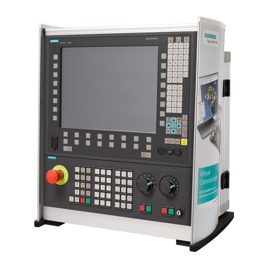
Introduction 1.2 Operator panel fronts Operator panel fronts 1.2.1 Overview Introduction The display (screen) and operation (e.g. hardkeys and softkeys) of the SINUMERIK Operate user interface use the operator panel front. In this example, the OP 010 operator panel front is used to illustrate the components that are available for operating the controller and machine tool. - Page 26 Introduction 1.2 Operator panel fronts Operator controls and indicators Status LED: POWER Status LED: TEMP (illuminated LEDs indicate increased wear) Alphabetic key group Numerical key group Softkeys Control key group Hotkey group Cursor key group USB interface Menu select key Menu forward button Machine area button Menu back key...
- Page 27 A more precise description as well as a view of the other operator panel fronts that can be used may be found in the following reference: Operator Components and Networking Manual; SINUMERIK 840D sl/840Di sl Turning Operating Manual, 02/2012, 6FC5398-8CP40-3BA0...
-
Page 28: Keys Of The Operator Panel
Introduction 1.2 Operator panel fronts 1.2.2 Keys of the operator panel The following keys and key combinations are available for operation of the controller and the machine tool. Keys and key combinations Function <ALARM CANCEL> Cancels alarms and messages that are marked with this symbol. - Page 29 Introduction 1.2 Operator panel fronts Function <NEXT WINDOW> + <CTRL> Moves the cursor to the beginning of a program. Moves the cursor in the first row of the current column. <NEXT WINDOW> + <CTRL> + <SHIFT> Moves the cursor to the beginning of a program. ...
- Page 30 Introduction 1.2 Operator panel fronts Function <Cursor right> + <CTRL> Editing box Moves the cursor further to the right by one word. Navigation Moves the cursor in a table to the next cell to the right. <Cursor left> ...
- Page 31 Introduction 1.2 Operator panel fronts Function <Cursor down> Editing box Moves the cursor downwards. Navigation – Moves the cursor in a table to the next cell downwards. – Moves the cursor in a window downwards. <Cursor down> + <CTRL> ...
- Page 32 Introduction 1.2 Operator panel fronts Function <END> + <CTRL> Moves the cursor to the last entry in the last line of the actual column or to the end of a program. <END> + <CTRL> + <SHIFT> Moves the cursor to the last entry in the last line of the actual column or to the end of a program.
- Page 33 Introduction 1.2 Operator panel fronts Function <CTRL> + <A> In the actual window, selects all entries (only in the program editor and program manager). <CTRL> + <C> Copies the selected content. <CTRL> + <E> Calls the "Ctrl Energy" function. <CTRL> + <F> Opens the search dialog in the machine data and setting data lists, when loading and saving in the MDA editor as well as in the program manager and in the system data.
- Page 34 Introduction 1.2 Operator panel fronts Function <CTRL> + <ALT> + <C> Creates a complete standard archive (.ARC) on an external data carrier (USB-FlashDrive) (for 840D sl / 828D). Note: Please refer to the machine manufacturer's specifications. <CTRL> + <ALT> + <S> Creates a complete standard archive (.ARC) on an external data carrier (USB-FlashDrive) (for 840D sl).
- Page 35 Introduction 1.2 Operator panel fronts Function <Spacebar> Editing window Inserts a space Switches between several specified options in selection drop-down list boxes and in selection boxes. <Plus> Opens a directory which contains the element. Increases the size of the graphic view for simulation and traces.
- Page 36 Introduction 1.2 Operator panel fronts Function <INPUT> Completes input of a value in the entry field. Opens a directory or a program. Inserts an empty program block if the cursor is positioned at the end of a program block. ...
-
Page 37: Machine Control Panels
1.3.1 Overview The machine tool can be equipped with a machine control panel by Siemens or with a specific machine control panel from the machine manufacturer. You use the machine control panel to initiate actions on the machine tool such as traversing an axis or starting the machining of a workpiece. - Page 38 Introduction 1.3 Machine control panels Machine manufacturer For additional responses to pressing the Emergency Stop button, please refer to the machine manufacturer's instructions. Installation locations for control devices (d = 16 mm) RESET Stop processing the current programs. The NCK control remains synchronized with the machine. It is in its initial state and ready for a new program run.
- Page 39 Introduction 1.3 Machine control panels Machine manufacturer A machine data code defines how the increment value is interpreted. Customer keys T1 to T15 Traversal axes with rapid traverse superposition and coordinate exchange Axis keys Selects an axis. Direction keys Select the traversing direction. <RAPID>...
-
Page 40: User Interface
Introduction 1.4 User interface User interface 1.4.1 Screen layout Overview Active operating area and mode Alarm/message line Program name Channel state and program control Channel operational messages Axis position display in actual value window Turning Operating Manual, 02/2012, 6FC5398-8CP40-3BA0... -
Page 41: Status Display
Introduction 1.4 User interface Display for active tool T current feedrate F active spindle with current status (S) Spindle utilization rate in percent Operating window with program block display Display of active G functions, all G functions, H functions and input window for different functions (for example, skip blocks, program control) Dialog line to provide additional user notes Horizontal softkey bar... - Page 42 Introduction 1.4 User interface Display Description "Program manager" operating area "Diagnosis" operating area "Start-up" operating area Active mode or submode "Jog" mode "MDA" mode "Auto" mode "Teach In" submode "Repos" submode "Ref Point" submode Alarms and messages Alarm display The alarm numbers are displayed in white lettering on a red background.
- Page 43 Introduction 1.4 User interface Second line Display Description Program path and program name The displays in the second line can be configured. Machine manufacturer Please also refer to the machine manufacturer's instructions. Third line Display Description Display of channel status. If several channels are present on the machine, the channel name is also displayed.
-
Page 44: Actual Value Window
Introduction 1.4 User interface Machine manufacturer Please also refer to the machine manufacturer's instructions. 1.4.3 Actual value window The actual values of the axes and their positions are displayed. Work/Machine The displayed coordinates are based on either the machine coordinate system or the workpiece coordinate system. -
Page 45: T,F,S Window
Introduction 1.4 User interface Overview of display Display Meaning Header columns Work/Machine Display of axes in selected coordinate system. Item Position of displayed axes. Display of distance-to-go The distance-to-go for the current NC block is displayed while the program is running. Feed/override The feed acting on the axes, as well as the override, are displayed in the full-screen version. - Page 46 Introduction 1.4 User interface Display Meaning Z value of the actual tool X value of the actual tool Feed data Display Meaning Feed disable Actual feed value If several axes traverse, is displayed for: "JOG" mode: Axis feed for the traversing axis ...
-
Page 47: Current Block Display
Introduction 1.4 User interface 1.4.5 Current block display The window of the current block display shows you the program blocks currently being executed. Display of current program The following information is displayed in the running program: ● The workpiece name or program name is entered in the title row. ●... - Page 48 Introduction 1.4 User interface Changing the operating area Press the <MENU SELECT> key and select the desired operating area using the horizontal softkey bar. You can call the "Machine" operating area directly using the key on the operator panel. Press the <MACHINE> key to select the "machine" operating area. Changing the operating mode You can select a mode or submode directly using the keys on the machine control panel or using the vertical softkeys in the main menu.
-
Page 49: Entering Or Selecting Parameters
Introduction 1.4 User interface 1.4.7 Entering or selecting parameters When setting up the machine and during programming, you must enter various parameter values in the entry fields. The background color of the fields provides information on the status of the entry field. Orange background The input field is selected Light orange background... - Page 50 Introduction 1.4 User interface Changing or calculating parameters If you only want to change individual characters in an input field rather than overwriting the entire entry, switch to insertion mode. In this mode, you can also enter simple calculation expressions, without having to explicitly call the calculator.
-
Page 51: Pocket Calculator
Introduction 1.4 User interface + <number> Enter "s" or "S" as well as the number x for which you would like to generate the square. Close the value entry using the <INPUT> key and the result is transferred into the field. Accepting parameters When you have correctly entered all necessary parameters, you can close the window and save your settings. - Page 52 Introduction 1.4 User interface Procedure Position the cursor on the desired entry field. Press the <=> key. The calculator is displayed. Input the arithmetic statement. You can use arithmetic symbols, numbers, and commas. Press the equals symbol on the calculator. - OR - Press the "Calculate"...
-
Page 53: Context Menu
Introduction 1.4 User interface 1.4.9 Context menu When you right-click, the context menu opens and provides the following functions: ● Cut Cut Ctrl+X ● Copy Copy Ctrl+C ● Paste Paste Ctrl+V Program editor Additional functions are available in the editor ●... -
Page 54: Changing The User Interface Language
Introduction 1.4 User interface 1.4.11 Changing the user interface language Procedure Select the "Start-up" operating area. Press the "Change language" softkey. The "Language selection" window opens. The language set last is selected. Position the cursor on the desired language. Press the "OK" softkey. - OR - Press the <INPUT>... - Page 55 Introduction 1.4 User interface The editor is available for the following Asian languages: ● Simplified Chinese ● Traditional Chinese ● Korean Note You require a special keyboard to enter Korean characters. Structure of editor Functions Pinyin input Editing of the dictionary Input of Latin letters Turning Operating Manual, 02/2012, 6FC5398-8CP40-3BA0...
- Page 56 Introduction 1.4 User interface Precondition The control has been set to Chinese or Korean. Procedure Editing characters Open the screen form and position the cursor on the entry field and press the <Alt +S> keys. The editor is displayed. Enter the desired phonetic notation. Click the <Cursor down>...
-
Page 57: Protection Levels
You have the option of providing softkeys with protection levels or completely hiding them. References For additional information, please refer to the following documentation: Commissioning Manual SINUMERIK Operate (IM9) / SINUMERIK 840D sl Softkeys Machine operating area Protection level End user... - Page 58 Introduction 1.4 User interface Diagnostics operating area Protection level Keyswitch 3 (protection level 4) User (protection level 3) User (protection level 3) Manufacturer (protection level 1) User (protection level 3) Service (protection level 2) Start-up operating area Protection levels End user (protection level 3) Keyswitch 3 (protection level 4)
-
Page 59: Online Help In Sinumerik Operate
Introduction 1.4 User interface 1.4.14 Online help in SINUMERIK Operate A comprehensive context-sensitive online help is stored in the control system. ● A brief description is provided for each window and, if required, step-by-step instructions for the operating sequences. ● A detailed help is provided in the editor for every entered G code. You can also display all G functions and take over a selected command directly from the help into the editor. - Page 60 Introduction 1.4 User interface Calling a topic in the table of contents Press the "Table of contents" softkey. Depending on which technology you are using, the Operating Manuals "Operator control Milling", "Operator control Turning" or "Operator control Universal" as well as the "Programming" Programming Manual are displayed.
- Page 61 Introduction 1.4 User interface Displaying alarm descriptions and machine data If messages or alarms are pending in the "Alarms", "Messages" or "Alarm Log" window, position the cursor at the appropriate display and press the <HELP> or the <F12> key. The associated alarm description is displayed. If you are in the "Start-up"...
- Page 62 Introduction 1.4 User interface Turning Operating Manual, 02/2012, 6FC5398-8CP40-3BA0...
-
Page 63: Setting Up The Machine
Setting up the machine Switching on and switching off Start-up When the control starts up, the main screen opens according to the operating mode specified by the machine manufacturer. In general, this is the main screen for the "REF POINT" submode. Machine manufacturer Please also refer to the machine manufacturer's instructions. -
Page 64: Approaching A Reference Point
Setting up the machine 2.2 Approaching a reference point Approaching a reference point 2.2.1 Referencing axes Your machine tool can be equipped with an absolute or incremental path measuring system. An axis with incremental path measuring system must be referenced after the controller has been switched on –... -
Page 65: User Agreement
Setting up the machine 2.2 Approaching a reference point Procedure Press the <JOG> key. Press the <REF. POINT> key. Select the axis to be traversed. Press the <-> or <+> key. The selected axis moves to the reference point. If you have pressed the wrong direction key, the action is not accepted and the axes do not move. - Page 66 Setting up the machine 2.2 Approaching a reference point Procedure Select the "Machine" operating area. Press the <REF POINT> key. Select the axis to be traversed. Press the <-> or <+> key. The selected axis moves to the reference point and stops. The coordinate of the reference point is displayed.
-
Page 67: Modes And Mode Groups
Setting up the machine 2.3 Modes and mode groups Modes and mode groups 2.3.1 General You can work in three different operating modes. "JOG" mode "JOG" mode is used for the following preparatory actions: ● Approach reference point, i.e. the machine axis is referenced ●... - Page 68 Setting up the machine 2.3 Modes and mode groups Selecting "Repos" Press the <REPOS> key. "MDA" mode (Manual Data Automatic) In "MDA" mode, you can enter and execute G code commands non-modally to set up the machine or to perform a single action. Selecting "MDA"...
-
Page 69: Modes Groups And Channels
Setting up the machine 2.3 Modes and mode groups 2.3.2 Modes groups and channels Every channel behaves like an independent NC. A maximum of one part program can be processed per channel. ● Control with 1channel One mode group exists. ●... - Page 70 Another channel can be selected by pressing one of the other softkeys. References Commissioning Manual SINUMERIK Operate (IM9) / SINUMERIK 840D sl Channel switchover via touch operation On the HT 8 and when using a touch screen operator panel, you can switch to the next channel or display the channel menu via touch operation in the status display.
-
Page 71: Settings For The Machine
Setting up the machine 2.4 Settings for the machine Settings for the machine 2.4.1 Switching over the coordinate system (MCS/WCS) The coordinates in the actual value display are relative to either the machine coordinate system or the workpiece coordinate system. By default, the workpiece coordinate system is set as a reference for the actual value display. -
Page 72: Switching The Unit Of Measurement
Setting up the machine 2.4 Settings for the machine 2.4.2 Switching the unit of measurement You can set millimeters or inches as the unit of measurement. Switching the unit of measurement always applies to the entire machine. All required information is automatically converted to the new unit of measurement, for example: ●... -
Page 73: Setting The Zero Offset
Setting up the machine 2.4 Settings for the machine 2.4.3 Setting the zero offset You can enter a new position value in the actual value display for individual axes when a settable zero offset is active. The difference between the position value in the machine coordinate system MCS and the new position value in the workpiece coordinate system WCS is saved permanently in the currently active zero offset (e.g. - Page 74 Setting up the machine 2.4 Settings for the machine Procedure Select the "JOG" mode in the "Machine" operating area. Press the "Set ZO" softkey. - OR - Press the ">>", "REL act. vals" and "Set REL" softkeys to set position values in the relative coordinate system.
-
Page 75: Measuring The Tool
Setting up the machine 2.5 Measuring the tool Measuring the tool The geometries of the machining tool must be taken into consideration when executing a part program. These are stored as tool offset data in the tool list. Each time the tool is called, the control considers the tool offset data. - Page 76 Setting up the machine 2.5 Measuring the tool Procedure Select "JOG" mode in the "Machine" operating area. Press the "Meas. tool" softkey. Press the "Manual" softkey. Press the "Select tool” softkey. The "Tool selection" window is opened. Select the tool that you wish to measure. The cutting edge position and the radius or diameter of the tool must already be entered in the tool list.
-
Page 77: Measuring A Tool With A Tool Probe
References For further information about lathes with B axis, please refer to the following reference: Commissioning Manual SINUMERIK Operate / SINUMERIK 840D sl The tool offset data is then calculated from the known position of the tool carrier reference point and the probe. - Page 78 Setting up the machine 2.5 Measuring the tool Adapting the user interface to calibrating and measuring functions The following selection options can be switched-in or switched-out: ● Calibration plane, measurement plane ● Probe ● Calibration feedrate (measuring feedrate) Preconditions ● If you wish to measure your tools with a tool probe, the machine manufacturer must parameterize special measuring functions for that purpose.
-
Page 79: Calibrating The Tool Probe
Setting up the machine 2.5 Measuring the tool Manually position the tool in the vicinity of the tool probe in such a way that any collisions can be avoided when the tool probe is being traversed in the corresponding direction. Press the <CYCLE START>... - Page 80 Setting up the machine 2.5 Measuring the tool Procedure Change the calibrating tool. Select the "JOG" mode in the "Machine" operating area. Press the "Meas. tool" and "Calibrate probe" softkeys. Press the "X" or "Z" softkey, depending on which point of the tool probe you wish to determine first.
-
Page 81: Measuring A Tool With A Magnifying Glass
Setting up the machine 2.5 Measuring the tool 2.5.4 Measuring a tool with a magnifying glass You can also use a magnifying glass to determine the tool dimensions, if this is available on the machine. In this case, SINUMERIK Operate calculates the tool offset data from the known positions of the tool carrier reference point and the cross-hairs of the magnifying glass. -
Page 82: Measuring The Workpiece Zero
Setting up the machine 2.6 Measuring the workpiece zero Measuring the workpiece zero The reference point for programming a workpiece is always the workpiece zero. To determine this zero point, measure the length of the workpiece and save the position of the cylinder's face surface in the direction Z in a zero offset. - Page 83 Setting up the machine 2.6 Measuring the workpiece zero Procedure Select "JOG" mode in the "Machine" operating area. Press the "Workpiece zero" softkey. The "Set Edge" window opens. Select "Measuring only" if you only want to display the measured values. - OR - Select the desired zero offset in which you want to store the zero point (e.g.
-
Page 84: Zero Offsets
Setting up the machine 2.7 Zero offsets Zero offsets Following reference point approach, the actual value display for the axis coordinates is based on the machine zero (M) of the machine coordinate system (Machine). The program for machining the workpiece, however, is based on the workpiece zero (W) of the workpiece coordinate system (Work). - Page 85 Setting up the machine 2.7 Zero offsets Coarse and fine offsets Every zero offset (G54 to G57, G505 to G599) consists of a coarse offset and a fine offset. You can call the zero offsets from any program (coarse and fine offsets are added together). You can save the workpiece zero, for example, in the coarse offset, and then store the offset that occurs when a new workpiece is clamped between the old and the new workpiece zero in the fine offset.
-
Page 86: Display Active Zero Offset
Setting up the machine 2.7 Zero offsets 2.7.1 Display active zero offset The following zero offsets are displayed in the "Zero Offset - Active" window: ● Zero offsets, for which active offsets are included, or for which values are entered. ●... -
Page 87: Displaying The Zero Offset "Overview
Setting up the machine 2.7 Zero offsets 2.7.2 Displaying the zero offset "overview" The active offsets or system offsets are displayed for all set-up axes in the "Zero Offset - Overview" window. In addition to the offset (course and fine), the rotation, scaling and mirroring defined using this are also displayed. -
Page 88: Displaying And Editing Base Zero Offset
Setting up the machine 2.7 Zero offsets 2.7.3 Displaying and editing base zero offset The defined channel-specific and global base offsets, divided into coarse and fine offsets, are displayed for all set-up axes in the "Zero offset - Base" window. Machine manufacturer Please refer to the machine manufacturer's specifications. -
Page 89: Displaying And Editing Settable Zero Offset
Setting up the machine 2.7 Zero offsets 2.7.4 Displaying and editing settable zero offset All settable offsets, divided into coarse and fine offsets, are displayed in the "Zero Offset - G54..G599" window. Rotation, scaling and mirroring are displayed. Procedure Select the "Parameter" operating area. Press the "Zero offset"... -
Page 90: Displaying And Editing Details Of The Zero Offsets
Setting up the machine 2.7 Zero offsets 2.7.5 Displaying and editing details of the zero offsets For each zero offset, you can display and edit all data for all axes. You can also delete zero offsets. For every axis, values for the following data will be displayed: ●... - Page 91 Setting up the machine 2.7 Zero offsets Press the "ZO +" or "ZO -" softkey to select the next or previous offset, respectively, within the selected area ("Active", "Base", "G54 to G599") without first having to switch to the overview window. If you have reached the end of the range (e.g.
-
Page 92: Deleting A Zero Offset
Setting up the machine 2.7 Zero offsets 2.7.6 Deleting a zero offset You have the option of deleting zero offsets. This resets the entered values. Procedure Select the "Parameter" operating area. Press the "Zero offset" softkey. Press the "Active", "Base" or "G54…G599" softkey. Press the "Details"... -
Page 93: Measuring The Workpiece Zero
Setting up the machine 2.7 Zero offsets 2.7.7 Measuring the workpiece zero Procedure Select the "Parameters" operating area and press the "Zero offset" softkey. Press the "G54...G599" softkey and select the zero offset in which the zero point is to be saved. Press the "Workpiece zero"... -
Page 94: Monitoring Axis And Spindle Data
Setting up the machine 2.8 Monitoring axis and spindle data Monitoring axis and spindle data 2.8.1 Specify working area limitations The "Working area limitation" function can be used to limit the range within which a tool can traverse in all channel axes. These commands allow you to set up protection zones in the working area which are out of bounds for tool movements. -
Page 95: Editing Spindle Data
Setting up the machine 2.8 Monitoring axis and spindle data 2.8.2 Editing spindle data The speed limits set for the spindles that must not be under- or overshot are displayed in the "Spindles" window. You can limit the spindle speeds in fields "Minimum" and "Maximum" within the limit values defined in the relevant machine data. -
Page 96: Spindle Chuck Data
Setting up the machine 2.8 Monitoring axis and spindle data 2.8.3 Spindle chuck data You store the chuck dimensions of the spindles at your machine in the "Spindle chuck data" window. Manually measuring a tool If you want to use the chuck of the main or counter spindle as a reference point during manual measuring, specify the chuck dimension ZC. - Page 97 Setting up the machine 2.8 Monitoring axis and spindle data Tailstock Dimensioning the tailstock The length of the tailstock (ZR) and the diameter of the tailstock (XR) of the spindle screen are needed for the display of the tailstock in the simulation. Procedure Select the "Parameter"...
- Page 98 Setting up the machine 2.8 Monitoring axis and spindle data Parameter Description Unit Main spindle chuck dimensions (inc) Jaw type Dimensions of the forward edge or stop edge Jaw type 1 Jaw type 2 Chuck dimension, counter-spindle (inc) - only for a counter-spindle that has been set-up Stop dimension, counter-spindle (inc) - only for a counter-spindle that has been set-up...
-
Page 99: Displaying Setting Data Lists
Setting up the machine 2.9 Displaying setting data lists Displaying setting data lists You can display lists with configured setting data. Machine manufacturer Please refer to the machine manufacturer's specifications. Procedure Select the "Parameter" operating area. Press the "Setting data" and "Data lists" softkeys. The "Setting Data Lists"... -
Page 100: Handwheel Assignment
Setting up the machine 2.10 Handwheel assignment 2.10 Handwheel assignment You can traverse the axes in the machine coordinate system (Machine) or in the workpiece coordinate system (Work) via the handwheel. Software option You require the "Extended operator functions" option for the handwheel offset (only for 828D). - Page 101 Setting up the machine 2.10 Handwheel assignment Press the corresponding softkey to select the desired axis (e.g. "X"). - OR Open the "Axis" selection box using the <INSERT> key, navigate to the desired axis, and press the <INPUT> key. Selecting an axis also activates the handwheel (e.g., "X" is assigned to handwheel no.
-
Page 102: Mda
Setting up the machine 2.11 MDA 2.11 In "MDA" mode (Manual Data Automatic mode), you can enter G-code commands block-by- block and immediately execute them for setting up the machine. You can load an MDA program straight from the Program Manager into the MDA buffer. You may also store programs which were rendered or changed in the MDA operating window into any directory of the Program Manager. -
Page 103: Saving An Mda Program
Setting up the machine 2.11 MDA 2.11.2 Saving an MDA program Procedure Select the "Machine" operating area. Press the <MDI> key. The MDI editor opens. Create the MDI program by entering the G-code commands using the operator's keyboard. Press the "Store MDI" softkey. The "Save from MDI: Select storage location"... -
Page 104: Executing An Mda Program
Setting up the machine 2.11 MDA 2.11.3 Executing an MDA program Proceed as follows Select the "Machine" operating area. Press the <MDA> key. The MDA editor opens. Input the desired G-code commands using the operator’s keyboard. Press the <CYCLE START> key. The control executes the input blocks. -
Page 105: Working In Manual Mode
Working in manual mode General Always use "JOG" mode when you want to set up the machine for the execution of a program or to carry out simple traversing movements on the machine: ● Synchronize the measuring system of the controller with the machine (reference point approach) ●... - Page 106 Working in manual mode 3.2 Selecting a tool and spindle Display Meaning Input of the tool (name or location number) You can select a tool from the tool list using the "Select tool" softkey. Cutting edge number of the tool (1 - 9) Spindle Spindle selection, identification with spindle number Spindle M function...
-
Page 107: Selecting A Tool
Working in manual mode 3.2 Selecting a tool and spindle 3.2.2 Selecting a tool Procedure Select the "JOG" operating mode. Press the "T, S, M" softkey. Enter the name or the number of the tool T in the entry field. - OR - Press the "Tool"... -
Page 108: Starting And Stopping The Spindle Manually
Working in manual mode 3.2 Selecting a tool and spindle 3.2.3 Starting and stopping the spindle manually Procedure Select the "T,S,M" softkey in the "JOG" mode. Select the desired spindle (e.g. S1) and enter the desired spindle speed or cutting speed in the right-hand entry field. If the machine has a gearbox for the spindle, set the gearing step. -
Page 109: Positioning The Spindle
Working in manual mode 3.2 Selecting a tool and spindle 3.2.4 Positioning the spindle Procedure Select the "T,S,M" softkey in the "JOG" mode. Select the "Stop Pos." setting in the "Spindle M function" field. The "Stop Pos." entry field appears. Enter the desired spindle stop position. -
Page 110: Traversing Axes
Working in manual mode 3.3 Traversing axes Traversing axes You can traverse the axes in manual mode via the Increment or Axis keys or handwheels. During a traverse initiated from the keyboard, the selected axis moves at the programmed setup feedrate. During an incremental traverse, the selected axis traverses a specified increment. -
Page 111: Traverse Axes By A Defined Increment
Working in manual mode 3.3 Traversing axes 3.3.1 Traverse axes by a defined increment You can traverse the axes in manual mode via the Increment and Axis keys or handwheels. Procedure Select the "Machine" operating area. Press the <JOG> key. Press keys 1, 10, etc. -
Page 112: Traversing Axes By A Variable Increment
Working in manual mode 3.3 Traversing axes 3.3.2 Traversing axes by a variable increment Procedure Select the "Machine" operating area. Press the <JOG> key. Press the "Settings" softkey. The "Settings for Manual Operation" window is opened. Enter the desired value for the "Variable increment" parameter. Example: Enter 500 for a desired increment of 500 μm (0.5 mm). -
Page 113: Positioning Axes
Working in manual mode 3.4 Positioning axes Positioning axes In order to implement simple machining sequences, you can traverse the axes to certain positions in manual mode. The feedrate / rapid traverse override is active during traversing. Procedure If required, select a tool. Select the "JOG"... -
Page 114: Manual Retraction
Working in manual mode 3.5 Manual retraction Manual retraction After the interruption in machining due to power loss or a RESET at the machine control panel, you have the possibility to retract the tool in the JOG mode in the tool direction without damaging the tool or the workpiece. - Page 115 Working in manual mode 3.5 Manual retraction Select the required axis in the "Retraction axis" selection box. Use the traversing keys (e.g. Z +) to traverse the tool from the workpiece according to the retraction axis selected in the "Retract Tool" window.
-
Page 116: Simple Stock Removal Of Workpiece
Working in manual mode 3.6 Simple stock removal of workpiece Simple stock removal of workpiece Some blanks have a smooth or even surface. For example, you can use the stock removal cycle to turn the face surface of the workpiece before machining actually takes place. If you want to bore out a collet using the stock removal cycle, you can program an undercut (XF2) in the corner. - Page 117 Working in manual mode 3.6 Simple stock removal of workpiece Procedure Press the "Machine" operating area key Press the <JOG> key. Press the "Stock removal" softkey. Enter desired values for the parameters. Press the "OK" softkey. The parameter screen is closed. Press the <CYCLE START>...
- Page 118 Working in manual mode 3.6 Simple stock removal of workpiece Parameter Description Unit Position Machining position Machining Face direction Longitudinal Reference point ∅ (abs) Reference point (abs) End point X ∅ (abs) or end point X in relation to X0 (inc) End point Z (abs) or end point Z in relation to X0 (inc) FS1...FS3 or R1...R3 Chamfer width (FS1...FS3) or rounding radius (R1...R3)
-
Page 119: Thread Synchronizing
Working in manual mode 3.7 Thread synchronizing Thread synchronizing If you wish to re-machine a thread, it may be necessary to synchronize the spindle to the existing thread turn. This is necessary as by reclamping the blank, an angular offset can occur in the thread. - Page 120 Working in manual mode 3.7 Thread synchronizing Press the "Teach-in counterspindle" softkey if you are working at the counterspindle. Note: The thread synchronization is activated by teaching in a spindle. In this case, the synchronizing positions of axes X and Z and the synchronizing angle of spindle (Sn) are saved in the Machine and displayed in the screen form.
-
Page 121: Default Settings For Manual Mode
Working in manual mode 3.8 Default settings for manual mode Default settings for manual mode Specify the configurations for manual mode in the "Settings for manual operation" window. Presettings Settings Description Type of feedrate Here, you select the type of feedrate. G94: Axis feedrate/linear feedrate ... - Page 122 Working in manual mode 3.8 Default settings for manual mode Turning Operating Manual, 02/2012, 6FC5398-8CP40-3BA0...
-
Page 123: Machining The Workpiece
Machining the workpiece Starting and stopping machining During execution of a program, the workpiece is machined in accordance with the programming on the machine. After the program is started in automatic mode, workpiece machining is performed automatically. Requirements The following requirements must be met before executing a program: ●... - Page 124 Machining the workpiece 4.1 Starting and stopping machining Stopping machining Press the <CYCLE STOP> key. Machining stops immediately. Individual program blocks are not executed to the end. On the next start, machining is resumed from the point where it left off. Canceling machining Press the <RESET>...
-
Page 125: Selecting A Program
Machining the workpiece 4.2 Selecting a program Selecting a program Procedure Select the "Program manager" operating area. The directory overview is opened. Place the cursor on the directory containing the program that you want to select. Press the <INPUT> key - OR - Press the <Cursor right>... -
Page 126: Executing A Trail Program Run
Machining the workpiece 4.3 Executing a trail program run Executing a trail program run When testing a program, the system can interrupt the machining of the workpiece after each program block, which triggers a movement or auxiliary function on the machine. In this way, you can control the machining result block-by-block during the initial execution of a program on the machine. - Page 127 Machining the workpiece 4.3 Executing a trail program run Procedure Press the "Prog. ctrl." softkey and select the desired variant in the "SBL" field. Press the <SINGLE BLOCK> key. Press the <CYCLE START> key. Depending on the execution variant, the first block will be executed. Then the machining stops.
-
Page 128: Displaying The Current Program Block
Machining the workpiece 4.4 Displaying the current program block Displaying the current program block 4.4.1 Current block display The window of the current block display shows you the program blocks currently being executed. Display of current program The following information is displayed in the running program: ●... -
Page 129: Display Program Level
Machining the workpiece 4.4 Displaying the current program block ● Other programmed addresses ● M functions Machine manufacturer Please refer to the machine manufacturer's specifications. Procedure A program is selected for execution and has been opened in the "Machine" operating area. Press the "Basic blocks"... - Page 130 Machining the workpiece 4.4 Displaying the current program block Display of program level The following information will be displayed: ● Level number ● Program name ● Block number, or line number ● Remain program run throughs (only for several program run throughs) Precondition A program must be selected for execution in "AUTO"...
-
Page 131: Correcting A Program
Machining the workpiece 4.5 Correcting a program Correcting a program As soon as a syntax error in the part program is detected by the controller, program execution is interrupted and the syntax error is displayed in the alarm line. Correction possibilities Depending on the state of the control system, you can make the following corrections using the Program editing function. - Page 132 Machining the workpiece 4.5 Correcting a program Procedure The program to be corrected is in the Stop or Reset mode. Press the "Prog. corr.” softkey The program is opened in the editor. The program preprocessing and the current block are displayed. The current block is also updated in the running program, but not the displayed program section, i.e.
-
Page 133: Repositioning Axes
Machining the workpiece 4.6 Repositioning axes Repositioning axes After a program interruption in automatic mode (e.g. after a tool breaks) you can move the tool away from the contour in manual mode. The coordinates of the interrupt position will be saved. The distances traversed in manual mode are displayed in the actual value window. - Page 134 Machining the workpiece 4.6 Repositioning axes Proceed as follows Press the <REPOS> key. Select the axes to be traversed one after the other. Press the <+> or <-> key for the relevant direction. The axes are moved to the interrupt position. Turning Operating Manual, 02/2012, 6FC5398-8CP40-3BA0...
-
Page 135: Starting Machining At A Specific Point
Machining the workpiece 4.7 Starting machining at a specific point Starting machining at a specific point 4.7.1 Use block search If you would only like to perform a certain section of a program on the machine, then you need not start the program from the beginning. You can also start the program from a specified program block. - Page 136 Machining the workpiece 4.7 Starting machining at a specific point Cascaded search You can start another search from the "Search target found" state. The cascading can be continued any number of times after every search target found. Note Another cascaded block search can be started from the stopped program execution only if the search target has been found.
-
Page 137: Continuing Program From Search Target
Machining the workpiece 4.7 Starting machining at a specific point 4.7.2 Continuing program from search target To continue the program at the desired position, press the <CYCLE START> key twice. ● The first CYCLE START outputs the auxiliary functions collected during the search. The program is then in the Stop state. -
Page 138: Defining An Interruption Point As Search Target
Machining the workpiece 4.7 Starting machining at a specific point 4.7.4 Defining an interruption point as search target Precondition A program was selected in "AUTO" mode and interrupted during execution through CYCLE STOP or RESET. Software option You require the "Extended operator functions" option (only for 828D). Procedure Press the "Block search"... -
Page 139: Entering The Search Target Via Search Pointer
Machining the workpiece 4.7 Starting machining at a specific point 4.7.5 Entering the search target via search pointer Enter the program point which you would like to proceed to in the "Search Pointer" window. Software option You require the "Extended operator functions" option for the "Search pointer" function (only for 828D). -
Page 140: Parameters For Block Search In The Search Pointer
Machining the workpiece 4.7 Starting machining at a specific point The Search window closes. The current block will be displayed in the "Program" window as soon as the target is found. Press the <CYCLE START> key twice. Processing is continued from the defined location. Note Interruption point You can load the interruption point in search pointer mode. - Page 141 Machining the workpiece 4.7 Starting machining at a specific point Search variants Block search mode Meaning With calculation It is used in order to be able to approach a target position in any circumstance (e.g. tool change position). - without approach The end position of the target block or the next programmed position is approached using the type of interpolation valid in the target block.
- Page 142 Machine manufacturer Please refer to the machine manufacturer's specifications. References For additional information, please refer to the following documentation: Commissioning Manual SINUMERIK Operate (IM9) / SINUMERIK 840D sl Procedure Select the "Machine" operating area. Press the <AUTO> key. Press the "Block search" and "Block search mode" softkeys.
-
Page 143: Controlling The Program Run
Machining the workpiece 4.8 Controlling the program run Controlling the program run 4.8.1 Program control You can change the program sequence in the "AUTO" and "MDA" modes. Abbreviation/program Mode of operation control The program is started and executed with auxiliary function outputs and dwell times. In this mode, the axes are not traversed. - Page 144 Machining the workpiece 4.8 Controlling the program run Activating program control You can control the program sequence however you wish by selecting and clearing the relevant checkboxes. Display / response of active program controls: If a program control is activated, the abbreviation of the corresponding function appears in the status display as response.
-
Page 145: Skip Blocks
Machining the workpiece 4.8 Controlling the program run 4.8.2 Skip blocks It is possible to skip program blocks, which are not to be executed every time the program runs. The skip blocks are identified by placing a "/" (forward slash) or "/x (x = number of skip level) character in front of the block number. - Page 146 Machining the workpiece 4.8 Controlling the program run Procedure Select the "Machine" operating area. Press the <AUTO> or <MDA> key. Press the "Prog. ctrl." and "Skip blocks" softkeys. The "Program Control" window appears and shows a list of skip levels. Turning Operating Manual, 02/2012, 6FC5398-8CP40-3BA0...
-
Page 147: Overstore
Machining the workpiece 4.9 Overstore Overstore With overstore, you have the option of executing technological parameters (for example, auxiliary functions, axis feed, spindle speed, programmable instructions, etc.) before the program is actually started. The program instructions act as if they are located in a normal part program. - Page 148 Machining the workpiece 4.9 Overstore Press the "Back" softkey. The "Overstore" window closes. Press the <CYCLE START> key again. The program selected before overstoring continues to run. Note Block-by-block execution The <SINGLE BLOCK> key is also active in the overstore mode. If several blocks are entered in the overstore buffer, then these are executed block-by-block after each NC start Deleting blocks Press the "Delete blocks"...
-
Page 149: Editing A Program
Machining the workpiece 4.10 Editing a program 4.10 Editing a program With the editor, you are able to render, supplement, or change part programs. Note The maximum block length is 512 characters. Calling the editor ● The editor is started via the "Program correction" function in the "Machine" operating area. -
Page 150: Searching In Programs
Machining the workpiece 4.10 Editing a program 4.10.1 Searching in programs You can use the search function to quickly arrive at points where you would like to make changes, e.g. in very large programs. Various search options are available that enable selective searching. Search options ●... -
Page 151: Replacing Program Text
Machining the workpiece 4.10 Editing a program Press the "OK" softkey to start the search. If the text you are searching for is found, the corresponding line is highlighted. Press the "Continue search" softkey if the text located during the search does not correspond to the point you are looking for. - Page 152 Machining the workpiece 4.10 Editing a program Press the "OK" softkey to start the search. If the text you are searching for is found, the corresponding line is highlighted. Press the "Replace" softkey to replace the text. - OR - Press the "Replace all"...
-
Page 153: Copying/Pasting/Deleting A Program Block
Machining the workpiece 4.10 Editing a program 4.10.3 Copying/pasting/deleting a program block Precondition The program is opened in the editor. Procedure Press the "Mark" softkey. - OR - Press the <SELECT> key. Select the desired program blocks with the cursor or mouse. Press the "Copy"... -
Page 154: Renumbering A Program
Machining the workpiece 4.10 Editing a program 4.10.4 Renumbering a program You can modify the block numbering of programs opened in the editor at a later point in time. Requirement The program is opened in the editor. Procedure Press the ">>" softkey. A new vertical softkey bar appears. -
Page 155: Creating A Program Block
Machining the workpiece 4.10 Editing a program 4.10.5 Creating a program block In order to structure programs to achieve a higher degree of transparency, you have the option of combining several blocks (G-code and/or ShopTurn machining steps) to form program blocks. You then have the option of opening and closing these blocks depending on your requirement. -
Page 156: Opening Additional Programs
Machining the workpiece 4.10 Editing a program 4.10.6 Opening additional programs You have the option of viewing and editing two programs simultaneously in the editor. For instance, you can copy program blocks or machining steps of a program and paste them into another program. -
Page 157: Editor Settings
Machining the workpiece 4.10 Editing a program See also Copying/pasting/deleting a program block (Page 153) 4.10.7 Editor settings Enter the default settings in the "Settings" window that are to take effect automatically when the editor is opened. Defaults Setting Meaning Number Yes: A new block number will automatically be assigned after every line automatically... - Page 158 Machining the workpiece 4.10 Editing a program Setting Meaning Width of the program Here, you enter the width of the program that has the input focus, in the editor with focus as a percentage of the window width. Cut only after Yes: The cut of program sections is possible only when program lines have selecting been selected, i.e.
-
Page 159: Mold Making View
Machining the workpiece 4.11 Mold making view 4.11 Mold making view 4.11.1 Mold making view For large mold making programs, as provided by CAD systems, you have the option, using a fast view, to display the machining paths. This allows you to obtain a fast overview of the program and possibly correct it. - Page 160 Machining the workpiece 4.11 Mold making view NC blocks that can be interpreted Following NC blocks are supported for the mold building view. ● Types – Lines G0, G1 with X Y Z – Circles G2, G3 with center point I, J, K or radius CR, depending on the working plane G17, G18, G19, CIP with circular point I1, J1, K1 or radius CR –...
-
Page 161: Starting The Mold Making View
Machining the workpiece 4.11 Mold making view Changing and adapting the mold making view Just the same as for simulation and simultaneous recording, you have the option of changing and adapting the simulation graphical representation in order to achieve the optimum view. ●... -
Page 162: Specifically Jump To The Program Block
Machining the workpiece 4.11 Mold making view 4.11.3 Specifically jump to the program block If you notice anything peculiar in the graphic or identify an error, then from this location, you can directly jump to the program block involved to possibly edit the program. Preconditions ●... -
Page 163: Searching For Program Blocks
Machining the workpiece 4.11 Mold making view 4.11.4 Searching for program blocks Using the "Search" function, you can search for specific program blocks as well as edit programs; you can do this in one step by replacing the text that you are searching for by a new text. -
Page 164: Changing The View
Machining the workpiece 4.11 Mold making view 4.11.5 Changing the view 4.11.5.1 Enlarging or reducing the graphical representation Precondition ● The mold making view has been started. ● The "Graphic" softkey is active. Procedure Press the <+> and <-> keys if you wish to enlarge or reduce the graphic display. -
Page 165: Modifying The Viewport
Machining the workpiece 4.11 Mold making view 4.11.5.2 Modifying the viewport Use the magnifying glass if you would like to move, increase or reduce the size of the section of the mold making view, e.g. to view details or display the complete workpiece. Using the magnifying glass, you can define your own segment and then increase or decrease its size. -
Page 166: Displaying G Functions And Auxiliary Functions
Machining the workpiece 4.12 Displaying G functions and auxiliary functions 4.12 Displaying G functions and auxiliary functions 4.12.1 Selected G functions 16 selected G groups are displayed in the "G Function" window. Within a G group, the G function currently active in the controller is displayed. Some G codes (e.g. - Page 167 Machining the workpiece 4.12 Displaying G functions and auxiliary functions Group Meaning G group 3 Programmable offsets, working area limitations and pole programming (e.g. TRANS, ROT, G25, G110) G group 6 Plane selection (e.g. G17, G18) G group 7 Tool radius compensation (e.g. G40, G42) G group 8 Settable work offset (e.g.
-
Page 168: All G Functions
References For more information about configuring the displayed G groups, refer to the following document: Commissioning Manual SINUMERIK Operate (IM9) / SINUMERIK 840D sl 4.12.2 All G functions All G groups and their group numbers are listed in the "G Functions" window. -
Page 169: Auxiliary Functions
Machining the workpiece 4.12 Displaying G functions and auxiliary functions Procedure Select the "Machine" operating area. Press the <JOG>, <MDA> or <AUTO> key. Press the ">>" and "All G functions" softkeys. The "G Functions" window is opened. 4.12.3 Auxiliary functions Auxiliary functions include M and H functions preprogrammed by the machine manufacturer, which transfer parameters to the PLC to trigger reactions defined by the manufacturer. - Page 170 Machining the workpiece 4.12 Displaying G functions and auxiliary functions Press the "H functions" softkey. The "Auxiliary Functions" window opens. Press the "H functions" softkey again to hide the window again. You can display status information for diagnosing synchronized actions in the "Synchronized Actions"...
- Page 171 Machining the workpiece 4.12 Displaying G functions and auxiliary functions Procedure Select the "Machine" operating area. Press the <AUTO>, <MDA> or <JOG> key. Press the menu forward key and the "Synchron." softkey. The "Synchronized Actions" window appears. You obtain a display of all activated synchronized actions. Press the "ID"...
-
Page 172: Displaying The Program Runtime And Counting Workpieces
Machining the workpiece 4.13 Displaying the program runtime and counting workpieces 4.13 Displaying the program runtime and counting workpieces To gain an overview of the program runtime and the number of machined workpieces, open the "Times, Counter" window. Machine manufacturer Please refer to the machine manufacturer's specifications. - Page 173 Machining the workpiece 4.13 Displaying the program runtime and counting workpieces Procedure Select the "Machine" operating area. Press the <AUTO> key. Press the "Times, Counter" softkey. The "Times, Counter" window opens. Select "Yes" under "Count workpieces" if you want to count completed workpieces.
-
Page 174: Setting For Automatic Mode
Machining the workpiece 4.14 Setting for automatic mode 4.14 Setting for automatic mode Before machining a workpiece, you can test the program in order to identify programming errors early on. Use the dry run feedrate for this purpose. In addition, you have the option of additionally limiting the traversing speed for rapid traverse so that when running-in a new program with rapid traverse, no undesirable high traversing speeds occur. - Page 175 Machining the workpiece 4.14 Setting for automatic mode References Programming Manual Measuring Cycles / 840D sl/828D Note The feedrate can be changed while the operation is running. See also Program control (Page 143) Turning Operating Manual, 02/2012, 6FC5398-8CP40-3BA0...
- Page 176 Machining the workpiece 4.14 Setting for automatic mode Turning Operating Manual, 02/2012, 6FC5398-8CP40-3BA0...
-
Page 177: Simulating Machining
Simulating machining Overview During simulation, the current program is calculated in its entirety and the result displayed in graphic form. The result of programming is verified without traversing the machine axes. Incorrectly programmed machining steps are detected at an early stage and incorrect machining on the workpiece prevented. - Page 178 The traversing paths of the tool are shown in color. Rapid traverse is red and the feedrate is green. Note Displaying the tailstock The tailstock is only visible with the option "ShopMill/ShopTurn". Machine manufacturer Please also refer to the machine manufacturer's specifications. References Commissioning Manual SINUMERIK Operate (IM9) / SINUMERIK 840D sl Turning Operating Manual, 02/2012, 6FC5398-8CP40-3BA0...
- Page 179 Simulating machining 5.1 Overview Simulation display You can choose one of the following types of display: ● Material removal simulation During simulation or simultaneous recording you can follow stock removal from the defined blank. ● Path display You have the option of including the display of the path. The programmed tool path is displayed.
- Page 180 Simulating machining 5.1 Overview Status display The current axis coordinates, the override, the current tool with cutting edge, the current program block, the feedrate and the machining time are displayed. In all views, a clock is displayed during graphical processing. The machining time is displayed in hours, minutes and seconds.
- Page 181 Simulating machining 5.1 Overview Constraint ● Referencing: G74 from a program run does not function. ● Alarm 15110 "REORG block not possible" is not displayed. ● Compile cycles are only partly supported. ● No PLC support. ● Axis containers are not supported. ●...
- Page 182 Simulating machining 5.1 Overview Example An example for supported kinematics is a lathe with B axis: Lathe with B axis See also Spindle chuck data (Page 96) Turning Operating Manual, 02/2012, 6FC5398-8CP40-3BA0...
-
Page 183: Simulation Before Machining Of The Workpiece
Simulating machining 5.2 Simulation before machining of the workpiece Simulation before machining of the workpiece Before machining the workpiece on the machine, you have the option of performing a quick run-through in order to graphically display how the program will be executed. This provides a simple way of checking the result of the programming. - Page 184 Simulating machining 5.2 Simulation before machining of the workpiece - OR - Press the "Reset" softkey to cancel the simulation. Press the "Start" softkey to restart or continue the simulation. Note Operating area switchover The simulation is exited if you switch into another operating area. If you restart the simulation, then this starts again at the beginning of the program.
-
Page 185: Simultaneous Recording Before Machining Of The Workpiece
Simulating machining 5.3 Simultaneous recording before machining of the workpiece Simultaneous recording before machining of the workpiece Before machining the workpiece on the machine, you can graphically display the execution of the program on the screen to monitor the result of the programming. You can replace the programmed feedrate with a dry run feedrate to influence the speed of execution and select the program test to disable axis motion. -
Page 186: Simultaneous Recording During Machining Of The Workpiece
Simulating machining 5.4 Simultaneous recording during machining of the workpiece Simultaneous recording during machining of the workpiece If the view of the work space is blocked by coolant, for example, while the workpiece is being machined, you can also track the program execution on the screen. Software option You require the option "Simultaneous recording (real-time simulation)"... -
Page 187: Different Views Of The Workpiece
Simulating machining 5.5 Different views of the workpiece Different views of the workpiece In the graphical display, you can choose between different views so that you constantly have the best view of the current workpiece machining, or in order to display details or the overall view of the finished workpiece. -
Page 188: Face View
Simulating machining 5.5 Different views of the workpiece 5.5.3 Face view Start the simulation. Press the "Other views" and "Face view" softkeys. The side view shows the workpiece in the X-Y plane. Changing the display You can increase or decrease the size of the simulation graphic and move it, as well as change the segment. -
Page 189: 2-Window
Simulating machining 5.5 Different views of the workpiece 5.5.5 2-window Start the simulation. Press the "Additional views" and "2-window view" softkeys. The 2-window view contains a side view (left-hand window) and a front view (right-hand window) of the workpiece. The viewing direction is always from the front to the cutting surface even if machining is to be performed from behind or from the back side. -
Page 190: Graphical Display
Simulating machining 5.6 Graphical display Graphical display Figure 5-1 2-window view Active window The currently active window has a lighter background than the other view windows. Switch over the active window using the <Next Window> key. You can change the workpiece display here, e.g. increase or decrease the size, turn it and move it. -
Page 191: Editing The Simulation Display
Simulating machining 5.7 Editing the simulation display Editing the simulation display 5.7.1 Blank display You have the option of replacing the blank defined in the program or to define a blank for programs in which a blank definition cannot be inserted. Note The unmachined part can only be entered if simulation or simultaneous recording is in the reset state. -
Page 192: Program Control During The Simulation
Simulating machining 5.8 Program control during the simulation Program control during the simulation 5.8.1 Changing the feedrate You can change the feedrate at any time during the simulation. You can track the changes in the status line. Note If you are working with the "Simultaneous recording" function, the rotary switch (override) on the control panel is used. -
Page 193: Simulating The Program Block By Block
Simulating machining 5.8 Program control during the simulation 5.8.2 Simulating the program block by block You can control the program execution during simulation, i.e. execute a program block by block, as when executing a program. Procedure Simulation is started. Press the "Program control" and "Single block" softkeys. Press the "Back"... -
Page 194: Editing And Adapting A Simulation Graphic
Simulating machining 5.9 Editing and adapting a simulation graphic Editing and adapting a simulation graphic 5.9.1 Enlarging or reducing the graphical representation Precondition The simulation or the simultaneous recording is started. Procedure Press the <+> and <-> keys if you wish to enlarge or reduce the graphic display. -
Page 195: Panning A Graphical Representation
Simulating machining 5.9 Editing and adapting a simulation graphic 5.9.2 Panning a graphical representation Precondition The simulation or the simultaneous recording is started. Procedure Press a cursor key if you wish to move the graphic up, down, left, or right. 5.9.3 Rotating the graphical representation In the 3D view you can rotate the position of the workpiece to view it from all sides. -
Page 196: Modifying The Viewport
Simulating machining 5.9 Editing and adapting a simulation graphic Press the "Arrow right", "Arrow left", "Arrow up", "Arrow down", "Arrow clockwise" and "Arrow counterclockwise" softkeys to change the position of the workpiece. - OR - Keep the <Shift> key pressed and then turn the workpiece in the desired direction using the appropriate cursor keys. -
Page 197: Defining Cutting Planes
Simulating machining 5.9 Editing and adapting a simulation graphic Press the "Magnify -" or <-> softkey to reduce the frame. - OR - Press one of the cursor keys to move the frame up, down, left or right. Press the "Accept" softkey to accept the section. 5.9.5 Defining cutting planes In the 3D view, you have the option of "cutting"... -
Page 198: Displaying Simulation Alarms
Simulating machining 5.10 Displaying simulation alarms 5.10 Displaying simulation alarms Alarms might occur during simulation. If an alarm occurs during a simulation run, a window opens in the operating window to display it. The alarm overview contains the following information: ●... -
Page 199: Creating A G Code Program
Creating a G code program Graphical programming Functions The following functionality is available: ● Technology-oriented program step selection (cycles) using softkeys ● Input windows for parameter assignment with animated help screens ● Context-sensitive online help for every input window ● Support with contour input (geometry processor) Call and return conditions ●... -
Page 200: Program Views
Creating a G code program 6.2 Program views Program views You can display a G code program in various ways. ● Program view ● Parameter screen, either with help screen or graphic view Program view The program view in the editor provides an overview of the individual machining steps of a program. - Page 201 Creating a G code program 6.2 Program views Parameter screen with help display Press the <Cursor right> key to open a selected program block or cycle in the program view. The associated parameter screen with help screen is then displayed. Figure 6-2 Parameter screen with help display The animated help displays are always displayed with the correct orientation to the selected...
- Page 202 Creating a G code program 6.2 Program views Parameter screen with graphic view Using the "Graphic view" softkey, you can toggle between the help screen and the graphic view in the screen. Figure 6-3 Parameter screen with a graphical view of a G code program block Turning Operating Manual, 02/2012, 6FC5398-8CP40-3BA0...
-
Page 203: Program Structure
Creating a G code program 6.3 Program structure Program structure G_code programs can always be freely programmed. The most important commands that are included in the rule: ● Set a machining plane ● Call a tool (T and D) ● Call a work offset ●... -
Page 204: Fundamentals
Creating a G code program 6.4 Fundamentals Fundamentals 6.4.1 Machining planes A plane is defined by means of two coordinate axes. The third coordinate axis (tool axis) is perpendicular to this plane and determines the infeed direction of the tool (e.g. for 2½-D machining). -
Page 205: Programming A Tool (T)
Creating a G code program 6.4 Fundamentals For G17, reference points in the plane are called X0 Y0, for G18 they are called Z0 X0 - and for G19, they are called Y0 Z0. The depth specification in the tool axis for G17 is called Z1, for G18, Y1 and for G19, X1. -
Page 206: Generating A G Code Program
Creating a G code program 6.5 Generating a G code program Generating a G code program Create a separate program for each new workpiece that you would like to produce. The program contains the individual machining steps that must be performed to produce the workpiece. - Page 207 Creating a G code program 6.5 Generating a G code program See also Changing a cycle call (Page 218) Selection of the cycles via softkey (Page 211) Creating a new workpiece (Page 704) Turning Operating Manual, 02/2012, 6FC5398-8CP40-3BA0...
-
Page 208: Blank Input
Creating a G code program 6.6 Blank input Blank input 6.6.1 Function Function The blank is used for the simulation and the simultaneous recording. A useful simulation can only be achieved with a blank that is as close as possible to the real blank. Create a separate program for each new workpiece that you would like to produce. - Page 209 Creating a G code program 6.6 Blank input Procedure Select the "Program" operating area. Press the "Misc." and "Blank" softkeys. The "Blank Input" window opens. Parameter Description Unit Data for Selection of the spindle for the blank Main spindle Counterspindle ...
-
Page 210: Machining Plane, Milling Direction, Retraction Plane, Safe Clearance And Feedrate (Pl, Rp, Sc, F)
Creating a G code program 6.7 Machining plane, milling direction, retraction plane, safe clearance and feedrate (PL, RP, SC, F) Machining plane, milling direction, retraction plane, safe clearance and feedrate (PL, RP, SC, F) In the program header, cycle input screens have general parameters that always repeat. You will find the following parameters in every input screen for a cycle in a G code program. -
Page 211: Selection Of The Cycles Via Softkey
Creating a G code program 6.8 Selection of the cycles via softkey Selection of the cycles via softkey Overview of the machining steps The following machining steps are available. All of the cycles/functions available in the control are shown in this display. However, at a specific system, only the steps possible corresponding to the selected technology can be selected. - Page 212 Creating a G code program 6.8 Selection of the cycles via softkey ⇒ ⇒ ⇒ ⇒ ⇒ Turning Operating Manual, 02/2012, 6FC5398-8CP40-3BA0...
- Page 213 Creating a G code program 6.8 Selection of the cycles via softkey ⇒ ⇒ ⇒ ⇒ ⇒ Turning Operating Manual, 02/2012, 6FC5398-8CP40-3BA0...
- Page 214 Creating a G code program 6.8 Selection of the cycles via softkey ⇒ ⇒ ⇒ ⇒ ⇒ ⇒ ⇒ Turning Operating Manual, 02/2012, 6FC5398-8CP40-3BA0...
- Page 215 A menu tree with all of the available measuring versions of the measuring cycle function "Measure workpiece" can be found in the following reference: Programming Manual Measuring cycles / SINUMERIK 840D sl/828D ⇒ A menu tree with all of the available measuring versions of the measuring cycle function "Measure tool"...
-
Page 216: Calling Technology Cycles
These are then generated with the appropriate default values when the cycles are called. For additional information, please refer to the following references: Commissioning Manual SINUMERIK Operate (IM9) / SINUMERIK 840D sl Cycle support Example Use the softkeys to select whether you want support for programming contours, turning, drilling or milling cycles. -
Page 217: Checking Cycle Parameters
Creating a G code program 6.9 Calling technology cycles 6.9.3 Checking cycle parameters The entered parameters are already checked during the program creation in order to avoid faulty entries. If a parameter is assigned an illegal value, this is indicated in the input screen and is designated as follows: ●... -
Page 218: Changing A Cycle Call
Creating a G code program 6.9 Calling technology cycles 6.9.5 Changing a cycle call You have called the desired cycle via softkey in the program editor, entered the parameters and confirmed with "Accept". Procedure Select the desired cycle call and press the <Cursor right> key. The associated input screen of the selected cycle call is opened. -
Page 219: Additional Functions In The Input Screens
Creating a G code program 6.9 Calling technology cycles 6.9.7 Additional functions in the input screens Selection of units If, for example, the unit can be switched in a field, this is highlighted as soon as the cursor is positioned on the element. In this way, the operator recognizes the dependency. -
Page 220: Measuring Cycle Support
Software option You require the "Measuring cycles" option to use "Measuring cycles". References You will find a more detailed description on how to use measuring cycles in: Programming Manual Measuring cycles / SINUMERIK 840D sl/828D Turning Operating Manual, 02/2012, 6FC5398-8CP40-3BA0... -
Page 221: Creating A Shopturn Program
Creating a ShopTurn program Graphic program control, ShopTurn programs The program editor offers graphic programming to generate machining step programs that you can directly generate at the machine. Software option You require the "ShopMill/ShopTurn" option to generate ShopTurn machining step programs. Functions The following functionality is available: ●... -
Page 222: Program Views
Creating a ShopTurn program 7.2 Program views Program views You can display a ShopTurn program in various views: ● Machining schedule ● Programming graphics ● Parameter screen, either with help display or programming graphics Machining schedule The machining schedule in the editor provides an overview of the individual machining steps of a program. - Page 223 Creating a ShopTurn program 7.2 Program views Programming graphics The programming graphics show the contour of the workpiece as a dynamic graphic with dotted lines. The program block selected in the machining schedule is highlighted in color in the programming graphics. Figure 7-2 Programming graphics of a ShopTurn program Turning...
- Page 224 Creating a ShopTurn program 7.2 Program views Parameter screen with help display and programming graphics Press the <Cursor right> key to open a selected program block or cycle in the machining schedule. The associated parameter screen with help screen is then displayed.
- Page 225 Creating a ShopTurn program 7.2 Program views Figure 7-4 Parameter screen with programming graphics Turning Operating Manual, 02/2012, 6FC5398-8CP40-3BA0...
-
Page 226: Program Structure
Creating a ShopTurn program 7.3 Program structure Program structure A machining step program is divided into three sub-areas: ● Program header ● Program blocks ● End of program These sub-areas form a process plan. Program header The program header contains parameters that affect the entire program, such as blank dimensions or retraction planes. -
Page 227: Fundamentals
Creating a ShopTurn program 7.4 Fundamentals Fundamentals 7.4.1 Machining planes A workpiece can be machined on different planes. Two coordinate axes define a machining plane. On lathes with X, Z, and C axes, three planes are available: ● Turning ● Face ●... - Page 228 Creating a ShopTurn program 7.4 Fundamentals Turning The turning machining plane corresponds to the X/Z plane (G18). Face/Face C The Face/Face C machining plane corresponds to the X/Y plane (G17). For machines without a Y axis, however, the tools can only move in the X/Z plane. The X/Y coordinates that have been entered are automatically transformed into a movement in the X and C axis.
-
Page 229: Machining Cycle, Approach/Retraction
Creating a ShopTurn program 7.4 Fundamentals 7.4.2 Machining cycle, approach/retraction Approaching and retracting during the machining cycle always follows the same pattern if you have not defined a special approach/retraction cycle. If your machine has a tailstock, you can also take this into consideration when traversing. The retraction for a cycle ends at the safety clearance. - Page 230 Creating a ShopTurn program 7.4 Fundamentals Taking into account the tailstock Figure 7-6 Approach/retraction taking into account the tailstock ● The tool traverses in rapid traverse from the tool change point along the shortest path to the retraction plane XRR from the tailstock. ●...
-
Page 231: Absolute And Incremental Dimensions
Creating a ShopTurn program 7.4 Fundamentals 7.4.3 Absolute and incremental dimensions When generating a machining step program, you can input positions in absolute or incremental dimensions, depending on how the workpiece drawing is dimensioned. You can also use a combination of absolute and incremental dimensions, i.e. one coordinate as an absolute dimension and the other as an incremental dimension. - Page 232 Creating a ShopTurn program 7.4 Fundamentals Incremental dimensions (INC) With incremental dimensions (also referred to as sequential dimensions) a position specification refers to the previously programmed point, i.e. the input value corresponds to the path to be traversed. As a rule, the plus/minus sign does not matter when entering the incremental value, only the absolute value of the increment is evaluated.
-
Page 233: Polar Coordinates
Creating a ShopTurn program 7.4 Fundamentals 7.4.4 Polar coordinates You can specify positions using right-angled coordinates or polar coordinates. If a point in a workpiece drawing is defined by a value for each coordinate axis, you can easily input the position into the parameter screen form using right-angled coordinates. For workpieces that are dimensioned with arcs or angular data, it is often easier if you input the positions using polar coordinates. -
Page 234: Clamping The Spindle
Creating a ShopTurn program 7.4 Fundamentals 7.4.5 Clamping the spindle The "Clamp spindle" function must be set up by the machine manufacturer. Machine manufacturer Please refer to the machine manufacturer's specifications. Note for selecting the clamp spindle function under ShopTurn The machine manufacturer also specifies whether ShopTurn will clamp the spindle automatically if this would facilitate machining, or if you can decide the types of machining for which the spindle should be clamped. -
Page 235: Creating A Shopturn Program
Creating a ShopTurn program 7.5 Creating a ShopTurn program Creating a ShopTurn program Create a separate program for each new workpiece that you would like to produce. The program contains the individual machining steps that must be performed to produce the workpiece. - Page 236 Creating a ShopTurn program 7.5 Creating a ShopTurn program Filling out the program header Select a zero offset. Enter the dimensions of the blank and the parameter, which are effective over the complete program, e.g. dimension units in mm or inch, tool axis, retraction plane, safety clearance and machining direction.
-
Page 237: Program Header
Creating a ShopTurn program 7.6 Program header Program header In the program header, set the following parameters, which are effective for the complete program. Parameters Description Unit Measurement unit The setting of the measurement unit in the program header only refers to the position data in the actual program. - Page 238 Creating a ShopTurn program 7.6 Program header Parameters Description Unit Retraction plane Z front (abs) or retraction plane Z referred to ZA (inc) Retraction plane X external ∅ (abs) or retraction plane X referred to XA (inc) Retraction plane X internal ∅ (abs) or retraction plane X referred to XI (inc) Retraction plane Z front (abs) or retraction plane Z referred to ZA (inc)
-
Page 239: Generating Program Blocks
Creating a ShopTurn program 7.7 Generating program blocks Generating program blocks After a new program is created and the program header is filled out, define the individual machining steps in program blocks that are necessary to machine the workpiece. You can only create the program blocks between the program header and the program end. Procedure Selecting a technological function Position the cursor in the work plan on the line behind which a new... -
Page 240: Tool, Offset Value, Feedrate And Spindle Speed (T, D, F, S, V)
Creating a ShopTurn program 7.8 Tool, offset value, feedrate and spindle speed (T, D, F, S, V) Tool, offset value, feedrate and spindle speed (T, D, F, S, V) The following parameters should be entered for every program block. Tool (T) Each time a workpiece is machined, you must program a tool. - Page 241 Creating a ShopTurn program 7.8 Tool, offset value, feedrate and spindle speed (T, D, F, S, V) Feedrate (F) The feedrate F (also referred to as the machining feedrate) specifies the speed at which the axes move when machining the workpiece. The machining feedrate is entered in mm/min, mm/rev or in mm/tooth.
- Page 242 Creating a ShopTurn program 7.8 Tool, offset value, feedrate and spindle speed (T, D, F, S, V) Converting the spindle speed (S) / cutting rate (V) when milling As an alternative to the cutting rate, you can also program the spindle speed. For the milling cycles, the cutting rate (m/min) that is entered is automatically converted into the spindle speed (rpm) using the tool diameter - and vice versa.
-
Page 243: Call Work Offsets
Creating a ShopTurn program 7.9 Call work offsets Call work offsets You can call work offsets (G54, etc.) from any program. You define work offsets in work offset lists. You can also view the coordinates of the selected offset here. Procedure Press the "Various", "Transformations"... -
Page 244: Repeating Program Blocks
Creating a ShopTurn program 7.10 Repeating program blocks 7.10 Repeating program blocks If certain steps when machining a workpiece have to be executed more than once, it is only necessary to program these steps once. You have the option of repeating program blocks. NOTICE Machining several workpieces The program repeat function is not suitable to program repeat machining of parts. - Page 245 Creating a ShopTurn program 7.10 Repeating program blocks Press the "Set marker" and "Accept" softkeys again. An end marker is inserted after the actual block. Continue programming up to the point where you want to repeat the program blocks. Press the "Various" and "Repeat progr." softkeys. Enter the names of the start and end markers and the number of times the blocks are to be repeated.
-
Page 246: Entering The Number Of Workpieces
Creating a ShopTurn program 7.11 Entering the number of workpieces 7.11 Entering the number of workpieces If you wish to produce a certain quantity of the same workpiece, then at the end of the program, specify that you wish to repeat the program. If your machine has a bar loader for example, you can program the reloading of the workpiece and then the actual machining at the beginning of the program. -
Page 247: Changing Program Blocks
Creating a ShopTurn program 7.12 Changing program blocks 7.12 Changing program blocks You can subsequently optimize the parameters in the programmed blocks or adapt them to new situations, e.g. if you want to increase the feedrate or shift a position. In this case, you can directly change all the parameters in every program block in the associated parameter screen form. -
Page 248: Changing Program Settings
Creating a ShopTurn program 7.13 Changing program settings 7.13 Changing program settings Function All parameters specified in the program header with the exception of the blank shape and the unit of measurement can be changed at any point in the program. It is also possible to change the basic setting for the direction of rotation of machining in the case of milling. - Page 249 Creating a ShopTurn program 7.13 Changing program settings Parameters Parameter Description Unit Retraction Lift mode simple Extended Retraction plane X external ∅ (abs) or retraction plane X referred to XA (inc) Retraction plane X internal ∅ (abs) or retraction plane X referred to XI (inc) - (only for retraction "extended"...
-
Page 250: Selection Of The Cycles Via Softkey
Creating a ShopTurn program 7.14 Selection of the cycles via softkey 7.14 Selection of the cycles via softkey Overview of the machining steps The following machining steps are available. All of the cycles/functions available in the control are shown in this display. However, at a specific system, only the steps possible corresponding to the selected technology can be selected. - Page 251 Creating a ShopTurn program 7.14 Selection of the cycles via softkey ⇒ ⇒ ⇒ ⇒ Turning Operating Manual, 02/2012, 6FC5398-8CP40-3BA0...
- Page 252 Creating a ShopTurn program 7.14 Selection of the cycles via softkey ⇒ ⇒ ⇒ ⇒ ⇒ ⇒ Turning Operating Manual, 02/2012, 6FC5398-8CP40-3BA0...
- Page 253 Creating a ShopTurn program 7.14 Selection of the cycles via softkey ⇒ ⇒ ⇒ ⇒ ⇒ ⇒ Turning Operating Manual, 02/2012, 6FC5398-8CP40-3BA0...
- Page 254 A menu tree with all of the available measuring versions of the measuring cycle function "Measure workpiece" can be found in the following reference: Programming Manual Measuring cycles / SINUMERIK 840D sl/828D ⇒ A menu tree with all of the available measuring versions of the measuring cycle function "Measure tool"...
-
Page 255: Calling Technology Functions
Creating a ShopTurn program 7.15 Calling technology functions 7.15 Calling technology functions 7.15.1 Additional functions in the input screens Selection of units If, for example, the unit can be switched in a field, this is highlighted as soon as the cursor is positioned on the element. -
Page 256: Programming Variables
7.15.4 Setting data for technological functions Technological functions can be influenced and corrected using machine or setting data. For additional information, please refer to the following documentation: Commissioning Manual SINUMERIK Operate / SINUMERIK 840D sl Turning Operating Manual, 02/2012, 6FC5398-8CP40-3BA0... -
Page 257: Changing A Cycle Call
Creating a ShopTurn program 7.15 Calling technology functions 7.15.5 Changing a cycle call You have called the desired cycle via softkey in the program editor, entered the parameters and confirmed with "Accept". Procedure Select the desired cycle call and press the <Cursor right> key. The associated input screen of the selected cycle call is opened. -
Page 258: Programming The Approach/Retraction Cycle
Creating a ShopTurn program 7.16 Programming the approach/retraction cycle 7.16 Programming the approach/retraction cycle If you wish to shorten the approach/retraction for a machining cycle or solve a complex geometrical situation when approaching/retracting, you can generate a special cycle. In this case, the approach/retraction strategy normally used is not taken into account. - Page 259 Creating a ShopTurn program 7.16 Programming the approach/retraction cycle Procedure Press the menu forward key and the "Straight Circle" softkey. Press the "Approach/retract" softkey. Table 7- 1 Parameters Description Unit Feedrate to approach the first position mm/min Alternatively, rapid traverse 1.
-
Page 260: Measuring Cycle Support
Software option You require the "Measuring cycles" option to use "Measuring cycles". References You will find a more detailed description on how to use measuring cycles in: Programming Manual Measuring cycles / SINUMERIK 840D sl/828D Turning Operating Manual, 02/2012, 6FC5398-8CP40-3BA0... -
Page 261: Example: Standard Machining
Creating a ShopTurn program 7.18 Example: Standard machining 7.18 Example: Standard machining General information The following example is described in detail as ShopTurn program. A G code program is generated in the same way; however, some differences must be observed. If you copy the G code program listed below, read it into the control and open it in the editor, then you can track the individual program steps. -
Page 262: Workpiece Drawing
Creating a ShopTurn program 7.18 Example: Standard machining 7.18.1 Workpiece drawing Turning Operating Manual, 02/2012, 6FC5398-8CP40-3BA0... -
Page 263: Programming
Creating a ShopTurn program 7.18 Example: Standard machining 7.18.2 Programming 1. Program header Specify the blank. Measurement unit mm Blank Cylinder 90abs +1.0abs -120abs -100abs Retraction simple 2inc 5inc Tool change point Machine 160abs 409abs 4000rev/min Machining direction Climbing Press the "Accept" softkey. The work plan is displayed. - Page 264 Creating a ShopTurn program 7.18 Example: Standard machining 2. Stock removal cycle for facing Press the "Turning" and "Stock removal" softkeys. Select the machining strategy. Enter the following technology parameters: T Roughing F 0.300 mm/rev V 350 m/min tool_80 Enter the following parameters: Machining Roughing (∇) Position...
- Page 265 Creating a ShopTurn program 7.18 Example: Standard machining 3. Input of blank contour with contour computer Press the "Cont. turn." and "New contour" softkeys. The "New Contour" input window opens. Enter the contour name (in this case: Cont_1). The contour calculated as NC code is written as internal subprogram between a start and an end marker containing the entered name.
- Page 266 Creating a ShopTurn program 7.18 Example: Standard machining Press the "Accept" softkey. It is only necessary to enter the blank contour when using a pre- machined blank. Blank contour Turning Operating Manual, 02/2012, 6FC5398-8CP40-3BA0...
- Page 267 Creating a ShopTurn program 7.18 Example: Standard machining 4. Input of finished part with contour computer Press the "Cont. turn." and "New contour" softkeys. The "New Contour" input window opens. Enter the contour name (in this case: Cont_2). The contour calculated as NC code is written as internal subprogram between a start and an end marker containing the entered name.
- Page 268 Creating a ShopTurn program 7.18 Example: Standard machining Press the "Accept" softkey. Finished-part contour Turning Operating Manual, 02/2012, 6FC5398-8CP40-3BA0...
- Page 269 Creating a ShopTurn program 7.18 Example: Standard machining 5. Stock removal (roughing) Press the "Cont. turn." and "Stock removal" softkeys. The "Stock Removal" input window opens. Enter the following technology parameters: T Roughing tool 80 D1 F 0.350 mm/rev V 400 m/min Enter the following parameters: Machining Roughing (∇)
- Page 270 Creating a ShopTurn program 7.18 Example: Standard machining If a blank programmed under "CONT_1" is used, under parameter "BL", the "Contour" blank description should be selected instead of "Cylinder". When selecting "Cylinder", the workpiece is cut from the solid material. Stock removal contour Turning Operating Manual, 02/2012, 6FC5398-8CP40-3BA0...
- Page 271 Creating a ShopTurn program 7.18 Example: Standard machining 6. Solid machine residual material Press the "Cont. turn." and "St. remov. resid." softkeys. The "Stock removal residual material" input window opens. Enter the following technology parameters: T Roughing tool_55 D1 F 0.35 mm/rev V 400 m/min Enter the following parameters: Machining...
- Page 272 Creating a ShopTurn program 7.18 Example: Standard machining 7. Stock removal (finishing) Press the "Cont. turn." and "Stock removal" softkeys. The "Stock Removal" input window opens. Enter the following technology parameters: T Finishing tool_D1 F 0.1 mm/rev V 450 m/min Enter the following parameters: Machining Finishing (∇∇∇)
- Page 273 Creating a ShopTurn program 7.18 Example: Standard machining 8. Groove (roughing) Press the "Turning", "Groove" and "Groove with inclines" softkeys. The "Groove 1" entry field opens. Enter the following technology parameters: T Grooving F 0.150 mm/rev V 220 m/min tool Enter the following parameters: Machining Roughing (∇)
- Page 274 Creating a ShopTurn program 7.18 Example: Standard machining Press the "Accept" softkey. Contour, groove Turning Operating Manual, 02/2012, 6FC5398-8CP40-3BA0...
- Page 275 Creating a ShopTurn program 7.18 Example: Standard machining 9. Groove (finishing) Press the "Turning", "Groove" and "Groove with inclines" softkeys. The "Groove 2" entry field opens. Enter the following technology parameters: T Grooving tool F 0.1 mm/rev V 220 m/min Enter the following parameters: Machining Finishing (∇∇∇)
- Page 276 Creating a ShopTurn program 7.18 Example: Standard machining 10. Longitudinal threads M48 x2 (roughing) Press the "Turning", "Thread" and "Thread longitudinal" softkeys. The "Longitudinal thread" entry field opens. Enter the following parameters: Threading tool_2 Table without 2mm/rev 995rev/min Machining type Roughing (∇) Infeed: Constant cutting Diminishing...
- Page 277 Creating a ShopTurn program 7.18 Example: Standard machining 11. Longitudinal threads M48 x 2 (finishing) Press the "Turning", "Thread" and "Thread longitudinal" softkeys. The "Longitudinal thread" entry field opens. Enter the following parameters: Threading tool_2 Table without 2mm/rev 995rev/min Machining type Finishing (∇∇∇) Thread External thread...
- Page 278 Creating a ShopTurn program 7.18 Example: Standard machining 12. Drilling Press the "Drilling", "Drilling reaming" and "Drilling" softkeys. The "Drilling" input window opens. Enter the following technology parameters: T Drill_D5 F 0.1 mm/rev V 50 m/min Enter the following parameters: Machined surface Face C Drilling depth...
- Page 279 Creating a ShopTurn program 7.18 Example: Standard machining 14. Milling the rectangular pocket Press the "Milling", "Pocket" and "Rectangular pocket" softkeys. The "Rectangular Pocket" input window opens. Enter the following technology parameters: T Miller_D8 F 0.030 mm/tooth V 200 m/min Enter the following parameters: Machined surface Face C...
-
Page 280: Results/Simulation Test
Creating a ShopTurn program 7.18 Example: Standard machining 7.18.3 Results/simulation test Figure 7-10 Programming graphics Figure 7-11 Process plan Turning Operating Manual, 02/2012, 6FC5398-8CP40-3BA0... - Page 281 Creating a ShopTurn program 7.18 Example: Standard machining Program test by means of simulation During simulation, the current program is calculated in its entirety and the result displayed in graphic form. Figure 7-12 3D view Turning Operating Manual, 02/2012, 6FC5398-8CP40-3BA0...
-
Page 282: G Code Machining Program
Creating a ShopTurn program 7.18 Example: Standard machining 7.18.4 G code machining program N1 G54 N2 WORKPIECE(,,"","CYLINDER",192,2,-120,-100,90) N3 G0 X200 Z200 Y0 ;***************************************** N4 T="ROUGHING TOOL_80" D1 N5 M06 N6 G96 S350 M04 N7 CYCLE951(90,2,-1.6,0,-1.6,0,1,2,0,0.1,12,0,0,0,1,0.3,0,2,1110000) N8 G96 S400 N9 CYCLE62(,2,"E_LAB_A_CONT_2","E_LAB_E_CONT_2") N10 CYCLE952("STOCK REMOVAL_1",,"BLANK_1",2301311,0.35,0.15,0,4,0.1,0.1,0.4,0.2,0.1,0,1,0,0,,,,,2,2,,,0,1,,0,12,1110110) N11 G0 X200 Z200... - Page 283 Creating a ShopTurn program 7.18 Example: Standard machining ;***************************************** N34 T="DRILL_D5" D1 N35 M06 N36 SPOS=0 N37 SETMS(2) N38 M24 ; couple-in driven tool, machine-specific N39 G97 S3183 M3 N40 G94 F318 N41 TRANSMIT N42 MCALL CYCLE82(1,0,1,,10,0,0,1,11) N43 HOLES2(0,0,16,0,30,4,1010,0,,,1) N44 MCALL N45 M25 ;...
- Page 284 Creating a ShopTurn program 7.18 Example: Standard machining X30 ;*GP* ;CON,2,0.0000,1,1,MST:0,0,AX:Z,X,K,I;*GP*;*RO*;*HD* ;S,EX:0,EY:30;*GP*;*RO*;*HD* ;LL,EX:-40;*GP*;*RO*;*HD* ;LA,EX:-45,EY:40;*GP*;*RO*;*HD* ;LL,EX:-65;*GP*;*RO*;*HD* ;LA,EX:-70,EY:45;*GP*;*RO*;*HD* ;LL,EX:-95;*GP*;*RO*;*HD* ;LD,EY:0;*GP*;*RO*;*HD* ;LR,EX:0;*GP*;*RO*;*HD* ;LA,EX:0,EY:30;*GP*;*RO*;*HD* ;#End contour definition end - Don't change!;*GP*;*RO*;*HD* E_LAB_E_CONT_1: N65 E_LAB_A_CONT_2: ;#SM Z:4 ;#7__DlgK contour definition begin - Don't change!;*GP*;*RO*;*HD* G18 G90 DIAMOF;*GP* G0 Z0 X0 ;*GP* G1 X24 CHR=3 ;*GP* Z-18.477 ;*GP*...
-
Page 285: Programming Technology Functions (Cycles)
Programming technology functions (cycles) Drilling 8.1.1 General General geometry parameters ● Retraction plane RP and reference point Z0 Normally, reference point Z0 and retraction plane RP have different values. The cycle assumes that the retraction plane is in front of the reference point. Note If the values for reference point and retraction planes are identical, a relative depth specification is not permitted. -
Page 286: Centering (Cycle81)
Programming technology functions (cycles) 8.1 Drilling Drilling positions The cycle assumes the tested hole coordinates of the plane. The hole centers should therefore be programmed before or after the cycle call as follows (see also Section, Cycles on single position or position pattern (MCALL)): ●... - Page 287 Programming technology functions (cycles) 8.1 Drilling Approach/retraction 1. The tool moves with G0 to safety clearance of the reference point. 2. Inserted into the workpiece with G1 and the programmed feedrate F until the depth or the centering diameter is reached. 3.
- Page 288 Programming technology functions (cycles) 8.1 Drilling Parameter Description Unit Machining Single position position (only Drill hole at programmed position for G code) Position pattern Position with MCALL Z0 (only for G Reference point Z code) Machining Face C ...
-
Page 289: Drilling (Cycle82)
Programming technology functions (cycles) 8.1 Drilling 8.1.3 Drilling (CYCLE82) Function With the "Drilling" function, the tool drills with the programmed spindle speed and feedrate down to the specified final drilling depth (shank or tip). The tool is retracted after a programmed dwell time has elapsed. Clamping the spindle For ShopTurn, the "Clamp spindle"... - Page 290 Programming technology functions (cycles) 8.1 Drilling Parameters, G code program Parameters, ShopTurn program Machining plane Tool name Retraction plane Cutting edge number Safety clearance Feedrate mm/min mm/rev S / V Spindle speed or constant cutting rate m/min Parameter Description Unit Machining Single position ...
-
Page 291: Reaming (Cycle85)
Programming technology functions (cycles) 8.1 Drilling Parameter Description Unit Drilling depth (abs) or drilling depth in relation to Z0 (inc) It is inserted into the workpiece until it reaches Z1. Dwell time (at final drilling depth) in seconds Dwell time (at final drilling depth) in revolutions ... - Page 292 Programming technology functions (cycles) 8.1 Drilling Procedure The part program or ShopTurn program to be processed has been created and you are in the editor. Press the "Drilling" softkey. Press the "Drilling Reaming" softkey. Press the "Reaming" softkey. The "Reaming" input window opens. Parameters, G code program Parameters, ShopTurn program Machining plane...
-
Page 293: Boring (Cycle86)
Programming technology functions (cycles) 8.1 Drilling Parameter Description Unit Clamp/release spindle The function must be set up by the machine manufacturer. (only for ShopTurn) Drilling depth (abs) or drilling depth in relation to Z0 (inc) It is inserted into the workpiece until it reaches Z1. Dwell time (at final drilling depth) in seconds ... - Page 294 Programming technology functions (cycles) 8.1 Drilling Lift For "lift off contour", the retraction distance D and the tool orientation angle α can either be defined via machine data or in the parameter screen. If both parameters are pre-assigned via machine data, they do not appear in the parameter screen. Machine manufacturer Please refer to the machine manufacturer's specifications.
- Page 295 Programming technology functions (cycles) 8.1 Drilling - OR - Press the softkeys "Drilling Reaming" and "Boring" for ShopTurn The "Boring" input window opens. Parameters, G code program Parameters, ShopTurn program Machining plane Tool name Retraction plane Cutting edge number Safety clearance Feedrate mm/min mm/rev...
-
Page 296: Deep-Hole Drilling (Cycle83)
Programming technology functions (cycles) 8.1 Drilling Parameter Description Unit Clamp/release spindle The function must be set up by the machine manufacturer. (only for ShopTurn) Drilling depth (abs) or drilling depth in relation to Z0 (inc) Dwell time at final drilling depth in seconds ... - Page 297 Programming technology functions (cycles) 8.1 Drilling Clamping the spindle For ShopTurn, the "Clamp spindle" function can be set up by the machine manufacturer. Machine manufacturer Please refer to the machine manufacturer's specifications. See also Clamping the spindle (Page 234) Approach/retraction during chipbreaking 1.
- Page 298 Programming technology functions (cycles) 8.1 Drilling Procedure The part program or ShopTurn program to be processed has been created and you are in the editor. Press the "Drilling" softkey. Press the "Deep-hole drilling" softkey. The "Deep-hole Drilling" input window opens. Parameters, G code program Parameters, ShopTurn program Machining plane...
- Page 299 Programming technology functions (cycles) 8.1 Drilling Parameter Description Unit Machining Chip removal The drill is retracted from the workpiece for stock removal. Chipbreaking The drill is retracted by the retraction distance V2 for chipbreaking. Drilling depth Shank (drilling depth in relation to the shank) ...
-
Page 300: Tapping (Cycle84, 840)
Programming technology functions (cycles) 8.1 Drilling Parameter Description Unit Limit distance – (for stock removal only and manual limit distance) Distance to the last infeed depth that the drill approaches in rapid traverse after stock removal. DTB (only for G Dwell time at drilling depth in seconds ... - Page 301 Programming technology functions (cycles) 8.1 Drilling Approach/retraction - CYCLE840 - with compensating chuck 1. The tool moves with G0 to safety clearance of the reference point. 2. The tool drills with G1 and the programmed spindle speed and direction of rotation to depth Z1.
- Page 302 Programming technology functions (cycles) 8.1 Drilling Approach/retraction during chipbreaking 1. The tool drills at the programmed spindle speed S (dependent on %S) as far as the first infeed depth (maximum infeed depth D). 2. Spindle stop and dwell time DT. 3.
- Page 303 Programming technology functions (cycles) 8.1 Drilling Parameter Description Unit Compensating with compensating chuck chuck mode without compensating chuck (only for G code) Machining Single position position (only Drill hole at programmed position for G code) Position pattern ...
- Page 304 Programming technology functions (cycles) 8.1 Drilling Parameter Description Unit Thread Direction of rotation of the thread (only for G code) Righthand thread Lefthand thread (only in mode "without compensating chuck") Table Thread table selection: without ISO metric ...
- Page 305 Programming technology functions (cycles) 8.1 Drilling Parameter Description Unit Retraction Retraction distance - (for chipbreaking only) Manual Retraction distance after each machining step (V2) Automatic Without retraction distance after each machining step Retraction distance after each machining step – (only without compensating chuck, chipbreaking and manual retraction) Distance by which the drill is retracted for chipbreaking.
-
Page 306: Drill And Thread Milling (Cycle78)
Programming technology functions (cycles) 8.1 Drilling 8.1.8 Drill and thread milling (CYCLE78) Function You can use a drill and thread milling cutter to manufacture an internal thread with a specific depth and pitch in one operation. This means that you can use the same tool for drilling and thread milling, a change of tool is superfluous. - Page 307 Programming technology functions (cycles) 8.1 Drilling Procedure The part program or ShopTurn program to be processed has been created and you are in the editor. Press the "Drilling" softkey. Press the "Thread" and "Cut thread" softkeys. The "Drilling and thread milling" input window opens. Parameters, G code program Parameters, ShopTurn program Machining plane...
- Page 308 Programming technology functions (cycles) 8.1 Drilling Parameter Description Unit Clamp/release spindle (only for end face Y/peripheral surface Y) The function must be set up by the machine manufacturer. (only for ShopTurn) Thread length (inc) or end point of the thread (abs) Maximum depth infeed Percentage for each additional infeed ...
- Page 309 Programming technology functions (cycles) 8.1 Drilling Parameter Description Unit Feedrate for thread milling mm/min mm/tooth Table Thread table selection: without ISO metric Whitworth BSW Whitworth BSP Selection - (not Selection, table value: e.g. for table M3;...
-
Page 310: Positions And Position Patterns
Programming technology functions (cycles) 8.1 Drilling 8.1.9 Positions and position patterns Function After you have programmed the technology (cycle call), you must program the positions. Several position patterns are available: ● Arbitrary positions ● Position on a line, on a grid or frame ●... -
Page 311: Arbitrary Positions (Cycle802)
Programming technology functions (cycles) 8.1 Drilling Tool traverse path ● ShopTurn The programmed positions are machined with the previously programmed tool (e.g. center drill). Machining of the positions always starts at the reference point. In the case of a grid, machining is performed first in the direction of the 1st axis and then meandering back and forth. - Page 312 Programming technology functions (cycles) 8.1 Drilling Parameter Description Unit Repeat jump label for position (only for G code) Machining plane (only for G code) Machining Face C surface Face Y Peripheral surface C (only for Peripheral surface Y ShopTurn) ...
- Page 313 Programming technology functions (cycles) 8.1 Drilling Parameter Description Unit Face C and face Y - polar: Z coordinate of the reference point (abs) Positioning angle for machining area (only for face Y) Degrees C coordinate of 1st position (abs) Degrees 1.
-
Page 314: Position Pattern Line (Holes1), Grid Or Frame (Cycle801)
Programming technology functions (cycles) 8.1 Drilling 8.1.11 Position pattern line (HOLES1), grid or frame (CYCLE801) Function You can program the following pattern using the "Position pattern" cycle: ● Line (HOLES1) In the "Line" selection option you can program any number of positions at equal distances along a line. - Page 315 Programming technology functions (cycles) 8.1 Drilling Parameter Description Unit Repeat jump label for position (only for G code) Machining plane (only for G code) Machining Face C surface Face Y Peripheral surface C (only for ShopTurn) Peripheral surface Y ...
- Page 316 Programming technology functions (cycles) 8.1 Drilling Parameter Description Unit Peripheral surface C: Cylinder diameter ∅ (abs) Y coordinate of the reference point – first position (abs) Z coordinate of the reference point – first position (abs) α0 Angle of rotation of line with reference to Y axis Degrees (only for Positive angle: Line is rotated counterclockwise.
-
Page 317: Circle Position Pattern (Holes2)
Programming technology functions (cycles) 8.1 Drilling 8.1.12 Circle position pattern (HOLES2) Function You can program holes on a full circle or pitch circle with defined radius with the "Circle position pattern" cycle. The basic angle of rotation (α0) for the 1st position is relative to the X axis. - Page 318 Programming technology functions (cycles) 8.1 Drilling Parameter Description Unit Machining Face C surface Face Y (only for Peripheral surface C ShopTurn) Peripheral surface Y Position At the front (face) (only for At the rear (face) ...
- Page 319 Programming technology functions (cycles) 8.1 Drilling Parameter Description Unit Face Y: center/ Position circle center on the face surface off-center Position circle off-center on the face surface Z coordinate of the reference point (abs) Positioning angle for machining area Degrees X0 or L0 X coordinate of the reference point (abs) or reference point length, polar –...
-
Page 320: Displaying And Hiding Positions
Programming technology functions (cycles) 8.1 Drilling 8.1.13 Displaying and hiding positions Function You can hide any positions in the following position patterns: ● Position pattern line ● Position pattern grid ● Position pattern frame ● Full circle position pattern ● Pitch circle position pattern The hidden positions are skipped when machining. - Page 321 Programming technology functions (cycles) 8.1 Drilling Procedure: The part program or ShopTurn program to be processed has been created and you are in the editor. Press the "Drilling" and "Positions" softkeys. Press the "Line/Grid/Frame" or "Full/Pitch Circle" softkeys. Press the "Hide position" softkey. The "Hide position"...
-
Page 322: Repeating Positions
Programming technology functions (cycles) 8.1 Drilling 8.1.14 Repeating positions 8.1.14.1 Function Function If you want to approach positions that you have already programmed again, you can do this quickly with the function "Repeat position". You must specify the number of the position pattern. The cycle automatically assigns this number (for ShopTurn). -
Page 323: Rotate
Programming technology functions (cycles) 8.2 Rotate Rotate 8.2.1 General In all turning cycles apart from contour turning (CYCLE95), in the combined roughing and finishing mode, when finishing it is possible to reduce the feedrate as a percentage. Machine manufacturer Please also refer to the machine manufacturer's specifications. 8.2.2 Stock removal (CYCLE951) Function... - Page 324 Programming technology functions (cycles) 8.2 Rotate The angle between the contour and the tool cutting edge determines whether the tool rounds the contour at the end of each cut by the infeed depth D, in order to remove residual corners, or is raised immediately. The angle beyond which rounding is performed is stored in a machine data element.
- Page 325 Programming technology functions (cycles) 8.2 Rotate Procedure The part program or ShopTurn program to be processed has been created and you are in the editor. Press the "Turning" softkey. Press the "Stock removal" softkey. The "Stock Removal" input window opens. Select one of the three stock removal cycles via the softkeys: Simple straight stock removal cycle.
- Page 326 Programming technology functions (cycles) 8.2 Rotate Parameter Description Unit External Internal External internal Reference point in X ∅ (abs, always diameter) Reference point in Z (abs) End point X (abs) or end point X in relation to X0 (inc) End point Z (abs) or end point Z in relation to Z0 (inc) Maximum depth infeed –...
-
Page 327: Groove (Cycle930)
Programming technology functions (cycles) 8.2 Rotate 8.2.3 Groove (CYCLE930) Function You can use the "Groove" cycle to manufacture symmetrical and asymmetrical grooves on any straight contour elements. You can machine outer or inner grooves in the longitudinal or transverse directions. Use the "Groove width"... - Page 328 Programming technology functions (cycles) 8.2 Rotate Approach/retraction during finishing 1. The tool first moves to the starting point calculated internally in the cycle at rapid traverse. 2. The tool moves at the machining feedrate down one flank and then along the bottom to the center.
- Page 329 Programming technology functions (cycles) 8.2 Rotate Parameter Description Unit Machining ∇ (roughing) ∇∇∇ (finishing) ∇ + ∇∇∇ (roughing and finishing) Position Groove position: Reference point in X ∅ Reference point in Z Groove width Groove depth ∅ (abs) or groove depth referred to X0 or Z0 (inc) Maximum depth infeed for insertion –...
-
Page 330: Undercut Form E And F (Cycle940)
Programming technology functions (cycles) 8.2 Rotate 8.2.4 Undercut form E and F (CYCLE940) Function You can use the "Undercut form E" or "Undercut form F" cycle to turn form E or F undercuts in accordance with DIN 509. Approach/retraction 1. The tool first moves to the starting point calculated internally in the cycle at rapid traverse. 2. - Page 331 Programming technology functions (cycles) 8.2 Rotate Parameters, G code program (undercut, form E) Parameters, ShopTurn program (undercut, form E) Machining plane Tool name Safety clearance Cutting edge number Feedrate Feedrate mm/rev S / V Spindle speed or constant cutting rate m/min Parameter Description...
- Page 332 Programming technology functions (cycles) 8.2 Rotate Parameters, G code program (undercut, form F) Parameters, ShopTurn program (undercut, form F) Machining plane Tool name Safety clearance Cutting edge number Feedrate Feedrate mm/rev S / V Spindle speed or constant cutting rate m/min Parameter Description...
-
Page 333: Thread Undercuts (Cycle940)
Programming technology functions (cycles) 8.2 Rotate 8.2.5 Thread undercuts (CYCLE940) Function You can use the "Thread undercut DIN" or "Thread undercut" cycle to program thread undercuts to DIN 76 for workpieces with a metric ISO thread, or freely definable thread undercuts. - Page 334 Programming technology functions (cycles) 8.2 Rotate Parameters, G code program Parameters, ShopTurn program (undercut, thread DIN) (undercut, thread DIN) Machining plane Tool name Safety clearance Cutting edge number Feedrate Feedrate mm/rev S / V Spindle speed or constant cutting rate m/min Parameter Description...
- Page 335 Programming technology functions (cycles) 8.2 Rotate Parameters, G code program (undercut, thread) Parameters, ShopTurn program (undercut, thread) Machining plane Tool name Safety clearance Cutting edge number Feedrate Feedrate mm/rev S / V Spindle speed or constant cutting rate m/min Parameter Description Unit Machining...
-
Page 336: Thread Turning (Cycle99)
Programming technology functions (cycles) 8.2 Rotate 8.2.6 Thread turning (CYCLE99) Function You can use the "Longitudinal thread", "Tapered thread" or "Face thread" cycle to turn external or internal threads with a constant or variable pitch. There may be single or multiple threads. For metric threads (thread pitch P in mm/rev), the cycle assigns a value (calculated on the basis of the thread pitch) to the thread depth H1 parameter. - Page 337 Programming technology functions (cycles) 8.2 Rotate Approach/retraction 1. The tool moves to the starting point calculated internally in the cycle at rapid traverse. 2. Thread with advance: The tool moves at rapid traverse to the first starting position displaced by the thread advance LW.
- Page 338 Programming technology functions (cycles) 8.2 Rotate Parameters, G code program (thread, longitudinal) Parameters, ShopTurn program (thread, longitudinal) Machining plane Tool name Cutting edge number S / V Spindle speed or constant cutting rate m/min Parameter Description Unit Table Thread table selection: without ...
- Page 339 Programming technology functions (cycles) 8.2 Rotate Parameter Description Unit Infeed (only for ∇ and ∇ Linear: + ∇∇∇) Infeed with constant cutting depth Degressive: Infeed with constant cutting cross-section Thread Internal thread External thread Reference point X from thread table ∅ (abs) Reference point Z (abs) End point of the thread (abs) or thread length (inc) Incremental dimensions: The sign is also evaluated.
- Page 340 Programming technology functions (cycles) 8.2 Rotate Parameter Description Unit Finishing allowance in X and Z – (only for ∇ and ∇ + ∇∇∇) Number of noncuts - (only for ∇∇∇ and ∇ + ∇∇∇) Return distance (inc) Multiple threads α0 Starting angle offset Degrees Number of thread turns...
- Page 341 Programming technology functions (cycles) 8.2 Rotate Parameters, G code program (thread, conical) Parameters, ShopTurn program (thread, conical) Machining plane Tool name Cutting edge number S / V Spindle speed or constant cutting rate m/min Parameter Description Unit mm/rev Thread pitch in mm/revolution ...
- Page 342 Programming technology functions (cycles) 8.2 Rotate Parameter Description Unit End point Z (abs) or end point in relation to Z0 (inc) Incremental dimension: The sign is also evaluated. Thread advance (inc) The starting point for the thread is the reference point (X0, Z0) brought forward by the thread advance W.
- Page 343 Programming technology functions (cycles) 8.2 Rotate Parameter Description Unit Thread changeover depth (inc) First machine all thread turns sequentially to thread changeover depth DA, then machine all thread turns sequentially to depth 2 · DA, etc. until the final depth is reached. DA = 0: Thread changeover depth is not taken into account, i.e.
- Page 344 Programming technology functions (cycles) 8.2 Rotate Parameter Description Unit Machining ∇ (roughing) ∇∇∇ (finishing) ∇ + ∇∇∇ (roughing and finishing) Infeed (only for ∇ and ∇ Linear: + ∇∇∇) Infeed with constant cutting depth Degressive: Infeed with constant cutting cross-section Thread Internal thread...
- Page 345 Programming technology functions (cycles) 8.2 Rotate Parameter Description Unit D1 or ND First infeed depth or number of roughing cuts (only for ∇ and The respective value is displayed when you switch between the number of ∇ + ∇∇∇) roughing cuts and the first infeed. Finishing allowance in X and Z –...
-
Page 346: Thread Chain (Cycle98)
Programming technology functions (cycles) 8.2 Rotate 8.2.7 Thread chain (CYCLE98) Function With this cycle, you can produce several concatenated cylindrical or tapered threads with a constant pitch in longitudinal and face machining, all of which can have different thread pitches. There may be single or multiple threads. - Page 347 Programming technology functions (cycles) 8.2 Rotate Procedure for thread chain The part program or ShopTurn program to be processed has been created and you are in the editor. Press the "Turning" softkey. Press the "Thread" softkey. The "Thread" input window opens. Press the "Thread chain"...
- Page 348 Programming technology functions (cycles) 8.2 Rotate Parameter Description Unit Thread pitch 2 (unit as parameterized for P0) mm/rev in/rev turns/" MODULUS X2 or X2α Intermediate point 2 X ∅ (abs) or Intermediate point 2 in relation to X1 (inc) or ...
-
Page 349: Cut-Off (Cycle92)
Programming technology functions (cycles) 8.2 Rotate 8.2.8 Cut-off (CYCLE92) Function The "Cut-off" cycle is used when you want to cut off dynamically balanced parts (e.g. screws, bolts, or pipes). You can program a chamfer or rounding on the edge of the machined part. You can machine at a constant cutting rate V or speed S up to a depth X1, from which point the workpiece is machined at a constant speed. - Page 350 Programming technology functions (cycles) 8.2 Rotate Procedure The part program or ShopTurn program to be processed has been created and you are in the editor. Press the "Turning" softkey. Press the "Cut-off” softkey. The "Cut-off" input window opens. Parameters, G code program Parameters, ShopTurn program Machining plane Tool name...
-
Page 351: Contour Turning
Programming technology functions (cycles) 8.3 Contour turning Contour turning 8.3.1 General information Function You can machine simple or complex contours with the "Contour turning" cycle. A contour comprises separate contour elements, whereby at least two and up to 250 elements result in a defined contour. -
Page 352: Representation Of The Contour
Programming technology functions (cycles) 8.3 Contour turning 4. Stock removal along the contour (roughing) The contour is machined longitudinally, transversely or parallel to the contour. 5. Remove residual material (roughing) When removing stock along the contour, ShopTurn automatically detects residual material that has been left. - Page 353 Programming technology functions (cycles) 8.3 Contour turning Contour element Symbol Meaning Pole Straight diagonal or circle in polar coordinates Finish contour End of contour definition The different colors of the symbols indicate their status: Foreground Background Meaning Black Blue Cursor on active element Black Orange Cursor on current element...
-
Page 354: Creating A New Contour
Programming technology functions (cycles) 8.3 Contour turning 8.3.3 Creating a new contour Function For each contour that you want to cut, you must create a new contour. The first step in creating a contour is to specify a starting point. Enter the contour element. The contour processor then automatically defines the end of the contour. - Page 355 Programming technology functions (cycles) 8.3 Contour turning Parameter Description Unit Direction in front Direction of the contour element towards the starting point: of the contour In the negative direction of the horizontal axis In the positive direction of the horizontal axis ...
-
Page 356: Creating Contour Elements
Programming technology functions (cycles) 8.3 Contour turning 8.3.4 Creating contour elements Creating contour elements After you have created a new contour and specified the starting point, you can define the individual elements that make up the contour. The following contour elements are available for the definition of a contour: ●... - Page 357 Programming technology functions (cycles) 8.3 Contour turning Additional functions The following additional functions are available for programming a contour: ● Tangent to preceding element You can program the transition to the preceding element as tangent. ● Selecting a dialog box If two different possible contours result from the parameters entered thus far, one of the options must be selected.
- Page 358 Programming technology functions (cycles) 8.3 Contour turning The input screen to enter the contour opens, in which you initially enter a starting point for the contour. This is marked in the lefthand navigation bar using the "+" symbol. Press the "Accept" softkey. Enter the individual contour elements of the machining direction.
- Page 359 Programming technology functions (cycles) 8.3 Contour turning Contour element "Straight line e.g. Z" Parameters Description Unit End point Z (abs or inc) α1 Starting angle to Z axis Degrees α2 Angle to the preceding element Degrees Transition to next Type of transition element Radius ...
- Page 360 Programming technology functions (cycles) 8.3 Contour turning Contour element "Straight line e.g. X" Parameters Description Unit End point X ∅ (abs) or end point X (inc) α1 Starting angle to Z axis Degrees α2 Angle to the preceding element Degrees Transition to next Type of transition element...
- Page 361 Programming technology functions (cycles) 8.3 Contour turning Contour element "Straight line e.g. ZX" Parameters Description Unit End point Z (abs or inc) End point X ∅ (abs) or end point X (inc) α1 Starting angle to Z axis Degrees α2 Angle to the preceding element Degrees Transition to next...
- Page 362 Programming technology functions (cycles) 8.3 Contour turning Contour element "Circle" Parameters Description Unit Direction of rotation Clockwise direction of rotation Counterclockwise direction of rotation End point Z (abs or inc) End point X ∅ (abs) or end point X (inc) Circle center point K (abs or inc) Circle center point I ∅...
-
Page 363: Entering The Master Dimension
Programming technology functions (cycles) 8.3 Contour turning 8.3.5 Entering the master dimension If you would like to finish your workpiece to an exact fit, you can input the master dimension directly into the parameter screen form during programming. Specify the master dimension as follows: F<Diameter/Length>... -
Page 364: Changing The Contour
Programming technology functions (cycles) 8.3 Contour turning Press the <INPUT> key. The new value is calculated and displayed in the entry field of the calculator. Press the "Accept" softkey. The calculated value is accepted and displayed in the entry field of the window. -
Page 365: Contour Call (Cycle62) - Only For G Code Program
Programming technology functions (cycles) 8.3 Contour turning Procedure for deleting a contour element Open the part program or ShopTurn program to be executed. Position the cursor on the contour element that you want to delete. Press the "Delete element" softkey. Press the "Delete"... -
Page 366: Stock Removal (Cycle952)
Programming technology functions (cycles) 8.3 Contour turning Parameter Description Unit Contour selection Contour name Labels Subprogram Labels in the subprogram Contour name CON: Contour name Labels LAB1: Label 1 LAB2: Label 2 Subprogram PRG: Subprogram Labels in the PRG: Subprogram ... - Page 367 Programming technology functions (cycles) 8.3 Contour turning When set to "automatic", rounding is always performed if the angle between the cutting edge and the contour exceeds a certain value. The angle is set in a machine data element. Machine manufacturer Please refer to the machine manufacturer's specifications.
- Page 368 Programming technology functions (cycles) 8.3 Contour turning Residual material machining / naming conventions G code program For multi-channel systems, cycles attach a "_C" and a two-digit number of the specific channel to the names of the programs to be generated, e.g. for channel 1 "_C01". This is the reason that the name of the main program must not end with "_C"...
- Page 369 Programming technology functions (cycles) 8.3 Contour turning Parameters, G code program Parameters, ShopTurn program Name of the program to be generated Tool name Machining plane Cutting edge number Retraction plane – (only for Feedrate mm/rev machining direction, longitudinal, inner) Safety clearance S / V Spindle speed or constant cutting m/min...
- Page 370 Programming technology functions (cycles) 8.3 Contour turning Parameter Description Unit Always round on the contour. Never round on the contour. Only round to the previous intersection. Uniform cut segmentation Round cut segmentation at the edge Constant cutting depth Alternating cutting depth - (only with align cut segmentation to edge) Maximum depth infeed - (only for position parallel to the contour and UX) UX or U Finishing allowance in X or finishing allowance in X and Z –...
- Page 371 Programming technology functions (cycles) 8.3 Contour turning Parameter Description Unit - (only for ∇ machining) - (only for blank description, cylinder and allowance) For blank description, cylinder – Version, absolute: Cylinder dimension (abs) – Version incremental: Allowance (inc) to maximum values of the CYCLE62 finished part contour For blank description, allowance ...
-
Page 372: Stock Removal Rest (Cycle952)
Programming technology functions (cycles) 8.3 Contour turning 8.3.9 Stock removal rest (CYCLE952) Function Using the "Stock removal residual" function, you remove material that has remained for stock removal along the contour. During stock removal along the contour, the cycle automatically detects any residual material and generates an updated blank contour. - Page 373 Programming technology functions (cycles) 8.3 Contour turning Parameters, G code program Parameters, ShopTurn program Retraction plane Feedrate mm/rev Safety clearance S / V Spindle speed or constant cutting rate m/min Feedrate Name of the updated blank contour for residual material machining (without the attached character "_C"...
-
Page 374: Plunge-Cutting (Cycle952)
Programming technology functions (cycles) 8.3 Contour turning Parameter Description Unit Allowance Allowance for pre-finishing - (only for ∇∇∇) U1 contour allowance Compensation allowance in X and Z direction (inc) – (only for allowance) Positive value: Compensation allowance is kept ... - Page 375 Programming technology functions (cycles) 8.3 Contour turning Precondition For a G-code program, at least one CYCLE62 is required before CYCLE952. If CYCLE62 is only present once, then this involves the finished part contour. If CYCLE62 is present twice, then the first call is the unmachined part contour and the second call is the finished-part contour (also see Chapter "Programming").
- Page 376 Programming technology functions (cycles) 8.3 Contour turning Parameters, G code program Parameters, ShopTurn program Name of the program to be generated Tool name Machining plane Cutting edge number Retraction plane – (only for Feedrate mm/rev machining direction, longitudinal, inner) Safety clearance S / V Spindle speed or constant cutting rate...
- Page 377 Programming technology functions (cycles) 8.3 Contour turning Parameter Description Unit - (only for ∇ machining) - (only for unmachined part description, cylinder and allowance) For unmachined part description, cylinder – Version, absolute: Cylinder dimension ∅ (abs) – Version incremental: Allowance (inc) to maximum values of the CYCLE62 finished part contour For unmachined part description, allowance ...
-
Page 378: Plunge-Cutting Rest (Cycle952)
Programming technology functions (cycles) 8.3 Contour turning 8.3.11 Plunge-cutting rest (CYCLE952) Function The "Grooving residual material" function is used when you want to machine the material that remained after grooving along the contour. During grooving, the cycle automatically detects any residual material and generates an updated blank contour. - Page 379 Programming technology functions (cycles) 8.3 Contour turning Parameters, G code program Parameters, ShopTurn program Name of the program to be generated Tool name Machining plane Cutting edge number Retraction plane – (only for Feedrate mm/rev longitudinal machining direction) Safety clearance S / V Spindle speed or constant cutting rate...
-
Page 380: Plunge-Turning (Cycle952)
Programming technology functions (cycles) 8.3 Contour turning Parameter Description Unit Compensation allowance in X and Z direction (inc) – (only for allowance) Positive value: Compensation allowance is kept Negative value: Compensation allowance is removed in addition to finishing allowance Set machining area Set machining area limits... - Page 381 Programming technology functions (cycles) 8.3 Contour turning Set machining area limits If, for example, you want to machine a certain area of the contour with a different tool, you can set machining area limits so that machining only takes place in the area of the contour you have selected.
- Page 382 Programming technology functions (cycles) 8.3 Contour turning Parameter Description Unit FX (only ShopTurn) Feedrate in X direction mm/rev FZ (only ShopTurn) Feedrate in Z direction mm/rev FX (only G Code) Feedrate in X direction FZ (only for G code) Feedrate in Z direction Machining ∇...
- Page 383 Programming technology functions (cycles) 8.3 Contour turning Parameter Description Unit - (only for ∇ machining) - (only for unmachined part description, cylinder and allowance) For unmachined part description, cylinder – Version, absolute: Cylinder dimension (abs) – Version incremental: Allowance (inc) to maximum values of the CYCLE62 finished part contour For unmachined part description, allowance ...
-
Page 384: Plunge-Turning Rest (Cycle952)
Programming technology functions (cycles) 8.3 Contour turning 8.3.13 Plunge-turning rest (CYCLE952) Function The "Plunge turning residual material" function is used when you want to machine the material that remained after plunge turning. For plunge turning, the cycle automatically detects any residual material and generates an updated blank contour. - Page 385 Programming technology functions (cycles) 8.3 Contour turning Parameter Description Unit FX (only ShopTurn) Feedrate in X direction mm/rev FZ (only ShopTurn) Feedrate in Z direction mm/rev FX (only G Code) Feedrate in X direction FZ (only for G code) Feedrate in Z direction Machining ∇...
-
Page 386: Milling
Programming technology functions (cycles) 8.4 Milling Milling 8.4.1 Face milling (CYCLE61) Function You can face mill any workpiece with the "Face milling" cycle. A rectangular surface is always machined. The rectangle is obtained from corner points 1 and 2 - which for a ShopTurn program - are pre-assigned with the values of the blank part dimensions from the program header. - Page 387 Programming technology functions (cycles) 8.4 Milling Depth infeed always takes place outside the workpiece. For a workpiece with edge breaking, select the rectangular spigot cycle. In face milling, the effective tool diameter for a tool of type "Milling cutter" is stored in a machine data item.
- Page 388 Programming technology functions (cycles) 8.4 Milling Parameters, G code program Parameters, ShopTurn program Machining plane Tool name Retraction plane Feedrate mm/min mm/tooth Safety clearance S / V Spindle speed or constant cutting rate m/min Feedrate Parameter Description Unit Machining surface Face Y ...
-
Page 389: Rectangular Pocket (Pocket3)
Programming technology functions (cycles) 8.4 Milling Parameter Description Unit (only ShopTurn) Face Y: The positions refer to the reference point: Positioning angle for machining area - only for face Y Degrees Corner point 1 in X Corner point 1 in Y Height of blank Corner point 2 in X (abs) or corner point 2X in relation to X0 (inc) Corner point 2 in Y (abs) or corner point 2Y in relation to Y0 (inc) - Page 390 Programming technology functions (cycles) 8.4 Milling Clamping the spindle For ShopTurn, the "Clamp spindle" function can be set up by the machine manufacturer. Machine manufacturer Please refer to the machine manufacturer's specifications. See also Clamping the spindle (Page 234) Approach/retraction 1.
- Page 391 Programming technology functions (cycles) 8.4 Milling Procedure The part program or ShopTurn program to be processed has been created and you are in the editor. Press the "Milling" softkey. Press the "Pocket" and "Rectangular pocket" softkeys. The "Rectangular Pocket" input window opens. Parameters, G code program Parameters, ShopTurn program Machining plane...
- Page 392 Programming technology functions (cycles) 8.4 Milling Parameter Description Unit Position At the front (face) At the rear (face) Outside (peripheral surface) (only for ShopTurn) Inside (peripheral surface) Clamp/release spindle (only for end face Y/peripheral surface Y) The function must be set up by the machine manufacturer.
- Page 393 Programming technology functions (cycles) 8.4 Milling Parameter Description Unit Peripheral surface Y: The positions refer to the reference point: Positioning angle for machining surface – (only for single position) Degrees Reference point Y – (only for single position) Reference point Z – (only for single position) Reference point X –...
-
Page 394: Circular Pocket (Pocket4)
Programming technology functions (cycles) 8.4 Milling Parameter Description Unit Clamp/release spindle (only for end face C/peripheral surface C, if inserted vertically) The function must be set up by the machine manufacturer. (only for ShopTurn) Depth infeed rate – (for vertical insertion only) (only for G code) Depth infeed rate –... - Page 395 Programming technology functions (cycles) 8.4 Milling Clamping the spindle For ShopTurn, the "Clamp spindle" function can be set up by the machine manufacturer. Machine manufacturer Please refer to the machine manufacturer's specifications. See also Clamping the spindle (Page 234) Approach/retraction during plane-by-plane machining In plane-by-plane machining of the circular pocket, the material is removed horizontally, one layer at a time.
- Page 396 Programming technology functions (cycles) 8.4 Milling Machining type: Plane by plane When milling circular pockets, you can select these methods for the following machining types: ● Roughing Roughing involves machining the individual planes of the circular pocket one after the other from the center out, until depth Z1 or X1 is reached.
- Page 397 Programming technology functions (cycles) 8.4 Milling Procedure The part program or ShopTurn program to be processed has been created and you are in the editor. Press the "Milling" softkey. Press the "Pocket" and "Circular pocket" softkeys. The "Circular Pocket" input window opens. Parameters, G code program Parameters, ShopTurn program Machining plane...
- Page 398 Programming technology functions (cycles) 8.4 Milling Parameter Description Unit Machining type Plane by plane Solid machine circular pocket plane-by-plane Helical Solid machine circular pocket helically Machining Single position position A circular pocket is machined at the programmed position (X0, Y0, Z0). Position pattern ...
- Page 399 Programming technology functions (cycles) 8.4 Milling Parameter Description Unit Pocket depth (abs) or depth relative to Z0/X0 (inc) – (only for ∇, ∇∇∇ and ∇∇∇ edge) Maximum plane infeed Maximum plane infeed as a percentage of the milling cutter diameter ...
-
Page 400: Rectangular Spigot (Cycle76)
Programming technology functions (cycles) 8.4 Milling Parameter Description Unit Chamfer width for chamfering - (for chamfering only) Insertion depth of tool tip (abs or inc) - (for chamfering only) Depth of premachining - (for remachining only) (only for G code) ∅1 Diameter of premachining - (for remachining only) (only for G code) - Page 401 Programming technology functions (cycles) 8.4 Milling Approach/retraction 1. The tool approaches the starting point at rapid traverse at the height of the retraction plane and adjusts to the safety distance. The starting point is on the positive X axis rotated through α0. 2.
- Page 402 Programming technology functions (cycles) 8.4 Milling Parameters, G code program Parameters, ShopTurn program Machining plane Tool name Milling direction Cutting edge number Retraction plane Feedrate mm/min mm/tooth Safety clearance S / V Spindle speed or constant cutting rate m/min Feedrate Parameter Description Unit...
- Page 403 Programming technology functions (cycles) 8.4 Milling Parameter Description Unit Machining Single position position Mill rectangular pocket at the programmed position (X0, Y0, Z0). Position pattern Position with MCALL The positions refer to the reference point: Reference point X – (only for single position) Reference point Y –...
-
Page 404: Circular Spigot (Cycle77)
Programming technology functions (cycles) 8.4 Milling Parameter Description Unit Plane finishing allowance for the length (L) and width (W) of the rectangular spigot. Smaller rectangular spigot dimensions are obtained by calling the cycle again and programming it with a lower finishing allowance. - (only for ∇ and ∇∇∇) Depth finishing allowance (tool axis) - (only for ∇... - Page 405 Programming technology functions (cycles) 8.4 Milling Approach/retraction 1. The tool approaches the starting point at rapid traverse at the height of the retraction plane and is fed in to the safety clearance. The starting point is always on the positive X axis.
- Page 406 Programming technology functions (cycles) 8.4 Milling Parameters, G code program Parameters, ShopTurn program Machining plane Tool name Milling direction Cutting edge number Retraction plane Feedrate mm/min mm/tooth Safety clearance S / V Spindle speed or constant cutting rate m/min Feedrate Parameter Description Unit...
- Page 407 Programming technology functions (cycles) 8.4 Milling Parameter Description Unit The positions refer to the reference point: Reference point X – (only for single position) Reference point Y – (only for single position) Reference point Z (only for G code) Face C: The positions refer to the reference point: X0 or L0 Reference point X or reference point length polar –...
-
Page 408: Multi-Edge (Cycle79)
Programming technology functions (cycles) 8.4 Milling Parameter Description Unit Chamfer width for chamfering - (for chamfering only) Insertion depth of tool tip (abs or inc) - (for chamfering only) (ZFS for machining surface, face C/Y or XFS for peripheral surface C/Y) * Unit of feedrate as programmed before the cycle call 8.4.6 Multi-edge (CYCLE79) - Page 409 Programming technology functions (cycles) 8.4 Milling Approach/retraction 1. The tool approaches the starting point at rapid traverse at the height of the retraction plane and is fed in to the safety clearance. 2. The tool traverses the multi-edge in a quadrant at machining feedrate. The tool first executes infeed at machining depth and then moves in the plane.
- Page 410 Programming technology functions (cycles) 8.4 Milling Parameter Description Unit Machining Face C surface Face Y (only for ShopTurn) Position Front back (only for ShopTurn) Clamp/release spindle (only for face Y) The function must be set up by the machine manufacturer. (only for ShopTurn) Machining...
-
Page 411: Longitudinal Groove (Slot1)
Programming technology functions (cycles) 8.4 Milling Parameter Description Unit Chamfer width for chamfering - (for chamfering only) Insertion depth of tool tip (abs or inc) - (for chamfering only) * Unit of feedrate as programmed before the cycle call 8.4.7 Longitudinal groove (SLOT1) Function You can use the "Longitudinal groove"... - Page 412 Programming technology functions (cycles) 8.4 Milling Approach/retraction 1. The tool approaches the center point of the slot at rapid traverse at the height of the retraction plane and adjusts to the safety distance. 2. The tool is inserted into the material according to the method selected. 3.
- Page 413 Programming technology functions (cycles) 8.4 Milling Parameters, G code program Parameters, ShopTurn program Machining plane Tool name Milling direction Cutting edge number Retraction plane Feedrate mm/min mm/tooth Safety clearance S / V Spindle speed or constant cutting rate m/min Feedrate Parameter Description Unit...
- Page 414 Programming technology functions (cycles) 8.4 Milling Parameter Description Unit Machining Single position position Mill rectangular pocket at the programmed position (X0, Y0, Z0). Position pattern Position with MCALL The positions refer to the reference point: Reference point X – (only for single position) Reference point Y –...
- Page 415 Programming technology functions (cycles) 8.4 Milling Parameter Description Unit Maximum plane infeed Maximum plane infeed as a percentage of the milling cutter diameter - (only for ∇ and ∇∇∇) (only ShopTurn) Maximum depth infeed - (only for ∇, ∇∇∇ and ∇∇∇ edge) Plane finishing allowance for the length (L) and width (W) of the slot.
-
Page 416: Circumferential Groove (Slot2)
Programming technology functions (cycles) 8.4 Milling Parameter Description Unit Maximum insertion angle – (for insertion with oscillation only) Degrees Chamfer width for chamfering - (for chamfering only) Insertion depth of tool tip (abs or inc) - (for chamfering only) * Unit of feedrate as programmed before the cycle call 8.4.8 Circumferential groove (SLOT2) Function... - Page 417 Programming technology functions (cycles) 8.4 Milling Approach/retraction 1. At the height of the retraction plane, the tool approaches the center point of the semicircle at the end of the groove at rapid traverse and adjusts to the safety distance. 2. It is then inserted into the workpiece at the machining feedrate, allowing for the maximum Z direction infeed (for face machining), X direction infeed (for peripheral machining), and the finishing allowance.
- Page 418 Programming technology functions (cycles) 8.4 Milling Parameters, G code program Parameters, ShopTurn program Machining plane Tool name Milling direction Cutting edge number Retraction plane Feedrate mm/min mm/tooth Safety clearance S / V Spindle speed or constant cutting rate m/min Feedrate Parameter Description Unit...
- Page 419 Programming technology functions (cycles) 8.4 Milling Parameter Description Unit Circular pattern Full circle The circumferential slots are positioned around a full circle. The distance from one circumferential slot to the next circumferential slot is always the same and is calculated by the control.
-
Page 420: Open Groove (Cycle899)
Programming technology functions (cycles) 8.4 Milling Parameter Description Unit α2 Advance angle - (for pitch circle only) Degrees Slot width Slot depth (abs) or depth relative to Z0 or X0 (inc) - (only for ∇, ∇∇∇) Maximum depth infeed - (only for ∇, ∇∇∇ ) Plane finishing allowance –... - Page 421 Programming technology functions (cycles) 8.4 Milling Plunge cutting Plunge cutting is the preferred method of machining slots for "unstable" machines and workpiece geometries. This method generally only exerts forces along the tool axis, i.e. perpendicular to the surface of the pocket/slot to be machined (with the XY plane in Z direction).
- Page 422 Programming technology functions (cycles) 8.4 Milling Machining type, roughing vortex milling Roughing is performed by moving the milling cutter along a circular path. While performing this motion, the milling cutter is continuously fed into the plane. Once the milling cutter has traveled along the entire slot, it returns to its starting point, while continuing to move in a circular fashion.
- Page 423 Programming technology functions (cycles) 8.4 Milling Machining type, roughing plunge cutting Roughing of the slot takes place sequentially along the length of the groove, with the milling cutter performing vertical insertions at the machining feedrate. The milling cutter is then retracted and repositioned at the next insertion point.
- Page 424 Programming technology functions (cycles) 8.4 Milling ● Retraction Retraction is performed perpendicular to the wrapped surface. ● Safety clearance Traverse through the safety clearance beyond the end of the workpiece to prevent rounding of the slot walls at the ends. Please note that the milling cutter’s cutting edge cannot be checked for the maximum radial infeed.
- Page 425 Programming technology functions (cycles) 8.4 Milling Procedure The part program or ShopTurn program to be processed has been created and you are in the editor. Press the "Milling" softkey. Press the "Slot" and "Open slot" softkeys. The "Open slot" input window opens. Parameters, G code program Parameters, ShopTurn program Machining plane...
- Page 426 Programming technology functions (cycles) 8.4 Milling Parameter Description Unit Reference point Position of the reference point: (lefthand edge) (center) (righthand edge) Machining ∇ (roughing) ∇∇ (pre-finishing) ∇∇∇ (finishing) ∇∇∇ base (base finishing) ∇∇∇ edge (edge finishing) ...
- Page 427 Programming technology functions (cycles) 8.4 Milling Parameter Description Unit Peripheral surface C: The positions refer to the reference point: Y0 or C0 Reference point Y or reference point angle polar - (only for single position) mm or degrees Reference point Z - (only for single position) Cylinder diameter ∅...
-
Page 428: Long Hole (Longhole) - Only For G Code Program
Programming technology functions (cycles) 8.4 Milling 8.4.10 Long hole (LONGHOLE) - only for G code program Function In contrast to the groove, the width of the elongated hole is determined by the tool diameter. Internally in the cycle, an optimum traversing path of the tool is determined, ruling out unnecessary idle passes. - Page 429 Programming technology functions (cycles) 8.4 Milling Parameter Description Unit Machining plane Retraction plane (abs) Safety clearance (inc) Feedrate Machining type Plane-by-plane The tool is inserted to infeed depth in the pocket center. Note: This setting can be used only if the cutter can cut across center. Oscillating ...
-
Page 430: Thread Milling (Cycle70)
Programming technology functions (cycles) 8.4 Milling 8.4.11 Thread milling (CYCLE70) Function Using a thread cutter, internal or external threads can be machined with the same pitch. Threads can be machined as right-hand or left-hand threads and from top to bottom or vice versa. - Page 431 Programming technology functions (cycles) 8.4 Milling Approach/retraction when milling external threads 1. Positioning on retraction plane with rapid traverse. 2. Approach of starting point of the approach circle in the current plane with rapid traverse. 3. Infeed to a starting point in the tool axis calculated internally in the controller with rapid traverse.
- Page 432 Programming technology functions (cycles) 8.4 Milling Table 8- 1 Parameters, G code program Parameters, ShopTurn program Machining plane Tool name Milling direction Cutting edge number Retraction plane Feedrate mm/min mm/rev Safety clearance S / V Spindle speed or constant cutting rate m/min Feedrate mm/min...
- Page 433 Programming technology functions (cycles) 8.4 Milling Parameter Description Unit Position of the thread: Internal thread An internal thread is cut. External thread An external thread is cut. Number of teeth per cutting edge Single or multiple toothed milling inserts can be used. The motions required are executed by the cycle internally, so that the tip of the bottom tooth on the milling tool cutting edge corresponds to the programmed end position when the thread end position is reached.
-
Page 434: Engraving (Cycle60)
Programming technology functions (cycles) 8.4 Milling Parameter Description Unit Pitch ... - (selection MODULUS In MODULUS: For example, generally used for worm gears that mesh with a gear option only for Turns/" wheel. table selection Per inch: Used with pipe threads, for example. ... - Page 435 Programming technology functions (cycles) 8.4 Milling Procedure The part program or ShopTurn program to be processed has been created and you are in the editor. Press the "Milling" softkey. Press the "Engraving" softkey. The "Engraving" input window opens. Entering the engraving text Press the "Special characters"...
- Page 436 Programming technology functions (cycles) 8.4 Milling Press the "Variable" and "Workpiece count 000123" softkeys to engrave a workpiece count with a fixed number of digits and leading zeroes. The format text <######,_$AC_ACTUAL_PARTS> is inserted and you return to the engraving field with the softkey bar. ...
- Page 437 Programming technology functions (cycles) 8.4 Milling <#.#,_VAR_NUM> 12.4 Places before decimal point unformatted, 1 place after the decimal point (rounded) <#.##,_VAR_NUM> 12.35 Places before decimal point unformatted, 2 places after the decimal point (rounded) <#.####,_VAR_NUM> 12.3500 Places before decimal point unformatted, 4 places after the decimal point (rounded)
- Page 438 Programming technology functions (cycles) 8.4 Milling Variable texts There are various ways of defining variable text: ● Date and time For example, you can engrave the time and date of manufacture on a workpiece. The values for date and time are read from the NCK. ●...
- Page 439 Programming technology functions (cycles) 8.4 Milling Full circle If you want to distribute the characters evenly around a full circle, enter the arc angle α2=360°. The cycle then distributes the characters evenly around the full circle. Parameters, G code program Parameters, ShopTurn program Machining plane Tool name...
- Page 440 Programming technology functions (cycles) 8.4 Milling Parameter Description Unit Reference point Position of the reference point bottom left bottom center bottom right top left top center top right left-hand edge center right-hand edge ...
- Page 441 Programming technology functions (cycles) 8.4 Milling Parameter Description Unit Peripheral surface Y: The positions refer to the reference point: Positioning angle for machining surface – (only for single position) Degrees Reference point Y Reference point Z Reference point X (only ShopTurn) Engraving depth (abs) or referenced depth (inc) Character height DX1 or α2...
-
Page 442: Contour Milling
Programming technology functions (cycles) 8.5 Contour milling Contour milling 8.5.1 General information Function You can mill simple or complex contours with the "Contour milling" cycle. You can define open contours or closed contours (pockets, islands, spigots). A contour comprises separate contour elements, whereby at least two and up to 250 elements result in a defined contour. - Page 443 Programming technology functions (cycles) 8.5 Contour milling Contour element Symbol Meaning Straight line right Straight line in 90° grid Straight line in any direction Straight line with any gradient Arc right Circle Arc left Circle Pole Straight diagonal or circle in polar coordinates Finish contour End of contour definition...
-
Page 444: Creating A New Contour
Programming technology functions (cycles) 8.5 Contour milling 8.5.3 Creating a new contour Function For each contour that you want to mill, you must create a new contour. The contours are stored at the end of the program. Note When programming in the G code, it must be ensured that the contours are located after the end of program identifier! The first step in creating a contour is to specify a starting point. - Page 445 Programming technology functions (cycles) 8.5 Contour milling Cartesian starting point Enter the starting point for the contour. Enter any additional commands in G code format, as required. Press the "Accept" softkey. Enter the individual contour elements. Polar starting point Press the "Pole" softkey. Enter the pole position in Cartesian coordinates.
-
Page 446: Creating Contour Elements
Programming technology functions (cycles) 8.5 Contour milling Parameter Description Unit Starting point Distance to pole, end point (abs) ϕ1 Polar angle to the pole, end point (abs) Degrees Additional commands You can program feedrates and M commands, for example, using additional G code commands. - Page 447 Programming technology functions (cycles) 8.5 Contour milling Cylinder surface transformation For contours (e.g. slots) on cylinders, lengths are frequently specified in the form of angles. If the "Cylinder surface transformation" function is activated, you can also define on a cylinder the length of contours (in the circumferential direction of the cylinder surface) using angles.
- Page 448 Programming technology functions (cycles) 8.5 Contour milling Procedure for entering or changing contour elements The part program or ShopTurn program to be executed is created. Select the file type (MPF or SPF), enter the desired name of the program and press the "OK" softkey or the "Input" key. This editor is opened.
- Page 449 Programming technology functions (cycles) 8.5 Contour milling Contour element "Straight line, e.g. X" Parameters Description Unit Machining Face C surface Face Y Face B (only for ShopTurn) Peripheral surface C Peripheral surface Y End point X (abs or inc) α1 Starting angle e.g.
- Page 450 Programming technology functions (cycles) 8.5 Contour milling Contour element "Straight line e.g. XY" Parameters Description Unit Machining Face C surface Face Y Face B (only for ShopTurn) Peripheral surface C Peripheral surface Y End point X (abs or inc) End point Y (abs or inc) Length α1...
-
Page 451: Changing The Contour
Programming technology functions (cycles) 8.5 Contour milling Parameters Description Unit β1 End angle to Z axis Degrees β2 Opening angle Degrees Transition to next Type of transition element Radius Chamfer Radius Transition to following element - radius Chamfer Transition to following element - chamfer Additional commands Additional G code commands... -
Page 452: Contour Call (Cycle62) - Only For G Code Program
Programming technology functions (cycles) 8.5 Contour milling Procedure for changing a contour element Open the part program or ShopTurn program to be executed. With the cursor, select the program block where you want to change the contour. Open the geometry processor. The individual contour elements are listed. -
Page 453: Path Milling (Cycle72)
Programming technology functions (cycles) 8.5 Contour milling Procedure The part program or ShopTurn program to be processed has been created and you are in the editor. Press the "Milling" and "Contour milling" softkeys. Press the "Contour" and "Contour call" softkeys. The "Contour Call"... - Page 454 Programming technology functions (cycles) 8.5 Contour milling Clamping the spindle For ShopTurn, the "Clamp spindle" function can be set up by the machine manufacturer. Machine manufacturer Please refer to the machine manufacturer's specifications. See also Clamping the spindle (Page 234) Programming of arbitrary contours The machining of arbitrary open or closed contours is generally programmed as follows: 1.
- Page 455 Programming technology functions (cycles) 8.5 Contour milling Approach/retraction strategy You can choose between planar approach/retraction and spatial approach/retraction: ● Planar approach: Approach is first at depth and then in the machining plane. ● Spatial approach: Approach is at depth and in machining plane simultaneously. ●...
- Page 456 Programming technology functions (cycles) 8.5 Contour milling Procedure The part program or ShopTurn program to be processed has been created and you are in the editor. Press the "Milling" softkey. Press the "Contour milling" and "Path milling" softkeys. The "Path Milling" input window opens. Parameters, G code program Parameters, ShopTurn program Machining plane...
- Page 457 Programming technology functions (cycles) 8.5 Contour milling Parameter Description Unit Machining Machining in the programmed contour direction direction Forward: Machining is performed in the programmed contour direction Backward: Machining is performed in the opposite direction to the programmed contour Radius Left (machining to the left of the contour) ...
- Page 458 Programming technology functions (cycles) 8.5 Contour milling Parameter Description Unit Approach strategy axis-by-axis - (only for "quadrant, semi-circle or straight line" approach) spatial - (only for "quadrant, semi-circle or straight line" approach) Approach radius - (only for "quadrant or semi-circle" approach) Approach distance - (only for "straight line"...
-
Page 459: Contour Pocket/Contour Spigot (Cycle63/64)
Programming technology functions (cycles) 8.5 Contour milling 8.5.8 Contour pocket/contour spigot (CYCLE63/64) Contours for pockets or islands Contours for pockets or islands must be closed, i.e. the starting point and end point of the contour are identical. You can also mill pockets that contain one or more islands. The islands can also be located partially outside the pocket or overlap each other. -
Page 460: Predrilling Contour Pocket (Cycle64)
Programming technology functions (cycles) 8.5 Contour milling Name convention For multi-channel systems, cycles attach a "_C" and a two-digit number of the specific channel to the names of the programs to be generated, e.g. for channel 1 "_C01". This is the reason that the name of the main program must not end with "_C"... - Page 461 Programming technology functions (cycles) 8.5 Contour milling 9. Contour pocket 1 10. Stock removal 11. Contour pocket 2 12. Stock removal If you are doing all the machining for the pocket at once, i.e. centering, rough-drilling and removing stock directly in sequence, and do not set the additional parameters for centering/rough-drilling, the cycle will take these parameter values from the stock removal (roughing) machining step.
- Page 462 Programming technology functions (cycles) 8.5 Contour milling Parameters, G code program Parameters, ShopTurn program Name of the program to be generated Tool name Machining plane Cutting edge number Milling direction Feedrate mm/min Climbing mm/tooth Conventional Retraction plane S / V Spindle speed or constant cutting rate m/min...
- Page 463 Programming technology functions (cycles) 8.5 Contour milling Parameter Description Unit Finishing allowance, plane Lift mode Lift mode before new infeed If the machining operation requires several points of insertion, the retraction height can be programmed: To retraction plane Z0 + safety clearance ...
- Page 464 Programming technology functions (cycles) 8.5 Contour milling Parameter Description Unit Reference tool Tool, which is used in the "solid machining" machining step. This is used to determine the plunge position. Machining Face C surface Face Y (only for Face B ...
-
Page 465: Milling Contour Pocket (Cycle63)
Programming technology functions (cycles) 8.5 Contour milling 8.5.10 Milling contour pocket (CYCLE63) Function You can use the "Mill pocket" function to mill a pocket on the face or peripheral surface. Before you solid machine the pocket, you must first enter the contour of the pocket and, if applicable, the contour of an island. - Page 466 Programming technology functions (cycles) 8.5 Contour milling Parameters, G code program Parameters, ShopTurn program Name of the program to be generated Tool name Machining plane Cutting edge number Milling direction Feedrate mm/min Climbing mm/tooth Conventional Retraction plane S / V Spindle speed or constant cutting rate m/min...
- Page 467 Programming technology functions (cycles) 8.5 Contour milling Parameter Description Unit Starting point Manual Starting point is entered Automatic Starting point is automatically calculated Starting point X - (only for "manual" starting point) Starting point X - (only for "manual" starting point) Insertion The following insertion modes can be selected –...
-
Page 468: Contour Pocket Residual Material (Cycle63, Option)
Programming technology functions (cycles) 8.5 Contour milling Parameter Description Unit Chamfer width for chamfering - (only for chamfering machining) Insertion depth of tool tip (abs or inc) - (for chamfering machining only) 8.5.11 Contour pocket residual material (CYCLE63, option) Function When you have removed stock from a pocket (with/without islands) and there is residual material, then this is automatically detected. - Page 469 Programming technology functions (cycles) 8.5 Contour milling Clamping the spindle For ShopTurn, the "Clamp spindle" function can be set up by the machine manufacturer. Machine manufacturer Please refer to the machine manufacturer's specifications. See also Clamping the spindle (Page 234) Procedure The part program or ShopTurn program to be processed has been created and you are in the editor.
- Page 470 Programming technology functions (cycles) 8.5 Contour milling Parameter Description Unit Machining Face C surface Face Y (only for Face B ShopTurn) Peripheral surface C Peripheral surface Y Clamp/release spindle (only for end face Y/B and peripheral surface Y) The function must be set up by the machine manufacturer.
-
Page 471: Milling Contour Spigot (Cycle63)
Programming technology functions (cycles) 8.5 Contour milling 8.5.12 Milling contour spigot (CYCLE63) Function You can use the "Mill spigot" function to mill any spigots on the face or peripheral surface. Before you mill the spigot, you must first enter a blank contour and then one or more spigot contours. - Page 472 Programming technology functions (cycles) 8.5 Contour milling Procedure The part program or ShopTurn program to be processed has been created and you are in the editor. Press the "Milling", "Contour milling" and "Spigot" softkeys. The "Mill spigot" input window opens. Select the "Roughing"...
- Page 473 Programming technology functions (cycles) 8.5 Contour milling Parameter Description Unit Reference point in tool axis Z Pocket depth (abs) or depth referred to Z0 or X0 (inc) Positioning angle for machining area Degrees - (only for ShopTurn, machining surface, face Y) Positioning angle for machining surface Degrees - (only for ShopTurn, machining surface, peripheral surface Y)
-
Page 474: Contour Spigot Residual Material (Cycle63, Option)
Programming technology functions (cycles) 8.5 Contour milling 8.5.13 Contour spigot residual material (CYCLE63, option) Function When you have milled a contour spigot and residual material remains, then this is automatically detected. You can use a suitable tool to remove this residual material without having to machine the whole spigot again, i.e. - Page 475 Programming technology functions (cycles) 8.5 Contour milling Procedure The part program or ShopTurn program to be processed has been created and you are in the editor. Press the "Milling", "Contour milling" and "Spigot resid. mat." softkeys. The "Spigot Res. Mat." input window opens. For the ShopTurn program, press the "All parameters"...
- Page 476 Programming technology functions (cycles) 8.5 Contour milling Parameter Description Unit Machining The following machining technologies can be selected: ∇ (roughing) Machining Face C surface Face Y (only for Face B ShopTurn) Peripheral surface C Peripheral surface Y ...
-
Page 477: Further Cycles And Functions
Programming technology functions (cycles) 8.6 Further cycles and functions Further cycles and functions 8.6.1 Swiveling plane / aligning tool (CYCLE800) The CYCLE800 swivel cycle is used to swivel to any surface in order to either machine or measure it. In this cycle, the active workpiece zeros and the work offsets are converted to the inclined surface taking into account the kinematic chain of the machine by calling the appropriate NC functions and rotary axes (optionally) are positioned. - Page 478 Programming technology functions (cycles) 8.6 Further cycles and functions For machines where swivel is set-up, each main program with a swivel should start in the initial position of the machine. The definition of the blank (WORKPIECE) always refers to the currently effective work offset. For programs that use "swivel", a swivel to zero must be made before the blank is defined.
- Page 479 Programming technology functions (cycles) 8.6 Further cycles and functions Aligning tools The purpose of the "Align turning tool" function is to support turning machines with a swivel- mounted B axis. The position and orientation of the turning tool can be changed by rotating swivel axis B (around Y) and the tool spindle.
- Page 480 Programming technology functions (cycles) 8.6 Further cycles and functions Retraction Before swiveling the axes you can move the tool to a safe retraction position. The retraction versions available are defined when starting up the system (commissioning). The retraction mode is modal. When a tool is changed or after a block search, the retraction mode last set is used.
- Page 481 Programming technology functions (cycles) 8.6 Further cycles and functions ● Axis by axis In the case of axis-by-axis swiveling, the coordinate system is rotated about each axis in turn, with each rotation starting from the previous rotation. The axis sequence can be freely selected.
- Page 482 Programming technology functions (cycles) 8.6 Further cycles and functions Direction (minus/plus) Direction reference of traversing direction of rotary axis 1 or 2 of the active swivel data set (machine kinematics). The NC calculates two possible solutions of the rotation / offset programmed in CYCLE800 using the angle traversing range of the rotary axes of the machine kinematics.
- Page 483 Programming technology functions (cycles) 8.6 Further cycles and functions ● Direction "-" (minus) – Rotary axis B moves to -10 degrees in the negative direction (red arrow). – Rotary axis C moves to 90 degrees (rotation around X!). ● Direction "+" (plus) –...
- Page 484 Programming technology functions (cycles) 8.6 Further cycles and functions Parameters, G code program Parameters, ShopTurn program Machining plane Tool name Cutting edge number Feedrate mm/min mm/rev S / V Spindle speed or constant cutting rate m/min Parameter Description Unit Name of swivel data set Retract No: No retraction before swiveling ...
-
Page 485: Swiveling Tool (Cycle800)
Programming technology functions (cycles) 8.6 Further cycles and functions Parameter Description Unit Projection Position of the projection in space - (only for swivel mode, projection angle) position Xα, Yα, Zβ or Yα, Zα, Zβ or Zα, Xα, Zβ Xα Projection angle - (only for projection position) Degrees Yα... - Page 486 Programming technology functions (cycles) 8.6 Further cycles and functions The use of the "Align milling tool" function is restricted to milling operations in parallel with the axis (face, peripheral machining) at a machine with a B axis that can be swiveled. If milling is to be possible on any swiveled machining plane, then the "swivel plane"...
-
Page 487: Aligning Milling Tools - Only For G Code Program (Cycle800)
Programming technology functions (cycles) 8.6 Further cycles and functions 8.6.2.2 Aligning milling tools - only for G code program (CYCLE800) Procedure The part program to be executed has been created and you are in the editor. Press the "Various" softkey. Press the "Swivel tool"... -
Page 488: Preloading Milling Tools - Only For G Code Program (Cycle800)
Programming technology functions (cycles) 8.6 Further cycles and functions 8.6.2.3 Preloading milling tools - only for G code program (CYCLE800) After "Swivel plane", the tool orientation is always perpendicular on the machining plane. When milling with radial cutters, it can make technological sense to set the tool at an angle to the normal surface vector. - Page 489 Programming technology functions (cycles) 8.6 Further cycles and functions Parameter Description Unit Name of the swivel data set Retraction No: No retraction before swiveling Z: Retraction in the direction of machine axis Z Z, X, Y: Move machining axis to retraction position before swiveling ...
-
Page 490: High-Speed Settings (Cycle832)
Programming technology functions (cycles) 8.6 Further cycles and functions 8.6.3 High-speed settings (CYCLE832) Function With the "High Speed Settings" function (CYCLE832), data for the machining of free-form surfaces is pre-assigned values so that optimum machining is possible. The call of CYCLE832 contains three parameters: ●... - Page 491 - that are declared in the machine data for the reset state. References For additional information, please refer to the following documentation: Commissioning Manual SINUMERIK Operate / SINUMERIK 840D sl Machine manufacturer Please refer to the machine manufacturer's specifications.
- Page 492 Programming technology functions (cycles) 8.6 Further cycles and functions Parameter Description Unit Machining ∇ (roughing) Plain text: _ROUGH ∇∇ (semi-finishing) Plain text: _SEMIFIN ∇∇∇ (finishing) Plain text entry: _FINISH Deselection Plain text entry: _OFF For "Multi-axis programming yes", the following plain texts are generated in accordance with the machining type: ∇...
-
Page 493: Subroutines
Programming technology functions (cycles) 8.6 Further cycles and functions 8.6.4 Subroutines If you require the same machining steps in the programming of different workpieces, you can define these machining steps in a separate subprogram. You can then call this subprogram in any program. - Page 494 Programming technology functions (cycles) 8.6 Further cycles and functions Procedure Create a ShopTurn or G code program that you would like to call as a subprogram in another program. Position the cursor in the work plan or in the program view of the main program on the program block after which you wish to call the subprogram.
-
Page 495: Additional Cycles And Functions In Shopturn
Programming technology functions (cycles) 8.7 Additional cycles and functions in ShopTurn Additional cycles and functions in ShopTurn 8.7.1 Drilling centric Function Using the "Drill centric" cycle, you can perform drilling operations at the center of a face surface. You can choose between chip breaking during drilling or retraction from the workpiece for stock removal. - Page 496 Programming technology functions (cycles) 8.7 Additional cycles and functions in ShopTurn Procedure The ShopTurn program to be edited has been created and you are in the editor. Press the "Drilling" and "Drill centric" softkeys. The "Drilling centered" input window opens. Parameters Description Unit...
-
Page 497: Thread Centered
Programming technology functions (cycles) 8.7 Additional cycles and functions in ShopTurn Parameters Description Unit Clearance - (only for "stock removal" operation) distance Manual Automatic Clearance distance – (for "manual" clearance distance only) Dwell time in seconds Dwell time in revolutions ... - Page 498 Programming technology functions (cycles) 8.7 Additional cycles and functions in ShopTurn Approach/retraction for chipbreaking 1. The tool drills in the direction of the longitudinal axis at the programmed spindle speed S or feedrate V as far as the first infeed depth (maximum infeed depth D). 2.
- Page 499 Programming technology functions (cycles) 8.7 Additional cycles and functions in ShopTurn Parameters Description Unit Selection Selection, table value: M1 - M68 (ISO metric) W3/4"; etc. (Whitworth BSW) G3/4"; etc. (Whitworth BSP) 1" - 8 UNC; etc. (UNC) ...
-
Page 500: Transformations
Programming technology functions (cycles) 8.7 Additional cycles and functions in ShopTurn 8.7.3 Transformations To make programming easier, you can transform the coordinate system. Use this possibility, for example, to rotate the coordinate system. Coordinate transformations only apply in the actual program. You can define the following transformations: ●... -
Page 501: Translation
Programming technology functions (cycles) 8.7 Additional cycles and functions in ShopTurn Press the "Scaling" softkey. The "Scaling" input window opens. - OR - Press the "Mirroring" softkey. The "Mirroring" input window opens. - OR - Press the "Rotation C axis" softkey. The "Rotation C axis"... -
Page 502: Rotation
Programming technology functions (cycles) 8.7 Additional cycles and functions in ShopTurn 8.7.5 Rotation You can rotate every axis through a specific angle. A positive angle corresponds to counterclockwise rotation. New rotation Additive rotation Parameters Description Unit Rotation New rotation ... -
Page 503: Scaling
Programming technology functions (cycles) 8.7 Additional cycles and functions in ShopTurn 8.7.6 Scaling You can specify a scale factor for the active machining plane as well as for the tool axis. The programmed coordinates are then multiplied by this factor. New scaling Additive scaling Parameters... -
Page 504: Mirroring
Programming technology functions (cycles) 8.7 Additional cycles and functions in ShopTurn 8.7.7 Mirroring Furthermore, you can mirror all axes. Enter the axis to be mirrored in each case. Note Travel direction of the milling cutter Note that with mirroring, the travel direction of the cutting tool (conventional/climb) is also mirrored. -
Page 505: Rotation C
Programming technology functions (cycles) 8.7 Additional cycles and functions in ShopTurn 8.7.8 Rotation C You can rotate the C axis through a specific angle to enable subsequent machining operations to be performed at a particular position on the face or peripheral surface. The direction of rotation is set in a machine data element. -
Page 506: Straight And Circular Machining
Programming technology functions (cycles) 8.7 Additional cycles and functions in ShopTurn 8.7.9 Straight and circular machining If you want to perform simple, i.e. straight or circular path movements or machining without defining a complete contour, you can use the functions "Straight" or "Circle" respectively. General sequence To program simple machining operations, proceed as follows: ●... -
Page 507: Selecting A Tool And Machining Plane
Programming technology functions (cycles) 8.7 Additional cycles and functions in ShopTurn 8.7.10 Selecting a tool and machining plane Before you can program a line or circle, you have to select the tool, spindle, spindle speed and machining plane. If you program a sequence of different straight or circular path motions, the settings for the tool, spindle, spindle speed and machining plane remain active until you change them again. -
Page 508: Programming A Straight Line
Programming technology functions (cycles) 8.7 Additional cycles and functions in ShopTurn Choose whether the spindle should be clamped or released or whether there should be no change (input field left blank). Press the "Accept" softkey. The values are saved and the window is closed. The process plan is displayed and the newly generated program block is marked. - Page 509 Programming technology functions (cycles) 8.7 Additional cycles and functions in ShopTurn Straight line when selecting radius Straight line when deselecting radius compensation compensation If you want to prevent deviation from the programmed path, you can program the first straight line with radius compensation or with deactivated radius compensation outside the workpiece.
- Page 510 Programming technology functions (cycles) 8.7 Additional cycles and functions in ShopTurn Parameters Description Unit Target position X ∅ (abs) or target position X referred to the last programmed position (inc) Target position Y (abs) or target position Y referred to the last programmed position (inc) Target position Z (abs) or target position Z referred to the last programmed position (inc)
-
Page 511: Programming A Circle With Known Center Point
Programming technology functions (cycles) 8.7 Additional cycles and functions in ShopTurn 8.7.12 Programming a circle with known center point To program a circle or arc with a known center point, use the "Circle center point" function. The tool traverses a circular path from its actual position to the programmed target position at the machining feedrate. - Page 512 Programming technology functions (cycles) 8.7 Additional cycles and functions in ShopTurn Parameters Description Unit Machining plane face C Target position X ∅ (abs) or target position X referred to the last programmed position (inc) Target position Y (abs) or target position Y referred to the last programmed position (inc) Circle center point I (ink) Circle center point J (inc)
-
Page 513: Programming A Circle With Known Radius
Programming technology functions (cycles) 8.7 Additional cycles and functions in ShopTurn 8.7.13 Programming a circle with known radius To program a circle or arc with a known radius, use the "Circle radius" function. The tool traverses a circular arc with the programmed radius from its actual position to the programmed target position at the machining feedrate. - Page 514 Programming technology functions (cycles) 8.7 Additional cycles and functions in ShopTurn Parameters Description Unit Direction of rotation Direction of rotation in which the tool travels from the circle starting point to the circle end point Direction of rotation clockwise (right) Direction of rotation counterclockwise (left) Machining plane peripheral surface/peripheral surface C Target position Y (abs) or target position X referred to the last programmed...
-
Page 515: Polar Coordinates
Programming technology functions (cycles) 8.7 Additional cycles and functions in ShopTurn 8.7.14 Polar coordinates If a workpiece has been dimensioned from a central point (pole) with radius and angles, you will find it helpful to program these dimensions as polar coordinates. Before you program a straight line or circle in polar coordinates, you must define the pole, i.e. - Page 516 Programming technology functions (cycles) 8.7 Additional cycles and functions in ShopTurn Parameters Description Unit Machining plane peripheral surface/peripheral surface C Pole Y (abs) Pole Z (abs) or pole Z referred to the last programmed position (inc) Note: Incremental dimension: The sign is also evaluated. Machining plane, peripheral surface Y Pole Y (abs) Pole Z (abs) or pole Z referred to the last programmed position (inc)
-
Page 517: Straight Line Polar
Programming technology functions (cycles) 8.7 Additional cycles and functions in ShopTurn 8.7.15 Straight line polar When you want to program a straight line in polar coordinates, you can use the "Straight Polar" function. A straight line in the polar coordinate system is defined by the length L and the angle α. Depending on the selected machining plane, the angle refers to another axis. - Page 518 Programming technology functions (cycles) 8.7 Additional cycles and functions in ShopTurn Straight line with selected radius Straight line with deselected radius compensation compensation If you want to prevent deviation from the programmed path, you can program the first straight line with radius compensation or with deactivated radius compensation outside the workpiece.
-
Page 519: Circle Polar
Programming technology functions (cycles) 8.7 Additional cycles and functions in ShopTurn Parameters Description Unit Distance to the pole, end point α Polar angle to the pole, end point (abs) or Degrees Polar angle change to the pole, end point (inc) The sign specifies the direction. - Page 520 Programming technology functions (cycles) 8.7 Additional cycles and functions in ShopTurn Procedure The ShopTurn program to be processed has been created and you are in the editor. Press the menu forward key and the "Straight Circle" softkey. Press the "Polar" and "Circle Polar" softkeys. Parameters Description Unit...
-
Page 521: Machining With The Counterspindle
Programming technology functions (cycles) 8.7 Additional cycles and functions in ShopTurn 8.7.17 Machining with the counterspindle If your lathe has a counterspindle, you can machine workpieces using turning, drilling and milling functions on the front and rear faces without reclamping the workpiece manually. Before machining commences on the rear face, the counterspindle must grip the workpiece, remove it from the main spindle and move it to the new machining position. -
Page 522: Programming Example: Machining Main Spindle - Transfer Workpiece - Machining
Programming technology functions (cycles) 8.7 Additional cycles and functions in ShopTurn Teaching in the parking position and angle offset Teaching the park position is possible only if you have selected the machine coordinate system (MCS). Manually rotate the counterspindle chuck to the desired position, and move the tool to the desired position. -
Page 523: Programming Example: Machining, Counterspindle - Without Previous Transfer
Programming technology functions (cycles) 8.7 Additional cycles and functions in ShopTurn 8.7.17.2 Programming example: Machining, counterspindle - without previous transfer Programming steps ● Rear face – Work offset Work offset is only activated – ZV: Parameter is not evaluated. ● Machining, counterspindle Note Special feature regarding "rear face": The work offset that you choose in the parameter screen is only activated and not calculated. -
Page 524: Parameters, Counterspindle
Programming technology functions (cycles) 8.7 Additional cycles and functions in ShopTurn Programming steps - alternative 2: ● Start marker ● Machining, main spindle ● Complete (withdraw blank: yes; cutting-off cycle: yes) ● Cutting-off ● Machining, counterspindle ● Front face ● End marker ●... - Page 525 Programming technology functions (cycles) 8.7 Additional cycles and functions in ShopTurn Parameters Description Unit Position, feedrate reduction (abs or inc) Position from which a reduced feedrate is used. Reduced feedrate mm/rev Fixed Travel to fixed stop stop The counterspindle stops at a defined distance away from transfer position Z1 and then traverses with a defined feedrate up to the fixed stop.
- Page 526 Programming technology functions (cycles) 8.7 Additional cycles and functions in ShopTurn Parameters Description Unit Function, gripping Teaching in the park position and angular offset is possible Coordinate Machine coordinate system system The park position is specified in the machine coordinate system. Teaching in the park position and angular offset is only possible in the machine coordinate system.
- Page 527 Programming technology functions (cycles) 8.7 Additional cycles and functions in ShopTurn Parameters Description Unit Function, withdrawing Also take zero point Also take zero point Work offset Work offset in which the coordinate system offset by Z1 must be saved. Basic reference ...
- Page 528 Programming technology functions (cycles) 8.7 Additional cycles and functions in ShopTurn Turning Operating Manual, 02/2012, 6FC5398-8CP40-3BA0...
-
Page 529: Multi-Channel View
Multi-channel view Multi-channel view The multi-channel view allows you to simultaneously view several channels in the following operating areas: ● "Machine" operating area ● "Program" operating area Multi-channel view in the "Machine" operating area With a multi-channel machine, you have the option of simultaneously monitoring and influencing the execution of several programs. - Page 530 Multi-channel view 9.2 Multi-channel view in the "Machine" operating area Multi-channel view 2 - 4 channels are simultaneously displayed in channel columns on the user interface. ● Two windows are displayed one above the other for each channel. ● The actual value display is always in the upper window. ●...
- Page 531 Multi-channel view 9.2 Multi-channel view in the "Machine" operating area Editing a program in the block display You can perform simple editing operations as usual with the <INSERT> key in the actual block display. If there is not sufficient space, you switch over into the single-channel view. Running-in a program You select individual channels to run-in the program at the machine.
- Page 532 Multi-channel view 9.2 Multi-channel view in the "Machine" operating area In the window "Settings for Multi-Channel View" in the selection box "View", select the required entry (e.g. "2 channels") and define the channels as well as the sequence in which they are to be displayed.
-
Page 533: Multi-Channel View For Large Operator Panels
Multi-channel view 9.3 Multi-channel view for large operator panels Multi-channel view for large operator panels On the OP015 and OP019 operator panels as well as on the PC, you have the option of displaying up to four channels next to each one. This simplifies the creation and run-in for multi-channel programs. - Page 534 Multi-channel view 9.3 Multi-channel view for large operator panels Toggling between the channels Press the <CHANNEL> key to toggle between the channels. Press the <NEXT WINDOW> key to toggle within a channel column between the three or four windows arranged one above the other. Note 2-channel display Unlike the smaller operator panels, the T,F,S window is visible for a 2-channel view in the...
-
Page 535: Setting The Multi-Channel View
Multi-channel view 9.4 Setting the multi-channel view Setting the multi-channel view Setting Meaning View Here, you specify how many channels are displayed. 1 channel 2 channels 3 channels 4 channels Channel selection and You specify which channels in which sequence are displayed in the multi- sequence channel view. - Page 536 Multi-channel view 9.4 Setting the multi-channel view Procedure Select the "Machine" operating area. Select the "JOG", "MDA" or "AUTO" mode. Press the menu forward key and the "Settings" softkey. Press the "Multi-channel view" softkey. The "Settings for Multi-Channel View" window is opened. Set the multi-channel or single-channel view and define which channels are to be seen in the "Machine"...
-
Page 537: Multi-Channel Support
Multi-channel support 10.1 Working with several channels Multi-channel support SINUMERIK Operate supports you when generating the program, the simulation and when running-in a program on multi-channel machines. Software options For the multi-channel functionality and support, i.e. for generating and editing synchronized programs in the multi-channel editor as well as the block search, you require the "programSYNC"... -
Page 538: Multi-Channel Editor
Multi-channel support 10.2 Multi-channel editor 10.2 Multi-channel editor In the multi-channel editor, you have the option of simultaneously opening several programs and editing them. In this case, the multi-channel editor supports you regarding program synchronization from a time perspective. Software options You require the "programSYNC"... -
Page 539: Entering Multi-Channel Data
Multi-channel support 10.2 Multi-channel editor Procedure Select the "Program Manager" operating area. Press the "NC" softkey and select the "Workpieces" folder. Press the "New" and "programSYNC multi-channel" softkeys. The "New job list" window opens. Enter the required name and press the "OK" softkey. The "Job list *.JOB"... - Page 540 Multi-channel support 10.2 Multi-channel editor Parameters Description Unit Measurement unit Selecting the measurement unit inch Main spindle Zero offset Selecting the zero offset Write to the zero offset Parameter ZV is displayed Parameter ZV is not displayed Z value of the zero offset For G54, the Z value is entered into the zero offset.
- Page 541 Multi-channel support 10.2 Multi-channel editor Parameters Description Unit Blank Tube Cylinder Polygon Centered cuboid Initial dimension Final dimension (abs) or final dimension in relation to ZA (inc) Machining dimension (abs) or machining dimension in relation to ZA (inc) Outside diameter –...
-
Page 542: Editing The Multi-Channel Program
Multi-channel support 10.2 Multi-channel editor 10.2.3 Editing the multi-channel program 10.2.3.1 Changing the job list You now have the option to change the composition of the programs and/or the assignment of the channel and program in a job list. Precondition ●... -
Page 543: Editing A G Code Multi-Channel Program
Multi-channel support 10.2 Multi-channel editor 10.2.3.2 Editing a G code multi-channel program Editing a G code multi-channel program Precondition ● The "programSYNC" option is set. ● In order to display the machining at the counterspindle at the correct position in the simulation, the linear axis of the counterspindle must be positioned before CYCLE208 (multi-channel data). - Page 544 Multi-channel support 10.2 Multi-channel editor Procedure The double editor is opened and the cursor is positioned in the G code program. Press the "Misc." and "Multi-channel data" softkeys. The "Call multi-channel data" input window opens. A field for specifying the job list appears. This field is read-only.
-
Page 545: Editing A Shopturn Multi-Channel Program
Multi-channel support 10.2 Multi-channel editor Parameter Description Unit Outside diameter – (only for tube and cylinder) Inside diameter (abs) or wall thickness (inc) – for tube only Procedure The double editor is opened and the cursor is positioned in the G code program. - Page 546 Multi-channel support 10.2 Multi-channel editor Program header with multi-channel data In the program header, set the following parameters, which are effective for the complete program. In the parameter screen, you have the following options to save cross-program data: ● You can enter values in a common data set for the main and counterspindle ●...
- Page 547 Multi-channel support 10.2 Multi-channel editor Parameter Description Unit Tool change point Tool change point, which must be approached by the revolver with its zero point. Work (Workpiece Coordinate System) Machine (Machine Coordinate System) Notes The tool change point must be far enough outside the retraction area that it is ...
- Page 548 Multi-channel support 10.2 Multi-channel editor Parameter Description Unit Tool change point Z The safety clearance defines how close the tool can approach the workpiece in rapid traverse. Note Enter the safety clearance without sign into the incremental dimension. Mach. direction of Milling direction rotation Conventional...
- Page 549 Multi-channel support 10.2 Multi-channel editor Parameter Description Unit Cylinder Outer diameter ∅ Polygon Number of edges SW / L Width across flats Edge length Centered cuboid Width of blank Length of blank Tube Outer diameter ∅ Inner diameter ∅...
- Page 550 Multi-channel support 10.2 Multi-channel editor Parameter Description Unit Tailstock Retraction plane tailstock – only "Yes" for tailstock Tool change point Tool change point, which must be approached by the revolver with its zero point. WCS (Workpiece Coordinate System) ...
- Page 551 Multi-channel support 10.2 Multi-channel editor Parameter Description Unit Tool change point Tool change point, which must be approached by the revolver with its zero point. WCS (Workpiece Coordinate System) MCS (Machine Coordinate System) Notes The tool change point must be far enough outside the retraction area that it ...
- Page 552 Multi-channel support 10.2 Multi-channel editor Parameter Description Unit Retraction plane X internal ∅ (abs) or retraction plane X referred to XI (inc) - (only for retraction "extended" and "all") Retraction plane Z front (abs) or retraction plane Z referred to ZA (inc) Retraction plane Z rear –...
-
Page 553: Creating A Program Block
Multi-channel support 10.2 Multi-channel editor 10.2.3.4 Creating a program block In order to structure programs in order to achieve a higher degree of transparency when preparing for the synchronized view, you have the possibility of combining several blocks (G code and/or ShopTurn machining steps) to form program blocks. Structuring programs ●... - Page 554 Multi-channel support 10.2 Multi-channel editor Settings for a program block Display Meaning Text Block designation Spindle Spindle assignment. Defines at which spindle a program block is to be executed. Addit. run-in code For the case that the block is not executed, as the specified spindle should not be processed, then it is possible to temporarily activate a so-called "Addit.
- Page 555 Multi-channel support 10.2 Multi-channel editor Opening and closing blocks Position the cursor on the desired program block. Press the <+> key or the <Cursor right> key. The block is opened. Press the <-> key or the <Cursor left> key. The block is closed again. Shifting blocks You have the option of using "Select", "Copy", "Cut-out"...
-
Page 556: Synchronizing Programs
Multi-channel support 10.2 Multi-channel editor 10.2.4 Synchronizing programs Using the synchronized view, you have the possibility of obtaining an overview of the time sequence of a program. In this case, program instructions are evaluated to coordinate channels and are arranged in parallel in the editor view. As a result of the synchronized view of the programs, you can easily identify at which locations the programs are synchronized in the various channels. - Page 557 Multi-channel support 10.2 Multi-channel editor ● Closed block – If there is a WAIT mark within a closed block, the clock of this WAIT mark is displayed in front of the block name. In the synchronized view, the closed block is synchronized. –...
- Page 558 Multi-channel support 10.2 Multi-channel editor Procedure Select the required job list. Press the "Open" softkey. The job list is opened in the editor. Press the ">>" and "View" softkeys. Press the "Synchron. view" softkey. Press the "Synchronizing" softkey if you wish to update the view after changes.
-
Page 559: Optimizing The Machining Time
Multi-channel support 10.2 Multi-channel editor 10.2.5 Optimizing the machining time After simulating a program, the machining time is displayed for the blocks. For a multi-channel display, the wait times that occur are displayed at the wait points (wait marks). This provides you with an overview of the time sequence of the program and you can perform the first optimization runs. - Page 560 Multi-channel support 10.2 Multi-channel editor Time bars Figure 10-2 Time synchronous view Turning Operating Manual, 02/2012, 6FC5398-8CP40-3BA0...
-
Page 561: Simulating Machining
Multi-channel support 10.3 Simulating machining 10.3 Simulating machining 10.3.1 Simulation For classic lathes with main and counterspindle, up to two channels can be simultaneously simulated. You have the option of executing the programs together before the actual machining. In this case, start, stop and reset - as well as the functions to control the program, act simultaneously on all of the simulated channels. -
Page 562: Different Workpiece Views For Multi-Channel Support
Multi-channel support 10.3 Simulating machining Procedure Start the simulation. Press the "Main spindle" softkey if you wish to view the main spindle. - OR - Press the "Counterspindle" softkey if you wish to view the counterspindle. If you have pressed the "Main spindle" and "Counterspindle" softkeys, the simulation view is split into two and you can see the main spindle and counterspindle simultaneously. - Page 563 Multi-channel support 10.3 Simulating machining Procedure Start the simulation. Press the "Views" softkey. Press the "Side view" softkey if you wish to view the workpiece in the Z-X plane. - OR - Press the "Half section" softkey if you wish to view the workpiece cut in the Z-X plane.
-
Page 564: 10.4 Display/Edit The Multi-Channel Functionality In The "Machine" Operating Area
Multi-channel support 10.4 Display/edit the multi-channel functionality in the "Machine" operating area 10.4 Display/edit the multi-channel functionality in the "Machine" operating area 10.4.1 Running-in a program You have various options to run-in programs. Running-in channel-by-channel Select the channels that you wish to process using the "Running-in" function in the "Program control"... -
Page 565: Block Search And Program Control
Multi-channel support 10.4 Display/edit the multi-channel functionality in the "Machine" operating area 10.4.2 Block search and program control You define a group of channels that belong to one another from the "Settings for Multi- channel Functionality" window. Here, you specify which channel numbers should be displayed for a multi-channel view. - Page 566 Multi-channel support 10.4 Display/edit the multi-channel functionality in the "Machine" operating area Press the "Search pointer" softkey if you wish to enter a search target that you cannot enter using the editor (e.g. no interrupt position, search target is located in the subprogram) and enter the program path.
-
Page 567: Multi-Channel Functionality For Large Operator Panels
Multi-channel support 10.5 Multi-channel functionality for large operator panels 10.5 Multi-channel functionality for large operator panels For the large OP15, OP019 operator panels as well as at the PC, there is more space in the "Machine", "Program" and "Parameter" operating areas – as well as in all lists – to display NC blocks, tools etc. - Page 568 Multi-channel support 10.5 Multi-channel functionality for large operator panels Displaying functions Channel view Display in the "Machine" operating area Selection using vertical softkeys: 3-channel view The T,F,S window is overlaid by pressing one of the vertical softkeys. 4-channel view The window showing the G codes is overlaid if you press one of the ...
- Page 569 Multi-channel support 10.5 Multi-channel functionality for large operator panels Simulation In the simulation window, actual values are displayed for a maximum of 4 channels simultaneously as well as the actual block. You can toggle between displaying the traversing paths and the channel zero point using the "Channel+"...
-
Page 570: Setting The Multi-Channel Function
Multi-channel support 10.6 Setting the multi-channel function 10.6 Setting the multi-channel function Setting Meaning View Here, you define whether one or two channels are displayed. 1 channel 2 channels 3 channels 4 channels Channel selection and Here, you create the channel group, i.e. - Page 571 Multi-channel support 10.6 Setting the multi-channel function Procedure Select the "Machine" operating area. Select the operating mode "JOG", "MDA" or "AUTO". Press the menu forward key and the "Settings" softkey. Press the "Multi-channel function" softkey. The "Settings for the multi-channel functionality" window is opened. Turning Operating Manual, 02/2012, 6FC5398-8CP40-3BA0...
-
Page 572: Synchronizing A Counterspindle
Multi-channel support 10.7 Synchronizing a counterspindle 10.7 Synchronizing a counterspindle For multi-channel machines, the counterspindle steps must be synchronized across all channels. You program handling the counterspindle in one channel. This channel controls the motion of the counterspindle and adapts the zero offset of the channel. In the synchronization step, the other channels park their tools in order to avoid collisions. - Page 573 Multi-channel support 10.7 Synchronizing a counterspindle Parameters Description Unit Function You can select one of the following functions: Synchronizing Complete Gripping Withdrawing Rear face Front face Synchronization function Synchronizes with the counterspindle in the other channel. Coordinate ...
- Page 574 Multi-channel support 10.7 Synchronizing a counterspindle Parameters Description Unit Fixed Travel to fixed stop stop The counterspindle stops at a defined distance away from transfer position Z1 and then traverses with a defined feedrate up to the fixed stop. ...
- Page 575 Multi-channel support 10.7 Synchronizing a counterspindle Parameters Description Unit Function, gripping Teaching in the park position and angular offset is possible Coordinate system The park position is specified in the machine coordinate system. Teaching in the park position and angular offset is only possible in the machine coordinate system.
- Page 576 Multi-channel support 10.7 Synchronizing a counterspindle Parameters Description Unit Function, withdrawing Also take zero point Also take zero point Zero offset Zero offset in which the coordinate system offset by Z1 must be saved. Basic reference ...
-
Page 577: User Variables
User variables 11.1 Overview The defined user data may be displayed in lists. The following variables can be defined: ● Data parameters (R parameters) ● Global user data (GUD) is valid in all programs ● Local user data (LUD) is valid in one program ●... -
Page 578: R Parameters
User variables 11.2 R parameters 11.2 R parameters R parameters (arithmetic parameters) are channel-specific variables that you can use within a G code program. G code programs can read and write R parameters. These values are retained after the controller is switched off. Number of channel-specific R parameters The number of channel-specific R parameters is defined in a machine data element. -
Page 579: Displaying Global User Data (Gud)
User variables 11.3 Displaying global user data (GUD) 11.3 Displaying global user data (GUD) Global user variables Global GUDs are NC global user data (Global User Data) that remains available after switching the machine off. GUDs apply in all programs. Definition A GUD variable is defined with the following: ●... - Page 580 User variables 11.3 Displaying global user data (GUD) Procedure Select the "Parameter" operating area. Press the "User variable" softkey. Press the "Global GUD" softkeys. The "Global User Variables" window is displayed. A list of the defined UGUD variables will be displayed. - OR - Press the "GUD selection"...
-
Page 581: Displaying Channel Guds
User variables 11.4 Displaying channel GUDs 11.4 Displaying channel GUDs Channel-specific user variables Like the GUDs, channel-specific user variables are applicable in all programs for each channel. However, unlike GUDs, they have specific values. Definition A channel-specific GUD variable is defined with the following: ●... - Page 582 User variables 11.4 Displaying channel GUDs Procedure Select the "Parameter" operating area. Press the "User variable" softkey. Press the "Channel GUD" and "GUD selection" softkeys. A new vertical softkey bar appears. Press the "SGUD" ... "GUD6" softkeys if you want to display the SGUD, MGUD, UGUD as well as GUD4 to GUD 6 of the channel-specific user variables.
-
Page 583: Displaying Local User Data (Lud)
User variables 11.5 Displaying local user data (LUD) 11.5 Displaying local user data (LUD) Local user variables LUDs are only valid in the program or subprogram in which they were defined. The controller displays the LUDs after the start of program processing. The display is available until the end of program processing. -
Page 584: Displaying Program User Data (Pud)
User variables 11.6 Displaying program user data (PUD) 11.6 Displaying program user data (PUD) Program-global user variables PUDs are global part program variables (Program User Data). PUDs are valid in all main programs and subprograms, where they can also be written and read. Machine manufacturer Please refer to the machine manufacturer's specifications. -
Page 585: Searching For User Variables
User variables 11.7 Searching for user variables 11.7 Searching for user variables You can search for R parameters and user variables. Procedure Select the "Parameter" operating area. Press the "R parameters", "Global GUD", "Channel GUD", "Local GUD" or "Program PUD" softkeys to select the list in which you would like to search for user variables. -
Page 586: Defining And Activating User Variables
User variables 11.8 Defining and activating user variables 11.8 Defining and activating user variables By editing a DEF/MAC file, you can alter or delete existing definition/macro files or add new ones. Procedure Select the "Start-up" operating area. Press the "System data" softkey. In the data tree, select the "NC data"... - Page 587 User variables 11.8 Defining and activating user variables Activating user variables Press the "Activate" softkey. A prompt is displayed. Select whether the current values in the definition files should be retained - OR - Select whether the current values in the definition files should be deleted.
- Page 588 User variables 11.8 Defining and activating user variables Turning Operating Manual, 02/2012, 6FC5398-8CP40-3BA0...
-
Page 589: Teaching In A Program
Teaching in a program 12.1 Overview The "Teach in" function can be used to edit programs in the "AUTO" and "MDA" modes. You can create and modify simple traversing blocks. You traverse the axes manually to specific positions in order to implement simple machining sequences and make them reproducible. -
Page 590: General Sequence
Teaching in a program 12.2 General sequence 12.2 General sequence General sequence Select the desired program block, press the relevant softkey "Teach position", "Rap. tra. G01", "Straight line G1" or "Circ. interm. pos. CIP", and "Circ. end pos. CIP" and traverse the axes to change the program block. -
Page 591: Inserting A Block
Teaching in a program 12.3 Inserting a block 12.3 Inserting a block You have the option of traversing the axes and writing the current actual values directly to a new position block. Requirement "AUTO" mode: The program to be edited is selected. Proceed as follows Select the "Machine"... - Page 592 Teaching in a program 12.3 Inserting a block Parameters for teach-in of circle intermediate position CIP Parameter Description Coordinate of the circle center point in the X direction Coordinate of the circle center point in the Y direction Coordinate of the circle center point in the Z direction Transition types for teach-in of position and teach-in of G0 and G1, and ASPLINE The following parameters are offered for the transition: Parameter...
- Page 593 Teaching in a program 12.3 Inserting a block Transition behavior at the beginning and end of the spline curve The following motion parameters are offered: Parameter Description Start BAUTO Automatic calculation BNAT Curvature is zero or natural BTAN Tangential EAUTO Automatic calculation ENAT Curvature is zero or natural...
-
Page 594: Teach-In Via Windows
Teaching in a program 12.4 Teach-in via Windows 12.4 Teach-in via Windows 12.4.1 General The cursor must be positioned on an empty line. The windows for pasting program blocks contain input and output fields for the actual values in the WCS. Depending on the default setting, selection fields with parameters for motion behavior and motion transition are available. -
Page 595: Teach In Rapid Traverse G0
Teaching in a program 12.4 Teach-in via Windows Press the "Accept" softkey. A new program block will be inserted at the cursor position. - OR - Press the "Cancel" softkey to cancel your input. 12.4.2 Teach in rapid traverse G0 You traverse the axes and teach-in a rapid traverse block with the approached positions. -
Page 596: Teaching In Circle Intermediate And Circle End Point Cip
Teaching in a program 12.4 Teach-in via Windows 12.4.4 Teaching in circle intermediate and circle end point CIP Enter the intermediate and end positions for the circle interpolation CIP. You teach-in each of these separately in a separate block. The order in which you program these two points is not specified. - Page 597 Teaching in a program 12.4 Teach-in via Windows Procedure Select the "Machine" operating area. Press the <AUTO> or <MDA> key. Press the <TEACH IN> key. Press the "Teach prog." softkey. Press the ">>" and "ASPLINE" softkeys. The "Akima-spline" window opens with the input fields. Traverse the axes to the required position and if necessary, set the transition type for the starting point and end point.
-
Page 598: Editing A Block
Teaching in a program 12.5 Editing a block 12.5 Editing a block You can only overwrite a program block with a teach-in block of the same type. The axis values displayed in the relevant window are actual values, not the values to be overwritten in the block. -
Page 599: Selecting A Block
Teaching in a program 12.6 Selecting a block 12.6 Selecting a block You have the option of setting the interrupt pointer to the current cursor position. The next time the program is started, processing will resume from this point. With teach-in, you can also change program areas that have already been executed. This automatically disables program processing. -
Page 600: Deleting A Block
Teaching in a program 12.7 Deleting a block 12.7 Deleting a block You have the option of deleting a program block entirely. Requirement "AUTO" mode: The program to be processed is selected. Procedure Select the "Machine" operating area. Press the <AUTO> or <MDA> key. Press the <TEACH IN>... -
Page 601: Settings For Teach-In
Teaching in a program 12.8 Settings for teach-in 12.8 Settings for teach-in In the "Settings" window, you define which axes are to be included in the teach-in block and whether motion-type and continuous-path mode parameters are to be provided. Proceed as follows Select the "Machine"... - Page 602 Teaching in a program 12.8 Settings for teach-in Turning Operating Manual, 02/2012, 6FC5398-8CP40-3BA0...
-
Page 603: Working With Manual Machine
Working with Manual Machine 13.1 Manual Machine "Manual Machine" offers a comprehensive spectrum of functions for manual mode. You can carry out all the important machining processes without writing a program. Software options You require the "ShopMill/ShopTurn" option for working with "Manual Machine"... - Page 604 Working with Manual Machine 13.1 Manual Machine Main screen After power-up of the control, the basic screen appears for "Manual Machine". Machining options You have the following options for machining the workpieces: ● Manual mode ● Single-cycle machining Turning Operating Manual, 02/2012, 6FC5398-8CP40-3BA0...
-
Page 605: Measuring The Tool
Working with Manual Machine 13.2 Measuring the tool 13.2 Measuring the tool All the options of the manual and automatic measurement are available to determine the tool offset data (see also Section "Measuring the tool (Page 75)"). Procedure "Manual Machine" is active. Press the "Meas. -
Page 606: Set Limit Stop
Working with Manual Machine 13.4 Set limit stop 13.4 Set limit stop You can limit the traversing range of the axes. To do this, enter the values for the respective axes. The values refer to the workpiece coordinate system. The limits can be switched on and off individually. Activated, i.e. -
Page 607: Simple Workpiece Machining
Working with Manual Machine 13.5 Simple workpiece machining 13.5 Simple workpiece machining In "Manual Machine", you machine workpieces directly without creating a program. Functions The following functions are available to you for machining in manual mode: ● Axis movements ● Taper turning ●... -
Page 608: Taper Turning
Working with Manual Machine 13.5 Simple workpiece machining Select the axis to be traversed on the machine control panel. Press the <+> or <-> key on the machine control panel. - OR - Select the direction with the aid of the cross-switching lever. The axes are moved at the set machining feedrate. -
Page 609: Straight And Circular Machining
Working with Manual Machine 13.5 Simple workpiece machining Parameter Description Unit S / V Spindle speed or constant cutting rate rev/min m/min α1 Rotation of the coordinate system. Degrees Other M function Input of machine functions Refer to the machine manufacturer's table for the correlation between the meaning and number of the function. -
Page 610: Circular Turning
Working with Manual Machine 13.5 Simple workpiece machining Parameter Description Unit Feedrate mm/min mm/rev All axes Target position in the X direction (abs or inc) Target position in the Z direction (abs or inc) Target position in the Y direction (abs or inc) Target position of C axis of main spindle (abs or inc) Target position of an added axis, if it exists (abs or inc) Straight X α... - Page 611 Working with Manual Machine 13.5 Simple workpiece machining Parameters Parameter Description Unit Feedrate mm/min mm/rev Circle input End point + center point End point + radius Direction of rotation Clockwise direction of rotation Counter-clockwise direction of rotation Target position in the X direction (abs and inc) Target position in the Z direction (abs and inc) Circle center point I (inc) - only if circle input via end point and center point Circle center point K (inc) - only if circle input via end point and center point...
-
Page 612: More Complex Machining
Working with Manual Machine 13.6 More complex machining 13.6 More complex machining The following functions are available to you for comprehensive machining in manual mode: ● Drilling (center drilling, centering, drilling, reaming, deep-drilling, threads, positions) ● Turning (stock removal, groove, undercut, threads, tapping) ●... -
Page 613: Drilling With Manual Machine
Working with Manual Machine 13.6 More complex machining Approach and retraction When machining the workpiece, you traverse from the current position to the machining start point. After the machining process, the tool is returned along a direct path to the starting point. -
Page 614: Turning With Manual Machine
Working with Manual Machine 13.6 More complex machining Parameters The parameters of the input screen forms correspond to the parameters under Automatic (see Section "Drilling (Page 285)"). 13.6.2 Turning with manual machine The same range of technological functions (cycles) is available as in automatic mode for turning: ⇒... -
Page 615: Milling With Manual Machine
Working with Manual Machine 13.6 More complex machining Parameters The parameters of the input screen forms correspond to the parameters under Automatic (see Section "Auto-Hotspot"). Thread cutting In addition to the functions that are made available by "thread-cutting" under Automatic, you can insert idle cuts during the machining process under "Manual Machine."... - Page 616 Working with Manual Machine 13.6 More complex machining ⇒ ⇒ ⇒ ⇒ ⇒ Parameters The parameters of the input screen forms correspond to the parameters under Automatic (see Section "Milling (Page 386)"). Turning Operating Manual, 02/2012, 6FC5398-8CP40-3BA0...
-
Page 617: Simulation And Simultaneous Recording
Working with Manual Machine 13.7 Simulation and simultaneous recording 13.7 Simulation and simultaneous recording For more complex machining processes, you can check the result of your inputs with the aid of the simulation, without having to traverse the axes (see Section "Simulating machining (Page 177)"). - Page 618 Working with Manual Machine 13.7 Simulation and simultaneous recording Turning Operating Manual, 02/2012, 6FC5398-8CP40-3BA0...
-
Page 619: Working With A B Axis
Working with a B axis 14.1 Lathes with B axis With an additional B axis, you have the option of aligning milling machines and lathes. The initial setting in which all tools must be measured is B=0. When turning, you can align the tool for special machining operations using the B axis and C axis of the tool spindle. - Page 620 Working with a B axis 14.1 Lathes with B axis Alignment angles β and γ Alignment angles β and γ are required for turning with tool alignment. β: Rotation around the Y axis (with the B axis) γ: Rotation around the Z axis (with the tool spindle) Turning Operating Manual, 02/2012, 6FC5398-8CP40-3BA0...
- Page 621 Working with a B axis 14.1 Lathes with B axis Turning Alignment angles allow you to perform a wide range of different turning operations (for example, internal and external longitudinal machining, surface machining with a main spindle and counterspindle, residual material) without changing the tool. Display of the B axis The B axis is displayed in the following windows: ●...
-
Page 622: Tool Alignment For Turning
Working with a B axis 14.2 Tool alignment for turning 14.2 Tool alignment for turning The input fields for the β and γ angles for aligning the tool are available in the tool screen and in all turning screens. β angle In the entry field "β"... -
Page 623: Milling With A B Axis
Working with a B axis 14.3 Milling with a B axis 14.3 Milling with a B axis No special entries are required for face machining and peripheral surface machining. Face machining Milling at the face (G17) is realized on the main spindle in the B axis position B = 0°. If you are machining at the face (G17) of the counterspindle, then this corresponds to the opposite setting of the B axis position B = 180°. -
Page 624: Swiveling
Working with a B axis 14.4 Swiveling 14.4 Swiveling General sequence ● Swivel the coordinate system into the plane to be machined via the swivel screen. ● Machining with the setting “Face B”. ● If another machining type follows, swiveling is automatically deselected. The swiveled coordinates are maintained in the reset state and after Power On. - Page 625 Working with a B axis 14.4 Swiveling Parameter Description Unit Tool identifier Retraction plane for face B Positioning angle for machining surface Degrees Reference point for rotation Reference point for rotation Reference point for rotation Swivel mode axis-by-axis: Swivel coordinate system axis-by-axis ...
-
Page 626: Approach/Retraction
Working with a B axis 14.5 Approach/retraction 14.5 Approach/retraction If you want to optimize approach/return for swiveling with the B axis, you can create a special cycle that ignores the automatic approach/retraction strategy. You can insert the approach/retraction cycle between any machining step program blocks, but not within linked program blocks. - Page 627 Working with a B axis 14.5 Approach/retraction Parameter Description Unit Feedrate to approach the first position mm/min Alternatively, rapid traverse 1. position (inc or ∅ abs) 1. position (inc or ∅ abs) Retraction to safety clearance β2 Beta angle for 1st swivel movement Degrees γ2 Gamma angle for 1st swivel movement...
-
Page 628: Position Pattern
Working with a B axis 14.6 Position pattern 14.6 Position pattern In drilling and milling operations with face B, position patterns "full circle/pitch circle" provide the following options for machining on inclined surfaces ● with swivel plane ● with C axis Procedure Press the "Drilling"... - Page 629 Working with a B axis 14.6 Position pattern Parameter Description Unit α1 Indexing angle: After the first hole has been drilled, all additional positions are Degrees approached at this angle (only for pitch circle). Positive angle: Additional positions are rotated in counterclockwise direction. Negative angle: Additional positions are rotated in clockwise direction.
-
Page 630: Tool Selection For The Manual Mode
Working with a B axis 14.7 Tool selection for the manual mode 14.7 Tool selection for the manual mode For the preparatory actions in the manual mode, tool selection and spindle control are both performed centrally in the T, S, M window. Figure 14-1 TSM window for the B and C axis Turning... - Page 631 Working with a B axis 14.7 Tool selection for the manual mode Procedure Aligning the milling and turning tool with β angle: Press the <SELECT> key and select 0° or 90° or Value entry box to freely enter the angle. Aligning the turning tool with γ...
-
Page 632: Measuring A Tool With The B Axis
Working with a B axis 14.8 Measuring a tool with the B axis 14.8 Measuring a tool with the B axis Procedure For the preparatory actions in the manual mode, tool selection and spindle control are both performed centrally in the T, S, M window. Then, as usual, measure the tool using the "Measure tool"... -
Page 633: Working With Two Tool Carriers
Working with two tool carriers With SINUMERIK Operate, you can work at a lathe with two tool holders, both of which are mounted on an X axis. The tool carriers may be revolvers, multifix, or a combination of both. The main machining is performed in the negative X axis direction. As both tool holders are mounted on the same axis it is only possible to machine with one tool. - Page 634 Working with two tool carriers 15.1 Programming with two tool carriers The programmed C offset around 180° only affects C axes, not spindles. It is not possible to machine a thread with tools that are distributed between both tool holders. G code programming The following points must be taken into account for G code programming: ●...
-
Page 635: Measure Tool
Working with two tool carriers 15.2 Measure tool 15.2 Measure tool Selection options "Toolholder 1" and "Toolholder 2" are available for scratching when measuring a tool. This is how you set the tool holder in which the tool to be measured is located. - Page 636 Working with two tool carriers 15.2 Measure tool Turning Operating Manual, 02/2012, 6FC5398-8CP40-3BA0...
-
Page 637: Tool Management
Tool management 16.1 Lists for the tool management All tools and also all magazine locations that have been created or configured in the NC are displayed in the lists in the Tool area. All lists display the same tools in the same order. When switching between the lists, the cursor remains on the same tool in the same screen segment. - Page 638 Tool management 16.1 Lists for the tool management Filtering the lists You can filter the lists according to the following criteria: ● Only display the first cutting edge ● Only tools that are ready to use ● Only tools that have reached the pre-alarm limit ●...
-
Page 639: Magazine Management
Tool management 16.2 Magazine management 16.2 Magazine management Depending on the configuration, the tool lists support a magazine management. Magazine management functions ● Press the "Magazine" horizontal softkey to obtain a list that displays tools with magazine- related data. ● The Magazine / Magazine location column is displayed in the lists. ●... -
Page 640: Tool Types
Tool management 16.3 Tool types 16.3 Tool types A number of tool types are available when you create a new tool. The tool type determines which geometry data is required and how it will be computed. Tool types Figure 16-1 Example of Favorites list Figure 16-2 Available tools in the "New Tool - Milling Cutter"... - Page 641 Tool management 16.3 Tool types Figure 16-3 Available tools in the "New Tool - Drill" window Figure 16-4 Tools listed in the "New Tool - Grinding Tools" window Figure 16-5 Available tools in the "New Tool - Turning Tools" window Turning Operating Manual, 02/2012, 6FC5398-8CP40-3BA0...
- Page 642 Tool management 16.3 Tool types Figure 16-6 Available tools in the "New Tool - Special Tools" window See also Changing the cutting edge position or tool type (Page 678) Turning Operating Manual, 02/2012, 6FC5398-8CP40-3BA0...
-
Page 643: Tool Dimensioning
Tool management 16.4 Tool dimensioning 16.4 Tool dimensioning This section provides an overview of the dimensioning of tools. Tool types Figure 16-7 Finishing tool (Type 510) Figure 16-8 Plunge cutter (Type 520) Turning Operating Manual, 02/2012, 6FC5398-8CP40-3BA0... - Page 644 Tool management 16.4 Tool dimensioning Figure 16-9 Milling cutter (Type 120) Figure 16-10 Drill (Type 200) Turning Operating Manual, 02/2012, 6FC5398-8CP40-3BA0...
- Page 645 Tool management 16.4 Tool dimensioning Figure 16-11 Threading tool (Type 540) Figure 16-12 Button tool (Type 550) Turning Operating Manual, 02/2012, 6FC5398-8CP40-3BA0...
- Page 646 Tool management 16.4 Tool dimensioning Figure 16-13 Stop (Type 730) Figure 16-14 Rotary drill(Type 560) Turning Operating Manual, 02/2012, 6FC5398-8CP40-3BA0...
- Page 647 Tool management 16.4 Tool dimensioning Figure 16-15 Tap (Type 240) Figure 16-16 3D probe Machine manufacturer The tool length is measured to the center of the ball or to the ball circumference. Please refer to the machine manufacturer's specifications. Note A 3D probe must be calibrated before use.
-
Page 648: Tool List
Tool management 16.5 Tool list 16.5 Tool list All parameters and functions that are required to create and set up the tools are displayed in the tool list. Each tool is uniquely identified by the tool identifier and the replacement tool number. For the tool display, i.e. - Page 649 Tool management 16.5 Tool list Column heading Meaning Width/ Cutting edge for Type 150 - side milling cutter and Type 151 - saw Tip width/ Tip width for Type 520 - plunge cutter and Type 530 - cut-off tool Tip angle / Tip angle for Type 200 –...
- Page 650 Please refer to the machine manufacturer's specifications. References Information on the configuration and setting up of the tool list can be found in the following references: Commissioning Manual SINUMERIK Operate (IM9) / SINUMERIK 840D sl Turning Operating Manual, 02/2012, 6FC5398-8CP40-3BA0...
- Page 651 Tool management 16.5 Tool list Icons in the tool list Icon/ Meaning Marking Tool type Red "X" The tool is disabled. Yellow triangle pointing The prewarning limit has been reached. downward Yellow triangle pointing The tool is in a special state. upward Place the cursor on the marked tool.
-
Page 652: Additional Data
Tool management 16.5 Tool list 16.5.1 Additional data The following tool types require geometry data that is not included in the tool list display. Tool types with additional geometry data Tool type Additional parameters 111 Conical ballhead cutter Corner radius 121 End mill with corner Corner radius rounding... -
Page 653: Creating A New Tool
Tool management 16.5 Tool list 16.5.2 Creating a new tool When creating a new tool, the "New tool - favorites" window offers you a number of selected tool types, known as "favorites". If you do not find the desired tool type in the favorites list, then select the milling, drilling, turning or special tool via the corresponding softkeys. - Page 654 You can define the following data in this window: ● Names ● Tool location type ● Size of tool References: For a description of configuration options, refer to the Commissioning Manual SINUMERIK Operate (IM9) / SINUMERIK 840D sl Turning Operating Manual, 02/2012, 6FC5398-8CP40-3BA0...
-
Page 655: Measuring The Tool
Tool management 16.5 Tool list 16.5.3 Measuring the tool You can measure the tool offset data for the individual tools directly from the tool list. Note Tool measurement is only possible with an active tool. Procedure The tool list is opened. Select the tool that you want to measure in the tool list and press the "Measure tool"... -
Page 656: Managing Several Cutting Edges
Tool management 16.5 Tool list 16.5.4 Managing several cutting edges In the case of tools with more than one cutting edge, a separate set of offset data is assigned to each cutting edge. The number of possible cutting edges depends on the control configuration. -
Page 657: Delete Tool
Tool management 16.5 Tool list 16.5.5 Delete tool Tools that are no longer in use can be deleted from the tool list for a clearer overview. Procedure The tool list is opened. Place the cursor on the tool that you would like to delete. Press the "Delete tool"... - Page 658 Tool management 16.5 Tool list Procedure The tool list is opened. Place the cursor on the tool that you want to load into the magazine (if the tools are sorted according to magazine location number you will find it at the end of the tool list). Press the "Load"...
-
Page 659: Selecting A Magazine
Tool management 16.5 Tool list Unloading tools Place the cursor on the tool that you would like to unload from the magazine and press the "Unload" softkey. Select the required load point in the "Load Point Selection" window. Confirm your selection with "OK". - OR - Undo your selection with "Cancel". - Page 660 The magazine selection behavior with multiple magazines can be configured in different ways. Machine manufacturer Please refer to the machine manufacturer's specifications. References For a description of configuration options, refer to the Commissioning Manual SINUMERIK Operate (IM9) / SINUMERIK 840D sl Turning Operating Manual, 02/2012, 6FC5398-8CP40-3BA0...
-
Page 661: Tool Wear
Tool management 16.6 Tool wear 16.6 Tool wear All parameters and functions that are required during operation are contained in the tool wear list. Tools that are in use for long periods are subject to wear. You can measure this wear and enter it in the tool wear list. - Page 662 Tool management 16.6 Tool wear Column heading Meaning Tool name The tool is identified by the name and the replacement tool number. You can enter the name as text or number. Note: The maximum length of tool names is 31 ASCII characters. The number of characters is reduced for Asian characters or Unicode characters.
- Page 663 Tool management 16.6 Tool wear Icons in the tool wear list Icon/ Meaning Marking Tool type Red "X" The tool is disabled. Yellow triangle pointing The prewarning limit has been reached. downward Yellow triangle pointing The tool is in a special state. upward Place the cursor on the marked tool.
-
Page 664: Reactivate Tool
Machine manufacturer Please refer to the machine manufacturer's specifications. References Commissioning Manual SINUMERIK Operate (IM9) / SINUMERIK 840D sl Multiple load points If you have configured several loading points for a magazine, then the "Load Point Selection" window appears after pressing the "Load" softkey. -
Page 665: Tool Data Oem
Function Manual, Extended Functions W4: Grinding-specific tool offset and monitoring functions / SINUMERIK 840D sl Refer to the following document for more information on configuring OEM tool data: Commissioning Manual SINUMERIK Operate (IM9) / SINUMERIK 840D sl Turning Operating Manual, 02/2012, 6FC5398-8CP40-3BA0... - Page 666 Tool management 16.7 Tool data OEM Procedure Select the "Parameter" operating area. Press the "OEM tool" softkey. Position the cursor on a grinding tool. Turning Operating Manual, 02/2012, 6FC5398-8CP40-3BA0...
-
Page 667: Magazine
Tool management 16.8 Magazine 16.8 Magazine Tools are displayed with their magazine-related data in the magazine list. Here, you can take specific actions relating to the magazines and the magazine locations. Individual magazine locations can be location-coded or disabled for existing tools. Tool parameters Column heading Meaning... - Page 668 Tool management 16.8 Magazine Further parameters If you have set up unique cutting edge numbers, these are displayed in the first column. Column heading Meaning D no. Unique cutting edge number Cutting edge number Magazine list icons Icon/ Meaning Marking Tool type Red "X"...
-
Page 669: Positioning A Magazine
Tool management 16.8 Magazine See also Displaying tool details (Page 676) Changing the cutting edge position or tool type (Page 678) 16.8.1 Positioning a magazine You can position magazine locations directly on the loading point. Procedure The magazine list is opened. Place the cursor on the magazine location that you want to position onto the load point. -
Page 670: Relocating A Tool
Tool management 16.8 Magazine 16.8.2 Relocating a tool Tools can be directly relocated within magazines to another magazine location, which means that you do not have to unload tools from the magazine in order to load them into a different location. -
Page 671: Unload All Tools
Tool management 16.8 Magazine 16.8.3 Unload all tools You have the option of unloading all tools from the magazine list at the same time. Requirements The following requirements must be satisfied so that the "Unload all" softkey is displayed and available: ●... -
Page 672: Sorting Tool Management Lists
Tool management 16.9 Sorting tool management lists 16.9 Sorting tool management lists When you are working with many tools, with large magazines or several magazines, it is useful to display the tools sorted according to different criteria. Then you will be able to find a specific tool more easily in the lists. -
Page 673: Filtering The Tool Management Lists
Tool management 16.10 Filtering the tool management lists 16.10 Filtering the tool management lists The filter function allows you to filter-out tools with specific properties in the tool management lists. For instance, you have the option of displaying tools during machining that have already reached the prewarning limit in order to prepare the corresponding tools for equipping. -
Page 674: Specific Search In The Tool Management Lists
You can enter the location type as numerical value or as text depending on the particular configuration. Machine manufacturer Please refer to the machine manufacturer's specifications. References For a description of configuration options, refer to the Commissioning Manual SINUMERIK Operate (IM9) / SINUMERIK 840D sl Turning Operating Manual, 02/2012, 6FC5398-8CP40-3BA0... - Page 675 Tool management 16.11 Specific search in the tool management lists Procedure Select the "Parameter" operating area. Press the "Tool list", "Tool wear" or "Magazine" softkey. Press the ">>" and "Search" softkeys. Press the "Tool" softkey if you wish to search for a specific tool. - OR - Press the "Magazine location"...
-
Page 676: Displaying Tool Details
Tool management 16.12 Displaying tool details 16.12 Displaying tool details All of the parameters of the selected tool are listed in the "Tool Details - All Parameters" window. The parameters are displayed, sorted according to the following criteria ● Tool data ●... - Page 677 Tool management 16.12 Displaying tool details Press the "Monitoring data" softkey if you want to display the monitoring data. Press the "Additional details" softkey. The "Tool Details - All Parameters" window opens. All of the tool parameters are displayed in the list. Turning Operating Manual, 02/2012, 6FC5398-8CP40-3BA0...
-
Page 678: Changing The Cutting Edge Position Or Tool Type
Tool management 16.13 Changing the cutting edge position or tool type 16.13 Changing the cutting edge position or tool type Procedure The tool list, the wear list, the OEM tool list or the magazine is opened. Position the cursor in the column "Type" of the tool that you wish to change. -
Page 679: Settings For Tool Lists
– In the tool wear list, the wear length and the sum offsets are displayed in a transformed manner. Machine manufacturer Please refer to the machine manufacturer's specifications. References For further information about configuring the settings, please refer to the following references: Commissioning Manual SINUMERIK Operate (IM9) / SINUMERIK 840D sl Turning Operating Manual, 02/2012, 6FC5398-8CP40-3BA0... - Page 680 Tool management 16.14 Settings for tool lists Procedure Select the "Parameter" operating area. Press the "Tool list", "Tool wear" or "Magazine" softkey. Press the "Continue" and "Settings" softkeys. Activate the corresponding check box for the desired setting. Turning Operating Manual, 02/2012, 6FC5398-8CP40-3BA0...
-
Page 681: Working With Multitool
Tool management 16.15 Working with multitool 16.15 Working with multitool Using a multitool you have the possibility of storing more than one tool at a magazine location. The multitool itself has two or more locations to accept tools. The tools are directly mounted on the multitool. -
Page 682: Tool List For Multitool
Tool management 16.15 Working with multitool 16.15.1 Tool list for multitool If you work with a multitool, the tool list is supplemented by the column for the multitool location number. As soon as the cursor is at a multitool in the tool list, certain column headings change. -
Page 683: Create Multitool
Tool management 16.15 Working with multitool 16.15.2 Create multitool The multitool can be selected in the list of favorites as well as in the list of special tool types. Figure 16-18 List of favorites with multitool Figure 16-19 Selection list for special tools with multitool Turning Operating Manual, 02/2012, 6FC5398-8CP40-3BA0... - Page 684 Tool management 16.15 Working with multitool Procedure The tool list is opened. Position the cursor at the position where the tool is to be created. For this, you can select an empty magazine location or the NC tool memory outside of the magazine. You may also position the cursor on an existing tool in the area of the NC tool memory.
-
Page 685: Equipping Multitool With Tools
Tool management 16.15 Working with multitool 16.15.3 Equipping multitool with tools Requirement A multitool has been created in the tool list. Procedure The tool list is opened. Select the required multitool, position the cursor at an empty multitool location and press the "New tool" softkey. Using the appropriate selection list, e.g. -
Page 686: Removing A Tool From Multitool
Tool management 16.15 Working with multitool 16.15.4 Removing a tool from multitool If the multitool was mechanically re-assigned (i.e. new tool were mounted), then old tools in the tool list must be removed from the multitool. To do this, the cursor is positioned at the line where the tool is located, which is to be removed. -
Page 687: Loading And Unloading Multitool
Tool management 16.15 Working with multitool 16.15.6 Loading and unloading multitool Procedure The tool list is opened. Position the cursor at the multitool that you wish to load into the magazine. The "Load to" window opens. The "... location" field is pre-assigned with the number of the first empty magazine location. -
Page 688: Reactivating The Multitool
Tool management 16.15 Working with multitool 16.15.7 Reactivating the multitool Multitool and tools located on the multitool can be disabled independently of one another. If a multitool is disabled, then the tools of the multitool can no longer be changed in using a tool change. - Page 689 When the "Reactivation of all monitoring types" function is configured, all the monitoring types set in the NC for a tool are reset during reactivation. Machine manufacturer Please refer to the machine manufacturer's specifications. References Commissioning Manual SINUMERIK Operate (IM9) / SINUMERIK 840D sl Turning Operating Manual, 02/2012, 6FC5398-8CP40-3BA0...
-
Page 690: Relocating A Multitool
Tool management 16.15 Working with multitool 16.15.8 Relocating a multitool Multitools can be directly relocated within magazines to another magazine location, which means that you do not have to unload multitools with the associated tools from the magazine in order to relocate them to a different location. When you are relocating a multitool, the system automatically recommends an empty location. -
Page 691: Positioning Multitool
Tool management 16.15 Working with multitool 16.15.9 Positioning multitool You can position a magazine. In this case, a magazine location is positioned to the loading point. Multitools, which are located in a spindle, can also be positioned. The multitool is rotated and therefore the multitool location involved is brought into the machining position. - Page 692 Tool management 16.15 Working with multitool Turning Operating Manual, 02/2012, 6FC5398-8CP40-3BA0...
-
Page 693: Managing Programs
Managing programs 17.1 Overview You can access programs at any time via the Program Manager for execution, editing, copying, or renaming. Programs that you no longer require can be deleted to release their storage space. NOTICE Execution from USB-FlashDrive Direct execution from a USB-FlashDrive is not recommended. There is no protection against contact problems, falling out, breakage through knocking or unintentional removal of the USB-FlashDrive during operation. - Page 694 Managing programs 17.1 Overview Storage for programs Possible storage locations are: ● NC ● Local drive ● Network drives ● USB drives ● RS-232-C Software options To display the "Local drive" softkey, you require the "Additional 256 MB HMI user memory on CF card of the NCU" option (not for SINUMERIK Operate on PCU50 or PC/PG).
- Page 695 Managing programs 17.1 Overview Structure of the directories In the overview, the symbols in the left-hand column have the following meaning: Directory Program All directories have a plus sign when the program manager is called for the first time. Figure 17-1 Program directory in the program manager The plus sign in front of empty directories is removed after they have been read for the first time.
-
Page 696: Nc Memory
Managing programs 17.1 Overview Active programs Selected, i.e. active programs are identified using a green symbol. Figure 17-2 Active program shown in green 17.1.1 NC memory The complete NC working memory is displayed along with all tools and the main programs and subroutines. -
Page 697: Local Drive
Managing programs 17.1 Overview 17.1.2 Local drive Workpieces, main and subprograms that are saved in the user memory of the CF card or on the local hard disk are displayed. For archiving, you have the option of mapping the structure of the NC memory system or to create a separate archiving system. -
Page 698: Usb Drives
Managing programs 17.1 Overview 17.1.3 USB drives USB drives enable you to exchange data. For example, you can copy to the NC and execute programs that were created externally. NOTICE Execution from USB-FlashDrive Direct execution from the USB-FlashDrive is not recommended. Partitioned USB-FlashDrive (only 840D sl and TCU) If the USB-FlashDrive has several partitions, these are displayed in a tree structure as a subtree (01,02,...). -
Page 699: Opening And Closing The Program
Managing programs 17.2 Opening and closing the program 17.2 Opening and closing the program To view a program in more detail or modify it, open the program in the editor. With programs that are in the NCK memory, navigation is already possible when opening. The program blocks can only be edited when the program has been opened completely. - Page 700 Managing programs 17.2 Opening and closing the program Press the "NC Select" softkey to switch to the "Machine" operating area and begin execution. When the program is running, the softkey is deactivated. Closing the program Press the ">>" and "Exit" softkeys to close the program and editor again. - OR - If you are at the start of the first line of the program, press the <Cursor left>...
-
Page 701: Executing A Program
Managing programs 17.3 Executing a program 17.3 Executing a program When you select a program for execution, the controller automatically switches to the "Machine" operating area. Program selection Select the workpieces (WPD), main programs (MPF) or subprograms (SPF) by placing the cursor on the desired program or workpiece. - Page 702 Managing programs 17.3 Executing a program - OR - If the selected program is already opened in the "Program" operating area, Press the "Execute NC" softkey. Press the <CYCLE START> key. Execution of the workpiece is started. Note Only workpieces/programs that are located in the NCK memory, local drive or USB drive can be selected for execution.
-
Page 703: Creating A Directory / Program / Job List / Program List
Managing programs 17.4 Creating a directory / program / job list / program list 17.4 Creating a directory / program / job list / program list 17.4.1 Creating a new directory Directory structures help you to manage your program and data transparently. You can create subdirectories in a directory on the local drive and on USB/network drives. -
Page 704: Creating A New Workpiece
Managing programs 17.4 Creating a directory / program / job list / program list 17.4.2 Creating a new workpiece You can set up various types of files such as main programs, initialization files, tool offsets, etc. in a workpiece. Note Workpiece directories 828D provides you with the option of nesting tool directories. -
Page 705: Creating A New G Code Program
Managing programs 17.4 Creating a directory / program / job list / program list 17.4.3 Creating a new G code program You can create G code programs and then render G code blocks for them in a directory/workpiece. Procedure Select the "Program manager" operating area. Select the desired storage location and position the cursor on the folder in which you would like to store the program. -
Page 706: New Shopturn Program
Managing programs 17.4 Creating a directory / program / job list / program list 17.4.4 New ShopTurn program In the part program and workpiece directories, you can create ShopTurn programs and then subsequently generate the machining steps for them. Procedure Select the "Program manager"... -
Page 707: Storing Any New File
Managing programs 17.4 Creating a directory / program / job list / program list 17.4.5 Storing any new file In each directory or subdirectory you can create a file in any format that you specify. This does not apply to the NC memory. Here you can create the following file types under a workpiece using the "Any"... -
Page 708: Creating A Job List
Managing programs 17.4 Creating a directory / program / job list / program list - OR - Enter a name and file format for the file to be created (e.g. My_Text.txt). The name can be a maximum of 24 characters long. You can use any letters (except accented), digits or the underscore symbol (_). - Page 709 Managing programs 17.4 Creating a directory / program / job list / program list Template You can select a template from Siemens or the machine manufacturer when creating a new job list. Executing a workpiece If the "Select" softkey is selected for a workpiece, the syntax of the associated job list is checked and then executed.
-
Page 710: Creating A Program List
Managing programs 17.4 Creating a directory / program / job list / program list 17.4.7 Creating a program list You can also enter programs in a program list that are then selected and executed from the PLC. The program list may contain up to 100 entries. Machine manufacturer Please refer to the machine manufacturer's specifications. -
Page 711: Creating Templates
Managing programs 17.5 Creating templates 17.5 Creating templates You can store your own templates to be used for creating part programs and workpieces. These templates provide the basic framework for further editing. You can use them for any part programs or workpieces you have created. Storage location for templates The templates used to create part programs or workpieces are stored in the following directories:... -
Page 712: Searching Directories And Files
Managing programs 17.6 Searching directories and files 17.6 Searching directories and files You have the possibility of searching in the Program Manager for certain directories and files. Note Search with place holders The following place holders simplify the search: "*": replaces any character string ... - Page 713 Managing programs 17.6 Searching directories and files - OR - Press the "Cancel" softkey when you want to cancel the search. Turning Operating Manual, 02/2012, 6FC5398-8CP40-3BA0...
-
Page 714: Displaying The Program In The Preview
Managing programs 17.7 Displaying the program in the Preview. 17.7 Displaying the program in the Preview. You can show the content on a program in a preview before you start editing. Procedure Select the "Program manager" operating area. Select a storage location and place the cursor on the relevant program. Press the ">>"... -
Page 715: Selecting Several Directories/Programs
Managing programs 17.8 Selecting several directories/programs 17.8 Selecting several directories/programs You can select several files and directories for further processing. When you select a directory, all directories and files located beneath it are also selected. Note Selected files If you have selected individual files in a directory, then this selection is canceled when the directory is closed. - Page 716 Managing programs 17.8 Selecting several directories/programs Selecting via keys Key combination Meaning Renders or expands a selection. You can only select individual elements. Renders a consecutive selection. A previously existing selection is canceled. Selecting with the mouse Key combination Meaning Left mouse Click on element: The element is selected.
-
Page 717: Copying And Pasting A Directory/Program
Managing programs 17.9 Copying and pasting a directory/program 17.9 Copying and pasting a directory/program To create a new directory or program that is similar to an existing program, you can save time by copying the old directory or program and only changing selected programs or program blocks. - Page 718 Managing programs 17.9 Copying and pasting a directory/program Procedure Select the "Program manager" operating area. Choose the desired storage location and position the cursor on the file or directory which you would like to copy. Press the "Copy" softkey. Select the directory in which you want to paste your copied directory/program.
-
Page 719: Deleting A Directory/Program
Managing programs 17.10 Deleting a directory/program 17.10 Deleting a directory/program Delete programs or directories from time to time that you are no longer using to maintain a clearer overview of your data management. Back up the data beforehand, if necessary, on an external data medium (e.g. -
Page 720: Changing File And Directory Properties
Via a configuration file and MD 51050, access rights of the directories and file types of the NC and user memory (local drive) can be changed and pre-assigned. References A detailed description of the configuration can be found in the following documentation: Commissioning Manual SINUMERIK Operate (IM9) / SINUMERIK 840D sl Turning Operating Manual, 02/2012, 6FC5398-8CP40-3BA0... - Page 721 Managing programs 17.11 Changing file and directory properties Procedure Select the program manager. Choose the desired storage location and position the cursor on the file or directory whose properties you want to display or change. Press the ">>" and "Properties" softkeys. The "Properties from ..."...
-
Page 722: Viewing Pdf Documents
Managing programs 17.12 Viewing PDF documents 17.12 Viewing PDF documents You can display HTML documents as well as PDFs on all drives of the program manager (e.g. in the local drive or USB) and via the data tree of the system data. Note A preview of the documents is only possible for PDFs. - Page 723 Managing programs 17.12 Viewing PDF documents Press the "Rotate right" softkey to rotate the document through 90 degrees to the right. Press the "Back" softkey to return to the previous window. Press the "Close" softkey to exit the PDF display. Turning Operating Manual, 02/2012, 6FC5398-8CP40-3BA0...
-
Page 724: Extcall
Managing programs 17.13 EXTCALL 17.13 EXTCALL The EXTCALL command can be used to access files on a local drive, USB data carriers or network drives from a part program. The programmer can set the source directory with the setting data SD $SC42700 EXT_PROG_PATH and then specify the file name of the subprogram to be loaded with the EXTCALL command. - Page 725 Managing programs 17.13 EXTCALL ● Call of network drive, if SD42700 is empty: e.g. EXTCALL "//computer name/enabled drive/TEST.SPF" - OR - Call of the network drive, if SD $SC42700 "//Computer name/enabled drive" contains: EXTCALL "TEST.SPF" ● Use of the HMI user memory (local drive): –...
- Page 726 Managing programs 17.13 EXTCALL Machine manufacturer Processing EXTCALL calls can be enabled and disabled. Please refer to the machine manufacturer's specifications. Turning Operating Manual, 02/2012, 6FC5398-8CP40-3BA0...
-
Page 727: Backing Up Data
Managing programs 17.14 Backing up data 17.14 Backing up data 17.14.1 Generating an archive in the Program Manager You have the option of archiving individual files from the NC memory and the local drive. Archive formats You have the option of saving your archive in the binary and punched tape format. Save target The archive folder of the system data in the "Startup"... -
Page 728: Generating An Archive Via The System Data
Managing programs 17.14 Backing up data - OR - Select the required storage location, press the "New directory" softkey, enter the required name in the "New directory" window and press the "OK" softkey to create a directory. Press "OK". The "Generate Archive: Name" window opens. Select the format (e.g. - Page 729 Managing programs 17.14 Backing up data Storage locations ● CompactFlash card under /user/sinumerik/data/archive, or /oem/sinumerik/data/archive ● All configured logical drives (USB, network drives) Software option In order to save archives on the CompactFlash card in the user area you require the option "Additional HMI user memory on CF card of NCU". NOTICE USB-FlashDrive USB-FlashDrives are not suitable as persistent memory media.
- Page 730 Managing programs 17.14 Backing up data Press the "Properties" softkey. Information about the selected file is displayed in a small window. Press the "OK" softkey to close the window. Press the "Search" softkey. Enter the required search term in the search dialog and press the "OK" softkey if you wish to search for a specific directory or subdirectory.
-
Page 731: Reading In An Archive In The Program Manager
Managing programs 17.14 Backing up data 17.14.3 Reading in an archive in the Program Manager In the "Program Manager" operating area, you have the option of reading in archives from the archive folder of the system data as well as from configured USB and network drives. Software option In order to read-in user archives in the "Program Manager"... -
Page 732: Read In Archive From System Data
Managing programs 17.14 Backing up data - OR - Press the "Skip" softkey if the read-in operation is to be continued with the next file. The "Read In Archive" window opens and a progress message box appears for the read-in process. You will then obtain a "Read error log for archive"... - Page 733 Managing programs 17.14 Backing up data - OR - Press the "Skip" softkey if the read-in operation is to be continued with the next file. The "Read In Archive" window opens and a progress message box appears for the read-in process. You will then obtain a "Read error log for archive"...
-
Page 734: Setup Data
Managing programs 17.15 Setup data 17.15 Setup data 17.15.1 Backing up setup data Apart from programs, you can also save tool data and zero point settings. You can use this option, for example, to back up tools and zero point data for a specific machining step program. - Page 735 Managing programs 17.15 Setup data Data Zero points The selection box "Basis zero point" is hidden All used in the program (only for ShopTurn program and job list only with ShopTurn programs) Zero points for ShopTurn programs The selection box "Basis zero point"...
- Page 736 Managing programs 17.15 Setup data Procedure Select the "Program Manager" operating area. Position the cursor on the program whose tool and zero point data you wish to back up. Press the ">>" and "Archive" softkeys. Press the "Setup data" softkey. The "Backup setup data"...
-
Page 737: Reading-In Set-Up Data
Managing programs 17.15 Setup data 17.15.2 Reading-in set-up data When reading-in, you can select which of the backed-up data you wish to read-in: ● Tool data ● Magazine assignment ● Zero points ● Basic zero point Tool data Depending on which data you have selected, the system behaves as follows: ●... - Page 738 Managing programs 17.15 Setup data Procedure Select the "Program Manager" operating area. Position the cursor on the file with the backed-up tool and zero point data (*.INI) that you wish to re-import. Press the <Cursor right> key - OR - Double-click the file.
-
Page 739: Rs-232-C
Managing programs 17.16 RS-232-C 17.16 RS-232-C 17.16.1 Reading-in and reading-out archives Availability of the RS-232-C serial interface You have the option of reading-out and reading-in archives in the "Program Manager" operating area as well as in the "Start-up" operating area via the RS-232-C serial interface. ●... - Page 740 Managing programs 17.16 RS-232-C Procedure Select the "Program manager" operating area, and press the "NC" or "Local drive" softkey. - OR - Select the "Start-up" operating area and press the "System data" softkey. Reading-out archives Select the directories or the files that you wish to send to RS-232- Press the ">>"...
-
Page 741: Setting V24 In The Program Manager
Managing programs 17.16 RS-232-C 17.16.2 Setting V24 in the program manager V24 setting Meaning Protocol The following protocols are supported for transfer via the V24 interface: RTS/CTS (default setting) Xon/Xoff Transfer It is also possible to use a secure protocol for data transfer (ZMODEM protocol). - Page 742 Managing programs 17.16 RS-232-C V24 setting Meaning End of data transfer (hex) Only for punched tape format Stop with end of data transfer character The default setting for the end of data transfer character is (HEX) 1A Time monitoring (sec) Time monitoring For data transfer problems or at the end of data transfer (without end of data transfer character) data transfer is interrupted after the...
-
Page 743: Setting Up Drives
Setting up drives 18.1 Overview Set up connections Up to 8 connections to so-called logical drives (data carriers) can be configured. These drives can be accessed in the "Program manager" and "Startup" operating areas. The following logical drives can be set up: ●... -
Page 744: Setting Up Drives
Setting up drives 18.2 Setting up drives 18.2 Setting up drives The "Set-Up Drives" window is available in the "Start-up" operating area for configuration. File The created configuration data is stored in the "logdrive.ini" file. This file is located in the /user/sinumerik/hmi/cfg directory. - Page 745 Setting up drives 18.2 Setting up drives Entry Meaning Softkey icon No icon No icon is displayed on the softkey. sk_usb_front.png Icon file name. Is displayed on the softkey. sk_local_drive.png Icon file name. Is displayed on the softkey. Text file slpmdialog File for softkey dependent on the language.
- Page 746 Setting up drives 18.2 Setting up drives Procedure Select the "Start-up" operating area. Press the "HMI" and "Log. drive" softkeys. The "Set Up Drives" window opens. Select the data for the corresponding drive or enter the necessary data. Press the "Activate drive" softkey. The drive is activated.
-
Page 747: Ht 8
HT 8 19.1 HT 8 overview The mobile SINUMERIK HT 8 handheld terminal combines the functions of an operator panel and a machine control panel. It is therefore suitable for visualization, operation, teach in, and programming at the machine. Customer keys (user-defined) Traversing keys User menu key Handwheel (optional) - Page 748 References For more information about connection and startup of the HT 8, see the following references: Commissioning Manual SINUMERIK Operate (IM9) / SINUMERIK 840D sl Customer keys The four customer keys are freely assignable and can be set up customer-specifically by the machine manufacturer.
- Page 749 You can display the operating area menu by touching the display symbol for the active operating area. Handwheel The HT 8 is available with a hand wheel. References For information about connecting the hand wheel, refer to: Operator Components and Networking Manual; SINUMERIK 840D sl/840Di sl Turning Operating Manual, 02/2012, 6FC5398-8CP40-3BA0...
-
Page 750: Traversing Keys
HT 8 19.2 Traversing keys 19.2 Traversing keys The traversing keys are not labeled. However, you can display a label for the keys in place of the vertical softkey bar. Labeling of the traversing keys is displayed for up to six axes on the touch panel by default. Machine manufacturer Please refer to the machine manufacturer's specifications. - Page 751 HT 8 19.2 Traversing keys All existing vertical and horizontal softkeys are covered or hidden, i.e. other softkeys cannot be used. Turning Operating Manual, 02/2012, 6FC5398-8CP40-3BA0...
-
Page 752: Machine Control Panel Menu
HT 8 19.3 Machine control panel menu 19.3 Machine control panel menu Here you select keys from the machine control panel which are reproduced by the software by touch operation of the relevant softkeys. See chapter "Controls on the machine control panel" for a description of the individual keys. Note PLC interface signals that are triggered via the softkeys of the machine control panel menus are edge triggered. - Page 753 HT 8 19.3 Machine control panel menu Softkeys on the machine control panel menu Available softkeys: "Machine" softkey Select the "Machine" operating area "[VAR]" softkey Select the axis feedrate in the variable increment "1… n CHANNEL" Change the channel softkey "Single Block"...
-
Page 754: Virtual Keyboard
HT 8 19.4 Virtual keyboard 19.4 Virtual keyboard The virtual keyboard is used as the input device for touch operator panels. It opens when you double-click an operator element with input capability (editor, edit field). The virtual keyboard can be positioned anywhere on the operator interface. In addition, you can toggle between a full keyboard and a reduced keyboard that only includes the number block. - Page 755 HT 8 19.4 Virtual keyboard Special keys on the virtual keyboard Num: Reduces the virtual keyboard to the number block. Eng: Toggles the keyboard assignment between the English keyboard assignment and the keyboard assignment for the current language setting. Number block of the virtual keyboard Use the "Deu"...
-
Page 756: Calibrating The Touch Panel
HT 8 19.5 Calibrating the touch panel 19.5 Calibrating the touch panel It is necessary to calibrate the touch panel upon first connection to the controller. Note Recalibration If the operation is not exact, then redo the calibration. Turning Operating Manual, 02/2012, 6FC5398-8CP40-3BA0... - Page 757 HT 8 19.5 Calibrating the touch panel Procedure Press the back key and the <MENU SELECT> key at the same time to start the TCU service screen. Touch the "Calibrate TouchPanel" button. The calibration process will be started. Follow the instructions on the screen and touch the three calibration points one after the other.
- Page 758 HT 8 19.5 Calibrating the touch panel Turning Operating Manual, 02/2012, 6FC5398-8CP40-3BA0...
-
Page 759: Ctrl-Energy
Ctrl-Energy 20.1 Overview The "Ctrl-Energy" function provides you with the following options to improve the energy utilization of your machine. Ctrl-E Analysis: Measuring and evaluating the energy consumption Acquiring the actual energy consumption is the first step to achieving better energy efficiency. -
Page 760: Displaying Energy Consumption
The display in the table depends on the configuration. References Information on the configuration is provided in the following reference: System Manual "Ctrl-Energy", SINUMERIK 840D sl / 828D Procedure 1. Select the "Parameter" operating area and press the "Ctrl-Energy" softkey. -
Page 761: Measuring And Saving The Energy Consumption
Ctrl-Energy 20.3 Measuring and saving the energy consumption 20.3 Measuring and saving the energy consumption For the currently selected axes, you have the option of measuring and recording the energy consumption. Measurement of the energy consumption by part programs The energy consumption of part programs can be measured. The measurement should take single drives into account. - Page 762 The selection of the axis to be measured depends on the configuration. References Information on the configuration is provided in the following reference: System Manual "Ctrl-Energy", SINUMERIK 840D sl / 828D Turning Operating Manual, 02/2012, 6FC5398-8CP40-3BA0...
-
Page 763: Long-Term Measurement Of The Energy Consumption
Ctrl-Energy 20.4 Long-term measurement of the energy consumption 20.4 Long-term measurement of the energy consumption The long-term measurement of energy consumption is performed in the PLC and saved. The values from times in which the HMI is not active are also recorded. Measured values The infeed and regenerative power values as well as the sum of the power are displayed for the following periods:... -
Page 764: Displaying Measured Curves
Ctrl-Energy 20.5 Displaying measured curves 20.5 Displaying measured curves Display Meaning Start of the measurement Shows the time at which the measurement was started by the pressing the "Start measurement" softkey. Duration of the Shows the measuring duration in seconds until the "Stop measurement" measurement [s] softkey is pressed. -
Page 765: Using The Energy-Saving Profile
Ctrl-Energy 20.6 Using the energy-saving profile 20.6 Using the energy-saving profile In the "SINUMERIK Ctrl-Energy Energy-Saving Profile" window, you can display all of the defined energy-saving profiles. Here, directly activate the required energy-saving profile - or inhibit or release profiles. SINUMERIK Ctrl-Energy energy-saving profiles Display Meaning... - Page 766 20.6 Using the energy-saving profile References Information on the configuration of the energy-saving profiles is provided in the following reference: System Manual "Ctrl-Energy", SINUMERIK 840D sl / 828D Procedure Select the "Parameter" operating area. Press the menu forward key and then the "Ctrl-Energy" softkey.
-
Page 767: Easy Message (828D Only)
Easy Message (828D only) 21.1 Overview Easy Message enables you to be informed about certain machine states by means of SMS messages via a connected modem: ● For example, you would like to be informed about emergency stop states ● You would like to know when a batch has been completed Control commands ●... - Page 768 Easy Message (828D only) 21.1 Overview References Information on the GSM modem can be found in the PPU SINUMERIK 828D Manual Calling the SMS Messenger Select the "Diagnostics" operating area. Press the "Easy Msg." softkey. Turning Operating Manual, 02/2012, 6FC5398-8CP40-3BA0...
-
Page 769: Activating Easy Message
Easy Message (828D only) 21.2 Activating Easy Message 21.2 Activating Easy Message To commission the connection to the modem for the SMS Messenger, activate the SIM card at the initial start-up. Requirement The modem is connected and activated. Machine manufacturer The modem is activated via the machine data 51233 $MSN_ENABLE_GSM_MODEM. -
Page 770: Creating/Editing A User Profile
Easy Message (828D only) 21.3 Creating/editing a user profile 21.3 Creating/editing a user profile User identification Display Meaning User name Name of the user to be created or logged on. Telephone number Telephone number of the user to which the messages are to be sent. The telephone number must include the country code in order that control commands can identify the sender (e.g. - Page 771 Easy Message (828D only) 21.3 Creating/editing a user profile Editing user data and events Select the user whose data you want to edit and press the "Edit" softkey. The input fields can be edited. Enter new data and activate the desired settings. - OR - Press the "Default"...
-
Page 772: Setting-Up Events
Easy Message (828D only) 21.4 Setting-up events 21.4 Setting-up events In the "Send SMS for the following events" area, select the events using the check box, which when they occur, an SMS is sent to the user. ● Programmed messages from the part program (MSG) In the part program, program an MSG command via which you receive an SMS. - Page 773 Easy Message (828D only) 21.4 Setting-up events ● Maintenance intervals An SMS is sent if the service planner registers pending maintenance work. ● Additional alarm numbers: Here, specify additional alarms where you should be notified if they occur. You can enter individual alarms, several alarms or alarm number ranges. Examples: 1234,400 1000-2000...
-
Page 774: Logging An Active User On And Off
Easy Message (828D only) 21.5 Logging an active user on and off 21.5 Logging an active user on and off Only active users receive an SMS message for the specified events. You can activate users, already created for Easy Message, with certain control commands via the user interface or via SMS. -
Page 775: Displaying Sms Logs
Easy Message (828D only) 21.6 Displaying SMS logs 21.6 Displaying SMS logs The SMS data traffic is recorded in the "SMS Log" window. In this way, it is possible to see the chronological sequence of activates when a fault occurs. Symbols Description Incoming SMS message for the Messenger. -
Page 776: Making Settings For Easy Message
Easy Message (828D only) 21.7 Making settings for Easy Message 21.7 Making settings for Easy Message You can change the following Messenger configuration in the "Settings" window: ● Name of the controller that is part of an SMS message ● Number of sent messages –... -
Page 777: Easy Extend (828D Only)
Easy Extend (828D only) 22.1 Overview Easy Extend enables machines to be retrofitted with additional units, which are controlled by the PLC or that require additional NC axes (such as bar loaders, swiveling tables or milling heads), at a later point in time. These additional devices are easily commissioned, activated, deactivated or tested with Easy Extend. -
Page 778: Enabling A Device
Easy Extend (828D only) 22.2 Enabling a device 22.2 Enabling a device The available device options are protected by a password. Machine manufacturer Please refer to the machine manufacturer's specifications. Procedure Select the "Parameter" operating area. Press the menu forward key and then the "Easy Extend" softkey. A list of the connected devices is displayed. -
Page 779: Activating And Deactivating A Device
Easy Extend (828D only) 22.3 Activating and deactivating a device 22.3 Activating and deactivating a device Status Meaning Device activated System waiting for PLC checkback signal Device faulty Interface error in the communication module Procedure Easy Extend is opened. You can select the desired device in the list with the <Cursor up> and <Cursor down>... -
Page 780: Commissioning Easy Extend
Easy Extend (828D only) 22.4 Commissioning Easy Extend 22.4 Commissioning Easy Extend As a rule, the "Easy Extend" function has already been commissioned by the machine manufacturer. If a first commissioning has not been performed or if, for example, function tests are to be performed again (e.g. -
Page 781: Service Planner (828D Only)
Service Planner (828D only) 23.1 Performing and monitoring maintenance tasks With the "Service Planner", maintenance tasks have been set up that have to be performed at certain intervals (e.g. top up oil, change coolant). A list is displayed of all the maintenance tasks that have been set up together with the time remaining until the end of the specified maintenance interval. - Page 782 Service Planner (828D only) 23.1 Performing and monitoring maintenance tasks Procedure Select the "Diagnostics" operating area. Press the menu forward key and then the "Service planner" softkey. The window with the list of all the maintenance tasks that have been set up appears.
-
Page 783: Set Maintenance Tasks
Service Planner (828D only) 23.2 Set maintenance tasks 23.2 Set maintenance tasks You can make the following changes in the list of maintenance tasks in the configuration mode: ● Set up a maximum of 32 maintenance tasks with interval, initial warning and number of warnings to be acknowledged ●... - Page 784 Service Planner (828D only) 23.2 Set maintenance tasks Procedure Select the "Diagnostics" operating area. Press the menu forward key and then the "Service planner" softkey. The window opens and displays a list of all the tasks that have been set The values cannot be edited.
-
Page 785: Ladder Viewer And Ladder Add-On (828D Only)
Ladder Viewer and Ladder add-on (828D only) 24.1 PLC diagnostics A PLC user program consists to a large degree of logical operations to implement safety functions and to support process sequences. These logical operations include the linking of various contacts and relays. These logic operations are displayed in a ladder diagram. Ladder add-on tool As a rule, the failure of a single contact or relay results in a failure of the whole system. -
Page 786: Structure Of The User Interface
Ladder Viewer and Ladder add-on (828D only) 24.2 Structure of the user interface 24.2 Structure of the user interface Figure 24-1 Screen structure Turning Operating Manual, 02/2012, 6FC5398-8CP40-3BA0... - Page 787 Ladder Viewer and Ladder add-on (828D only) 24.2 Structure of the user interface Table 24- 1 Key to screen layout Screen element Display Meaning Application area Supported PLC program language Name of the active program block Representation: Symbolic name (absolute name) Program status Program is running Stop...
-
Page 788: Control Options
Ladder Viewer and Ladder add-on (828D only) 24.3 Control options 24.3 Control options In addition to the softkeys and the navigation keys, there are further shortcuts in this area. Shortcuts The cursor keys move the focus over the PLC user program. When the window borders are reached, scrolling is performed automatically. - Page 789 Ladder Viewer and Ladder add-on (828D only) 24.3 Control options Shortcuts Action Open the next program block in the same window Open the previous program block in the same window The function of the Select key depends on the position of the input focus.
-
Page 790: Displaying Plc Properties
Ladder Viewer and Ladder add-on (828D only) 24.4 Displaying PLC properties 24.4 Displaying PLC properties The following PLC properties can be displayed in the "SIMATIC LAD" window: ● Operating state ● Name of the PLC project ● PLC system version ●... -
Page 791: Displaying Information On The Program Blocks
Ladder Viewer and Ladder add-on (828D only) 24.5 Displaying information on the program blocks 24.5 Displaying information on the program blocks You can display all the logic and graphic information of a program block. Display program block In the "Program block" list, select the program block that you want to display. Logic information The following logic information is displayed in a ladder diagram (LAD): ●... - Page 792 Ladder Viewer and Ladder add-on (828D only) 24.5 Displaying information on the program blocks Change colors for displaying of progress or program status In progress status, different colors are used to display information. Display Color Signal flow of power rail, when status active Blue Signal flow in the networks Blue...
- Page 793 Ladder Viewer and Ladder add-on (828D only) 24.5 Displaying information on the program blocks Procedure Ladder add-on tool is opened. Press the "Window 1" or "Window 2" softkey. Press the "Program block" softkey. The "Program block" list is displayed. Press the "Properties" softkey if you wish to display additional information.
-
Page 794: Displaying And Editing Nc/Plc Variables
Ladder Viewer and Ladder add-on (828D only) 24.6 Displaying and editing NC/PLC variables 24.6 Displaying and editing NC/PLC variables The "NC/PLC Variables" window enables the monitoring and modification of NC system variables and PLC variables. You receive the following list in which you enter the desired NC and PLC variables in order to display the actual values. -
Page 795: Downloading A Plc User Program
Ladder Viewer and Ladder add-on (828D only) 24.7 Downloading a PLC user program 24.7 Downloading a PLC user program Download the project data into the PLC if some changes have been made to the project data and a new PLC user program is available. When the project data is loaded, the data classes are saved and loaded to the PLC. -
Page 796: Editing The Local Variable Table
Ladder Viewer and Ladder add-on (828D only) 24.8 Editing the local variable table 24.8 Editing the local variable table You have the option of editing the local variable table of an INT block. Insert local variable If you have inserted new networks or operands, it may be necessary to insert new variables in the local variable table of an INT block. - Page 797 Ladder Viewer and Ladder add-on (828D only) 24.8 Editing the local variable table Procedure The ladder diagram display (LAD) is opened. Press the "Program block" softkey. Press the "Local variables" softkey. The "Local Variables" window appears and lists the created variables. Press the "Edit"...
-
Page 798: Creating A New Block
Ladder Viewer and Ladder add-on (828D only) 24.9 Creating a new block 24.9 Creating a new block Create INT blocks i you wish to make changes with the PLC user program. Name INT _100, INT_101 The number from the selection field "Number, interrupt program" is taken for the name of the INT block. -
Page 799: Editing Block Properties
Ladder Viewer and Ladder add-on (828D only) 24.10 Editing block properties 24.10 Editing block properties You can edit the title, author and comments of an INT block. Note You cannot edit the block name, interrupt number and data class assignment. Procedure The ladder diagram display is opened. -
Page 800: Inserting And Editing Networks
Ladder Viewer and Ladder add-on (828D only) 24.11 Inserting and editing networks 24.11 Inserting and editing networks You can create a new network and then insert operations (bit operation, assignment, etc.) at the selected cursor position. Only empty networks can be edited. Networks, that already include statements, can only be deleted. - Page 801 Ladder Viewer and Ladder add-on (828D only) 24.11 Inserting and editing networks Procedure An interrupt routine has been selected. Press the "Edit" softkey. Position the cursor on a network. Press the "Insert network" softkey. - OR - Press the <INSERT> key. If the cursor is positioned on "Network x", a new, empty network is inserted behind this network.
-
Page 802: Editing Network Properties
Ladder Viewer and Ladder add-on (828D only) 24.12 Editing network properties 24.12 Editing network properties You can edit the network properties of an INT block. Network title and network comment The title can have a maximum of three lines and 128 characters. The comment can have a maximum of 100 lines and 4096 characters. -
Page 803: Displaying/Canceling The Access Protection
Ladder Viewer and Ladder add-on (828D only) 24.13 Displaying/canceling the access protection 24.13 Displaying/canceling the access protection You can password protect your program organizational units (POUs) in the PLC 828 programming tool. This prevents other users from accessing this part of the program. This means that it is invisible to other users and is encrypted when it is downloaded. -
Page 804: Displaying And Editing Symbol Tables
Ladder Viewer and Ladder add-on (828D only) 24.14 Displaying and editing symbol tables 24.14 Displaying and editing symbol tables You can display the symbol tables that are used to obtain an overview of the global operands available in the project - which you can then edit. The name, address and possibly also a comment is displayed for each entry. -
Page 805: Searching For Operands
Ladder Viewer and Ladder add-on (828D only) 24.15 Searching for operands 24.15 Searching for operands You can use the search function to quickly reach points in very large programs where you would like, for example, to make changes. Restricting the search ●... - Page 806 Ladder Viewer and Ladder add-on (828D only) 24.15 Searching for operands Further search options Press the "Go to start" softkey to jump to the start of the ladder diagram in window 1 or window 2, or the list (cross references, symbol table). Press the "Go to end"...
-
Page 807: Inserting/Deleting A Symbol Table
Ladder Viewer and Ladder add-on (828D only) 24.16 Inserting/deleting a symbol table 24.16 Inserting/deleting a symbol table New user symbol tables can be generated and changed. Tables that are no longer used can be deleted. Note Delete symbol table The "Delete" softkey is only available if a user symbol table has been selected. Procedure The symbol table is opened. -
Page 808: Displaying The Network Symbol Information Table
Ladder Viewer and Ladder add-on (828D only) 24.17 Displaying the network symbol information table 24.17 Displaying the network symbol information table All of the symbolic identifiers used in the selected network are displayed in the "Network symbol information table" window. The following information is listed: ●... -
Page 809: Displaying And Editing Plc Signals
Ladder Viewer and Ladder add-on (828D only) 24.18 Displaying and editing PLC signals 24.18 Displaying and editing PLC signals PLC signals are displayed and can be changed here in the "PLC status list" window. The following lists are shown Inputs (IB) Bit memories (MB) Outputs (QB) Variables (VB) -
Page 810: Displaying Cross References
Ladder Viewer and Ladder add-on (828D only) 24.19 Displaying cross references 24.19 Displaying cross references You can display all the operands used in the PLC user project and their use in the list of cross references. This list indicates in which networks an input, output, bit memory etc. is used. The list of cross references contains the following information: ●... - Page 811 Ladder Viewer and Ladder add-on (828D only) 24.19 Displaying cross references Procedure Ladder add-on tool is opened. Press the "Cross refs." softkey. The list of cross references appears and the operands are displayed sorted according to absolute address. Press the "Symbol. address" softkey. The list of operands is displayed sorted according to symbolic address.
- Page 812 Ladder Viewer and Ladder add-on (828D only) 24.19 Displaying cross references Turning Operating Manual, 02/2012, 6FC5398-8CP40-3BA0...
-
Page 813: Alarm, Error And System Messages
Alarm, error and system messages 25.1 Displaying alarms If faulty conditions are recognized in the operation of the machine, then an alarm will be generated and, if necessary, the machining will be interrupted. The error text that is displayed together with the alarm number gives you more detailed information on the error cause. - Page 814 Alarm, error and system messages 25.1 Displaying alarms Position the cursor on an alarm. Press the key that is specified as acknowledgement symbol to delete the alarm. - OR - Press the "Delete HMI alarm" softkey to cancel an HMI alarm. - OR - Press the "Acknowledge alarm"...
-
Page 815: Displaying An Alarm Log
Alarm, error and system messages 25.2 Displaying an alarm log 25.2 Displaying an alarm log A list of all the alarms and messages that have occurred so far are listed in the "Alarm Log" window. Up to 500 administered, incoming and outgoing events are displayed in chronological order. Machine manufacturer Please refer to the machine manufacturer's specifications. -
Page 816: Displaying Messages
Alarm, error and system messages 25.3 Displaying messages 25.3 Displaying messages PLC and part program messages may be issued during machining. These message will not interrupt the program execution. Messages provide information with regard to a certain behavior of the cycles and with regard to the progress of machining and are usually kept beyond a machining step or until the end of the cycle. -
Page 817: Sorting, Alarms, Faults And Messages
Alarm, error and system messages 25.4 Sorting, alarms, faults and messages 25.4 Sorting, alarms, faults and messages If a large number of alarms, messages or alarm logs are displayed, you have the option of sorting these in an ascending or descending order according to the following criteria: ●... -
Page 818: Plc And Nc Variables
Alarm, error and system messages 25.5 PLC and NC variables 25.5 PLC and NC variables 25.5.1 Displaying and editing PLC and NC variables The "NC/PLC Variables" window allows NC system variables and PLC variables to be monitored and changed. You receive the following list in which you can enter the desired NC/PLC variables in order to display the actual values. - Page 819 Alarm, error and system messages 25.5 PLC and NC variables Notation for variables ● PLC variables A1.2 DB2.DBW2 ● NC variables – NC system variables - notation $AA_IM[1] – User variables/GUDs - notation GUD/MyVariable[1,3] – OPI - notation /CHANNEL/PARAMETER/R[u1,2] Note NC system variables and PLC variables ...
- Page 820 Alarm, error and system messages 25.5 PLC and NC variables Changing and deleting values Select the "Diagnostics" operating area. Press the "NC/PLC variables" softkey. The "NC/PLC Variables" window opens. Position the cursor in the "Variable" column and enter the required variable.
- Page 821 Alarm, error and system messages 25.5 PLC and NC variables - OR - Press the "Cancel" softkey to cancel the changes. Note "Filter/Search" when inserting variables The start value for "Filter/Search" of variables differs. For example, to insert the variable $R[0], set "Filter/Search": ...
-
Page 822: Saving And Loading Screen Forms
Alarm, error and system messages 25.5 PLC and NC variables 25.5.2 Saving and loading screen forms You have the option of saving the configurations of the variables made in the "NC/PLC variables" window in a screen form that you reload again when required. Editing screen forms If you change a screen form that has been loaded, then this is marked using with * after the screen form name. -
Page 823: Load Symbols
Alarm, error and system messages 25.5 PLC and NC variables 25.5.3 Load symbols PLC data can also be edited via symbols. To do this, the symbol tables and texts for the symbols in the PLC project must have been suitably prepared (STEP7) and made available in SINUMERIK Operate. Preparing PLC data Save the generated files in the /oem/sinumerik/plc/symbols directory. -
Page 824: Version
Alarm, error and system messages 25.6 Version 25.6 Version 25.6.1 Displaying version data The following components with the associated version data are specified in the "Version data" window: ● System software ● Basic PLC program ● PLC user program ● System extensions ●... -
Page 825: Save Information
Alarm, error and system messages 25.6 Version 25.6.2 Save information All the machine-specific information of the controller is combined in a configuration via the user interface. You can save machine-specific information on the drives that have been set- Procedure Select the "Diagnostics" operating area. Press the "Version"... - Page 826 Alarm, error and system messages 25.6 Version Select the following via a checkbox: Version data (.TXT): Output of pure version data in text format. Configuration data (.XML): Output of configuration data in XML format. The configuration file contains the data you entered under Machine identity, the license requirements, the version information and the logbook entries.
-
Page 827: Logbook
Alarm, error and system messages 25.7 Logbook 25.7 Logbook The logbook provides you with the machine history in an electronic form. If service is carried out on the machine, this can be electronically saved. This means that it is possible to obtain a picture about the "History" of the control and to optimize service. Editing the logbook You can edit the following information: ●... -
Page 828: Making A Logbook Entry
Alarm, error and system messages 25.7 Logbook 25.7.2 Making a logbook entry Using the "New logbook entry" window to make a new entry into the logbook. Enter your name, company and department and a brief description of the measure taken or a description of the fault. - Page 829 Alarm, error and system messages 25.7 Logbook Additional search option Press the "Go to Beginning" softkey to start the search at the latest entry. Press the "Go to End" softkey to start the search at the oldest entry. Turning Operating Manual, 02/2012, 6FC5398-8CP40-3BA0...
-
Page 830: Creating Screenshots
Alarm, error and system messages 25.8 Creating screenshots 25.8 Creating screenshots You can create screenshots of the current user interface. Each screenshot is saved as a file and stored in the following folder: /user/sinumerik/hmi/log/screenshot Procedure Ctrl + P Press the <Ctrl+P> key combination. A screenshot of the current user interface is created in .png format. -
Page 831: Remote Diagnostics
Alarm, error and system messages 25.9 Remote diagnostics 25.9 Remote diagnostics 25.9.1 Setting remote access You can influence the remote access to your control in the "Remote diagnostics (RCS)" window. Here, rights for all types of remote control are set. The selected rights are defined from the PLC and using the setting at the HMI. - Page 832 Press the "OK" softkey. The settings are accepted and saved. References For a description of configuration options, refer to the Commissioning Manual SINUMERIK Operate (IM9) / SINUMERIK 840D sl Turning Operating Manual, 02/2012, 6FC5398-8CP40-3BA0...
-
Page 833: Permit Modem
Alarm, error and system messages 25.9 Remote diagnostics 25.9.2 Permit modem You can permit remote access to your control via a teleservice adapter IE connected at X127. Machine manufacturer Please refer to the machine manufacturer's specifications. Software option You need the "MC Information System RCS Host" option to display the "Permit modem"... -
Page 834: Exit Remote Diagnostics
Press the "Change" softkey if you would like to edit the values. Press the "OK" softkey. The request is sent to the remote PC. References Commissioning Manual SINUMERIK Operate (IM9) / SINUMERIK 840D sl 25.9.4 Exit remote diagnostics Procedure The "Remote diagnostics (RCS)" is opened and it is possible that remote monitoring or remote access is active. -
Page 835: Appendix
Appendix Overview Turning Operating Manual, 02/2012, 6FC5398-8CP40-3BA0... - Page 836 Appendix A.1 Overview Turning Operating Manual, 02/2012, 6FC5398-8CP40-3BA0...
-
Page 837: Index
Index Approach/retraction, 626 Function, 619 Measure tool, 632 Milling, 623 Position pattern, 628 Absolute dimensions, 231 Swiveling, 624 Actual-value display, 44 Backing up Adapter-transformed view, 679 Data, 727, 728 Alarm log Setup data, 734 display, 815 Base offset, 84 Sorting, 817 Basic blocks, 128 Alarms Binary format, 727... - Page 838 Index Circular spigot - CYCLE77 Counterspindle, 96 Function, 404 Create Parameter, 408 Program block, 155 Circumferential groove - SLOT2 Creating Function, 416 Any file, 707 Circumferential slot - SLOT2 Directory, 703 Parameter, 420 G code program, 705 Clamping the spindle, 234 Job list, 708 Context-sensitive online help, 59 Multi-channel program, 538...
- Page 839 Index CYCLE70 - thread milling CYCLE92 - cut-off Function, 430 Function, 349 Parameters, 432 Parameter, 350 CYCLE72 - Path milling CYCLE930 - groove Function, 453 Function, 327 Parameter, 458 Parameter, 329 CYCLE76 - rectangular spigot CYCLE940 - undercut Function, 400 Function, DIN thread, 333 Parameter, 404 Function, form E, 330...
- Page 840 Index Multitool, 686 Calling, 149 Deleting Settings, 157 Directory, 719 Elongated hole - LONGHOLE Program, 719 Function, 428 Device Parameter, 429 Activate/deactivate, 779 Enabling button, 748 Enabling, 778 Energy consumption Directory Displaying, 760 Copying, 717 Measuring, 761 Creating, 703 Energy-saving profiles, 765 Deleting, 719 Engraving - CYCLE60 Highlight, 715...
- Page 841 Index Edit the address data, 827 Entry search, 828 Handheld terminal 8, 747 Making an entry, 828 Handwheel Output, 825 Assigning, 100 LONGHOLE - elongated hole High Speed Settings - CYCLE832 Function, 428 Function, 490 Parameter, 429 Parameters, 492 Longitudinal slot - SLOT1 Highlight Function, 411 Directory, 715...
- Page 842 Index Fit calculator, 363 Parameter, 411 Multitool, 681 Deleting a program, 104 Creating, 683 Executing a program, 104 Delete, 686 Equipping tools, 685 Loading a program, 102 Loading, 687 Saving a program, 103 Parameters in the tool list, 682 Measurement Positioning, 691 Tool, 655 Reactivating, 688...
- Page 843 Index Entering, 49 linked, 226 Setting milling tool - CYCLE800, 489 Numbering, 154 Parameters Repeat, 244 Align milling tool - CYCLE800, 487 Replacing, 239 Pasting Searching, 150 Directories, 717 Selecting, 153 Program, 717 Program blocks, 155 Path milling - CYCLE72 Multi-channel support, 553 Function, 453 Program control...
- Page 844 Index Copy, 830 Creating, 830 R parameters, 578 Open, 830 Reactivating Search Multitool, 688 in the Program Manager, 712 Tool, 664 Logbook entry, 828 Reading in Search mode, 140 Setup data, 737 Search pointer, 100, 135, 138, 139 Reaming - CYCLE85 Selecting Function, 291 Directory, 715...
- Page 845 Index Structure, 226 Swivel plane Tool (T), 240 Parameters, swivel plane, 485 Simulation Swivel tool Alarm display, 198 Parameters, align turning tool, 486 Changing a graphic, 194 Symbol tables, 804 Manual Machine, 617 Synchronized actions Multi-channel support, 561 Displaying status, 170 Program control, 192 Synchronized view Showing and hiding the path display, 191...
- Page 846 Index Function, face thread, 336 Unique cutting edge numbers Function, longitudinal thread, 336 Unique, 650 Function, tapered thread, 336 Unit of measurement Parameters, face thread, 345 Switching over, 72 Parameters, longitudinal thread, 340 Unloading Parameters, tapered thread, 343 Multitool, 687 Tip angle, 649 User agreement, 65 Tool...