Sign In
Upload
Manuals
Brands
ZiLOG Manuals
Microcontrollers
eZ80F92
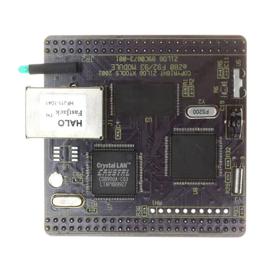
ZiLOG eZ80F92 Microcontroller Manuals
Manuals and User Guides for ZiLOG eZ80F92 Microcontroller. We have
2
ZiLOG eZ80F92 Microcontroller manuals available for free PDF download: User Manual
ZiLOG eZ80F92 User Manual (90 pages)
Brand:
ZiLOG
| Category:
Microcontrollers
| Size: 2 MB
Table of Contents
Safeguards
3
Table of Contents
5
List of Figures
7
Introduction
11
Kit Features
11
Hardware Specifications
12
Table 1. Ez80 ® Development Platform Hardware Specifications
12
Ez80 Development Platform Overview
13
Figure 1. Ez80 ® Development Platform Block Diagram with
14
Figure 3. the Ez80F92 Flash Module
16
Ez80 ® Development Platform
17
Functional Description
17
Figure 4. Basic Ez80
18
Figure 5. Physical Dimensions of the Ez80
19
Physical Dimensions
19
Operational Description
20
Ez80F92 Flash Module Interface
20
Figure 2. the Ez80
20
Figure 6. Ez80 ® Development Platform Peripheral Bus Connector Pin Configuration-JP1
21
Table 2. Ez80 ® Development Platform Peripheral Bus Connector Identification-JP1
22
Figure 7. Ez80 ® Development Platform I/O Connector Pin Configuration-JP2
26
Table 3. Ez80 ® Development Platform I/O Connector Identification-JP2
27
Application Module Interface
30
Table 4. GPIO Connector J6
31
I/O Functionality
33
Table 5. CPU Bus Connector J8
33
Table 6. LED and Port Emulation Addresses
34
Table 7. LED Anode/Gpio Port a Output Control Register
34
Table 8. GPIO Data Register
35
Table 9. Bit Access to the LED Cathode, Modem, and Triggers
36
Figure 8. Trigger Pins J21 and J22
37
Embedded Modem Socket Interface
38
Figure 9. Embedded Modem Socket Interface-J1, J5, and J9
38
Table 10. Connector J5
38
Table 11. Connector J9
39
Table 12. Connector J1
39
Ez80 ® Development Platform Memory
40
Figure 10. Memory Map of the Ez80
42
Leds
43
Push Buttons
43
Jumpers
44
Table 13. J2-Dis_Irda
44
Table 14. J3-DIS_EM
45
Table 15. J7-Flashwe (Off-Chip)
45
Table 16. J11-Dis_Flash (Off-Chip)
46
Table 17. J12-5VDC/3.3VDC for an Embedded Modem
46
Table 18. J14-RI
47
Table 19. J15-RS485_1_EN
47
Table 20. J16-RS485_2_EN
48
Table 21. J17-RT_1
48
Connectors
49
Table 22. J18-RT_2
49
Console
50
Modem
50
I 2 C Devices
50
Table 23. I 2 C Addresses
50
DC Characteristics
51
Table 24. DC Current Characteristics of the Ez80 ® Development Platform with Different Module Loads
51
Ez80F92 Flash Module
53
Functional Description
53
Physical Dimensions
54
Figure 11. Physical Dimensions of the Ez80F92 Flash Module
54
Figure 12. Ez80F92 Flash Module-Top Layer
55
Figure 13. Ez80F92 Flash Module-Bottom Layer
56
Operational Description
57
Ez80F92 Flash Module Memory
57
Reset Generator
58
Irda Transceiver
58
Figure 14. Irda Hardware Connections
59
DC Characteristics
61
Flash Loader Utility
61
Mounting the Module
61
Changing the Power Supply Plug
62
Figure 15. 9VDC Universal Power Supply Components
62
Figure 16. Inserting a New Plug Configuration
63
Zpakii
64
ZDI Target Interface Module
64
Jtag
64
Application Modules
64
Zdsii
66
Troubleshooting
67
Overview
67
Cannot Download Code
67
No Output on Console Port
67
Irda Port Not Working
68
Contacting Zilog Customer Support
68
Schematic Diagrams
69
Ez80 ® Development Platform
69
Figure 17. Ez80 ® Development Platform Schematic Diagram
70
Figure 21. Ez80 ® Development Platform Schematic Diagram
73
Ez80F92 Flash Module
74
Figure 22. Schematic Diagram, #1 of 9-Top Level
74
Figure 23. Schematic Diagram, #2 of 9-100-Pin QFP Ez80F92
75
Figure 24. Schematic Diagram, #3 of 9-36-Pin SRAM Device
76
Figure 25. Schematic Diagram, #4 of 9-NOR Flash Device
77
Figure 26. Schematic Diagram, #5 of 9-Ez80F92 Flash Module
78
Figure 27. Schematic Diagram, #6 of 9-Irda Reset
79
Figure 28. Schematic Diagram, #7 of 9-Headers
80
Figure 29. Schematic Diagram, #8 of 9-Power Supply
81
Figure 30. Schematic Diagram, #9 of 9-Control Logic
82
Appendix A . . . . . . . . . . . . . . . . . . . . . . . . . . . . . . . . . . . . . . . . . . . . . . . . . . 73 General Array Logic Equations
83
U10 Address Decoder
83
U15 Address Decoder
86
Customer Feedback Form
89
Advertisement
ZiLOG eZ80F92 User Manual (90 pages)
Brand:
ZiLOG
| Category:
Microcontrollers
| Size: 2 MB
Table of Contents
Safeguards
3
Table of Contents
5
List of Figures
7
Introduction
11
Kit Features
11
Hardware Specifications
12
Table 1. Ez80 ® Development Platform Hardware Specifications
12
Ez80 Development Platform Overview
13
Figure 1. Ez80 ® Development Platform Block Diagram with
14
Figure 2. the Ez80
15
Figure 3. the Ez80F92 Flash Module
16
Ez80 ® Development Platform
17
Functional Description
17
Figure 4. Basic Ez80
18
Physical Dimensions
19
Figure 5. Physical Dimensions of the Ez80
19
Operational Description
20
Ez80F92 Flash Module Interface
20
Table 2. Ez80 ® Development Platform Peripheral Bus Connector
24
Application Module Interface
30
Table 4. GPIO Connector J6
31
I/O Functionality
33
Table 5. CPU Bus Connector J8
33
Table 6. LED and Port Emulation Addresses
34
Table 7. LED Anode/Gpio Port a Output Control Register
34
Table 8. GPIO Data Register
35
Table 9. Bit Access to the LED Cathode, Modem, and Triggers
36
Figure 8. Trigger Pins J21 and J22
37
Embedded Modem Socket Interface
38
Figure 9. Embedded Modem Socket Interface-J1, J5, and J9
38
Table 10. Connector J5
38
Table 11. Connector J9
39
Table 12. Connector J1
39
Ez80 ® Development Platform Memory
40
Figure 10. Memory Map of the Ez80 ® Development Platform and
42
Leds
43
Push Buttons
43
Jumpers
44
Table 13. J2-Dis_Irda
44
Table 14. J3-DIS_EM
45
Table 15. J7-Flashwe (Off-Chip)
45
Table 16. J11-Dis_Flash (Off-Chip)
46
Table 17. J12-5VDC/3.3VDC for an Embedded Modem
46
Table 18. J14-RI
47
Table 19. J15-RS485_1_EN
47
Table 20. J16-RS485_2_EN
48
Table 21. J17-RT_1
48
Connectors
49
Table 22. J18-RT_2
49
Console
50
Modem
50
I 2 C Devices
50
Table 23. I 2 C Addresses
50
DC Characteristics
51
Table 24. DC Current Characteristics of the Ez80
51
Ez80F92 Flash Module
53
Functional Description
53
Physical Dimensions
54
Figure 11. Physical Dimensions of the Ez80F92 Flash Module
54
Figure 12. Ez80F92 Flash Module-Top Layer
55
Figure 13. Ez80F92 Flash Module-Bottom Layer
56
Operational Description
57
Ez80F92 Flash Module Memory
57
Reset Generator
58
Irda Transceiver
58
Figure 14. Irda Hardware Connections
59
DC Characteristics
61
Flash Loader Utility
61
Mounting the Module
61
Changing the Power Supply Plug
62
Figure 15. 9VDC Universal Power Supply Components
62
Figure 16. Inserting a New Plug Configuration
63
Zpakii
64
ZDI Target Interface Module
64
Jtag
64
Application Modules
64
Zdsii
66
Troubleshooting
67
Overview
67
Cannot Download Code
67
No Output on Console Port
67
Irda Port Not Working
68
Contacting Zilog Customer Support
68
Schematic Diagrams
69
Ez80 ® Development Platform
69
Ez80F92 Flash Module
74
Figure 22. Schematic Diagram, #1 of 9-Top Level
74
Figure 23. Schematic Diagram, #2 of 9-100-Pin QFP Ez80F92
75
Figure 24. Schematic Diagram, #3 of 9-36-Pin SRAM Device
76
Figure 25. Schematic Diagram, #4 of 9-NOR Flash Device
77
Figure 26. Schematic Diagram, #5 of 9-Ez80F92 Flash Module
78
Figure 27. Schematic Diagram, #6 of 9-Irda Reset
79
Figure 28. Schematic Diagram, #7 of 9-Headers
80
Figure 29. Schematic Diagram, #8 of 9-Power Supply
81
Figure 30. Schematic Diagram, #9 of 9-Control Logic
82
General Array Logic Equations
83
U10 Address Decoder
83
U15 Address Decoder
86
Customer Feedback Form
89
Advertisement
Related Products
ZiLOG Zdots eZ80AcclaimPlus
ZiLOG eZ80L92
ZiLOG EZ80F920200ZCO
ZiLOG EZ80L920210ZCO
ZiLOG eZ80F91
ZiLOG eZ80
ZiLOG eZ8
ZiLOG eZ80Acclaim!
ZiLOG C84 ICEBOX
ZiLOG ICEBOX Z86L98
ZiLOG Categories
Microcontrollers
Computer Hardware
Motherboard
Cables and connectors
Desktop
More ZiLOG Manuals
Login
Sign In
OR
Sign in with Facebook
Sign in with Google
Upload manual
Upload from disk
Upload from URL