Sign In
Upload
Manuals
Brands
YASKAWA Manuals
Servo Drives
SGDM
YASKAWA SGDM AC Servo Drives Manuals
Manuals and User Guides for YASKAWA SGDM AC Servo Drives. We have
2
YASKAWA SGDM AC Servo Drives manuals available for free PDF download: User Manual
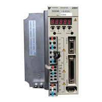
YASKAWA SGDM User Manual (578 pages)
AC Servo Drives
Brand:
YASKAWA
| Category:
Servo Drives
| Size: 15 MB
Table of Contents
Table of Contents
13
1 Outline
24
Checking Products
25
Check Items
25
Servomotors
25
Servopacks
26
Product Part Names
27
Servomotors
27
Servopacks
29
Examples of Servo System Configurations
31
Single-Phase, 100 V and 200 V Main Circuit
31
Three-Phase, 200 V Main Circuit
32
Connecting to SGMCS Servomotor
33
Applicable Standards
34
North American Safety Standards (UL, CSA)
34
CE Marking
34
Σ-II Series SGDM SERVOPACK Upgraded Functions
35
2 Selections
37
Servomotor Model Designations
38
Model SGMAH (3000 Min -1 )
38
Model SGMPH (3000 Min -1 )
40
Model SGMGH (1500 Min -1 )
44
Model SGMGH (1000 Min -1 )
44
Model SGMGH (1000 Min )
44
Model SGMSH (3000 Min -1 )
46
Model SGMDH (2000 Min -1 )
48
Model SGMCS
49
SERVOPACK Model Designations
50
Σ-II Series Servopacks and Applicable Servomotors
51
SGDM Servopacks and SGM H Servomotors
51
SGDM Servopacks and SGMCS Servomotors
52
Selecting Cables
53
Cables for SGMAH and SGMPH Servomotors
53
Cables for SGMGH/SGMSH/SGMDH Servomotors
56
Cables for SGMCS Servomotors
59
Selecting Peripheral Devices
62
Special Options
62
Molded-Case Circuit Breaker and Fuse Capacity
64
Noise Filters, Magnetic Conductors, Surge Absorbers and DC Reactors
65
Regenerative Resistors and Brake Power Supply Units
66
3 Servomotor Specifications and Dimensional Drawings
68
Ratings and Specifications of SGMAH
70
SGMAH Servomotors Without Gears
70
Ratings and Specifications of SGMAH
71
SGMAH Servomotors with Standard Backlash Gears
72
SGMAH Servomotors with Low-Backlash Gears
74
Ratings and Specifications of SGMPH
76
SGMPH Servomotors Without Gears
76
SGMPH Servomotors with Standard Backlash Gears
79
SGMPH Servomotors with Low-Backlash Gears
80
Ratings and Specifications of SGMGH
81
Ratings and Specifications of SGMGH
83
Ratings and Specifications of SGMSH
93
Ratings and Specifications of SGMDH
97
SGMDH Servomotors
97
Ratings and Specifications of SGMCS Servomotors
99
Small-Capacity Series SGMCS Servomotors
99
Middle-Capacity Series SGMCS Servomotors
102
Mechanical Specifications of SGMAH, SGMPH, SGMGH, SGMSH, and SGMDH Servomotors
104
Servomotors
104
Precautions on Servomotor Installation
104
Mechanical Tolerance
105
Direction of Servomotor Rotation
105
Impact Resistance
106
Vibration Resistance
106
Allowable Loads
107
Mechanical Specifications of SGMCS Servomotors
107
Direction of Servomotor Rotation
108
Mechanical Tolerance
108
Enclosure
109
Heating Conditions
109
Impact Resistance
109
Vibration Class
109
Vibration Resistance
109
Terms and Data for Servomotors with Gears
110
Servomotor Dimensional Drawings
112
Dimensional Drawings of SGMAH Servomotors
113
Dimensional Drawings of SGMPH Servomotors
132
SGMPH Servomotors
132
And Without Brakes
136
Dimensional Drawing of Output Shafts with Oil Seals for SGMAH and SGMPH Servomotors
145
SGMAH Servomotors
145
SGMPH Servomotors
145
Dimensional Drawings of SGMGH Servomotors
146
Servomotors
146
With Brakes
148
SGMGH Servomotors
155
SGMGH Servomotors
161
SGMGH Servomotors (1500 Min Brakes (Flange-Mounted Type)
161
Dimensional Drawings of SGMGH Servomotors
164
With Standard Backlash Gears and
169
With Standard Backlash Gears and
174
With Low-Backlash Gears and Without
179
Dimensional Drawings of SGMDH Servomotors
190
SGMCS Servomotors Φ135 Model
192
SGMCS Servomotors Φ175 Model
193
SGMCS Servomotors Φ230 Model
194
SGMCS Servomotors Φ290 Model
195
SGMCS Servomotors Φ280 Model
196
SGMCS Servomotors Φ360 Model
197
Shaft End Specifications for SGMGH, SGMSH and SGMDH Servomotors
201
SGMSH Servomotors
203
SGMDH Servomotors
204
Advertisement
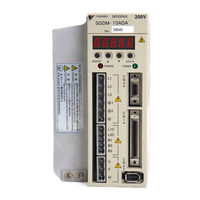
YASKAWA SGDM User Manual (341 pages)
AC Servo Drives
Brand:
YASKAWA
| Category:
Servo Drives
| Size: 18 MB
Table of Contents
Table of Contents
14
1 Outline
21
Checking Products
22
Check Items
22
Servomotors
22
Servopacks
22
Examples of Servo System Configurations
23
Three-Phase, 200 V Series
23
Three-Phase, 400 V Series
24
Applicable Standards
25
North American Safety Standards (UL)
25
CE Marking
25
2 Selections
26
Servomotor Model Designations
27
SERVOPACK Model Designations
28
Σ-II Series Servopacks and Applicable Servomotor
29
Selecting Cables
30
Cables for SGMVH Servomotor
30
Selecting Peripheral Devices
31
Special Options
31
Molded-Case Circuit Breaker and Fuse Capacity
33
Noise Filters, Magnetic Contactors, and Brake Power Supply Units
34
Regenerative Resistor Units
34
Dynamic Brake (DB) Units
35
Thermal Relays
36
3 Servomotor Specifications and Dimensional Drawings
37
Ratings and Specifications of SGMVH (1500 Min -1 )
38
Ratings and Specifications of SGMVH (800 Min -1 )
43
Mechanical Specifications of Servomotors
45
Precautions on Servomotor Installation
45
Allowable Radial and Thrust Loads
49
Mechanical Tolerance
50
Direction of Servomotor Rotation
50
Impact Resistance
50
Vibration Resistance
50
Vibration Class
51
Dimensional Drawings of SGMVH Servomotors (1500 Min -1 )
58
Dimensional Drawings of SGMVH Servomotors (800 Min -1 )
61
4 SERVOPACK Specifications and Dimensional Drawings
62
SERVOPACK Ratings and Specifications
63
SERVOPACK Ratings and Specifications
64
SERVOPACK Installation
66
SERVOPACK Internal Block Diagrams
68
Three-Phase 200 V, 22 Kw, 30 Kw Models
68
Three-Phase 200 V, 37 Kw Model
69
Three-Phase 400 V, 22 Kw, 30 Kw Models
70
Three-Phase 400 V, 37 Kw Model
70
Three-Phase 400 V, 45 Kw, 55 Kw Models
71
Three-Phase 400 V, 90 Kw Model
71
Servopack's Power Supply Capacities and Power Losses
72
SERVOPACK Overload Characteristics and Allowable Load Moment of Inertia
73
Overload Characteristics
73
Starting and Stopping Time
74
Load Moment of Inertia
75
SERVOPACK Dimensional Drawings
77
Three-Phase 200 V, 22 Kw, 30 Kw Models
77
Three-Phase 200 V, 37 Kw Model
78
Three-Phase 400 V, 22 Kw Model
79
Three-Phase 400 V, 30 Kw Model
80
Three-Phase 400 V, 37 Kw Model
81
Three-Phase 400 V, 45 Kw, 55 Kw Models
81
Three-Phase 400 V, 90 Kw Model
82
5 Specifications and Dimensional Drawings of Cables and Peripheral Devices
83
SERVOPACK Main Circuit Wire Size
84
Wiring Cables to Main Circuit Terminals
84
Three-Phase 200
85
Three-Phase 400
86
Encoder Cables for CN2 Connector
88
Encoder Cable with Connectors on both Ends
88
Cable with Loose Wire at Encoder End
89
Connectors and Cables for Encoder Signals
90
I/O Signal Cables for CN1 Connector
92
Connector Type and Cable Size
92
Connection Diagram
94
Peripheral Devices
95
Cables for Connecting Personal Computers
95
Digital Operator
96
Cables for Analog Monitor
97
Connector Terminal Block Converter Unit
98
Brake Power Supply Unit
99
Absolute Encoder Battery
100
Molded-Case Circuit Breaker (MCCB)
101
Noise Filter
102
Surge Absorber
104
Regenerative Resistor Unit
105
Dynamic Brake (DB) Unit
111
Thermal Relays
118
Variable Resistor for Speed and Torque Setting
121
Encoder Signal Converter Unit
122
MECHATROLINK Application Module
123
Devicenet Application Module
124
PROFIBUS-DP Application Module
125
Fully-Closed Application Module
126
6 Wiring
127
Wiring Main Circuit
128
Names and Functions of Main Circuit Terminals
128
Typical Main Circuit Wiring Examples
130
Wiring Encoders
134
Connecting an Encoder (CN2) and Output Signals from the SERVOPACK (CN1)
134
Encoder Connector (CN2) Terminal Layout
135
I/O Signal Connections
136
Example of I/O Signal Connection
136
I/O Signal Connector (CN1) Terminal Layout
137
I/O Signal (CN1) Names and Functions
138
Interface Circuit
140
Others
143
Wiring Precautions
143
Wiring for Noise Control
144
Using more than One SERVOPACK
148
7 Digital Operator/Panel Operator
152
Functions on Digital Operator/Panel Operator
152
Connecting the Digital Operator
152
Key Names and Functions
153
Basic Mode Selection and Operation
154
Status Display
155
Operation in Utility Function Mode (Fn )
157
List of Utility Function Modes
157
Alarm Traceback Data Display (Fn000)
158
Zero-Point Search Mode (Fn003)
159
Parameter Settings Initialization (Fn005)
160
Alarm Traceback Data Clear (Fn006)
161
Manual Zero Adjustment and Gain Adjustment of Analog Monitor Output (Fn00C, Fn00D)
162
Offset Adjustment of Motor Current Detection Signal (Fn00E, Fn00F)
165
Password Setting (Protects Parameters from Being Changed) (Fn010)
167
Motor Models Display (Fn011)
168
Software Version Display (Fn012)
169
Application Module Detection Results Clear (Fn014)
170
Operation in Parameter Setting Mode (Pn )
171
Setting Parameters
171
Input Circuit Signal Allocation
174
Output Circuit Signal Allocation
177
Operation in Monitor Mode (un )
179
List of Monitor Modes
179
8 Operation
183
Trial Operation
186
Trial Operation for Servomotor Without Load
188
Trial Operation for Servomotor Without Load from Host Reference
197
Trial Operation with the Servomotor Connected to the Machine
197
Servomotor with Brakes
198
Position Control by Host Controller
198
Control Mode Selection
199
Setting Common Basic Functions
200
Setting the Servo on Signal
200
Switching the Servomotor Rotation Direction
201
Setting the Overtravel Limit Function
202
Setting for Holding Brakes
204
Selecting the Stopping Method after Servo off
208
Instantaneous Power Loss Settings
209
Absolute Encoders
210
Interface Circuits
211
Selecting an Absolute Encoder
212
Handling Batteries
212
Replacing Batteries
213
Absolute Encoder Setup (Fn008)
214
Absolute Encoder Reception Sequence
215
Multiturn Limit Setting
218
Multiturn Limit Setting When Multiturn Limit Disagreement (A.CC) Occurred
219
Operating Using Speed Control with Analog Reference
220
Setting Parameters
220
Setting Input Signals
221
Adjusting Offset
222
Soft Start
225
Speed Reference Filter
225
Using the Zero Clamp Function
225
Encoder Signal Output
227
Speed Coincidence Output
230
Operating Using Position Control
231
Setting Parameters
231
Setting the Electronic Gear
233
Operating Using Position Control
233
Position Reference
236
Smoothing
239
Positioning Completed Output Signal
240
Positioning Near Signal
241
Reference Pulse Inhibit Function (INHIBIT)
242
Reference Pulse Input Multiplication Switching Function
243
Operating Using Torque Control
245
Setting Parameters
245
Torque Reference Input
245
Adjusting the Reference Offset
246
Limiting Servomotor Speed During Torque Control
248
Operating Using Speed Control with an Internally Set Speed
250
Setting Parameters
250
Input Signal Settings
251
Operating Using an Internally Set Speed
251
Limiting Torque
253
Internal Torque Limit (Limiting Maximum Output Torque)
253
External Torque Limit (Output Torque Limiting by Input Signals)
254
Torque Limiting Using an Analog Voltage Reference
255
Torque Limiting Using an External Torque Limit and Analog Voltage Reference
256
Checking Output Torque Limiting During Operation
257
Control Mode Selection
258
Setting Parameters
258
Switching the Control Mode
258
Servo Alarm Output (ALM) and Alarm Code Output (ALO1, ALO2, ALO3)
259
Warning Output (/WARN)
260
Servomotor Running Output Signal (/TGON)
260
Servo Ready (/S-RDY) Output
261
9 Adjustments
263
Autotuning
263
Servo Gain Adjustment Methods
263
List of Servo Adjustment Functions
263
Online Autotuning
265
Manual Tuning
265
Explanation of Servo Gain
265
Servo Gain Manual Tuning
266
Position Loop Gain
266
Speed Loop Gain
267
Speed Loop Integral Time Constant
267
Servo Gain Adjustment Functions
268
Feed-Forward Reference
268
Torque Feed-Forward
268
Speed Feed-Forward
269
Proportional Control Operation (Proportional Operation Reference)
270
Using the Mode Switch (P/PI Switching)
271
Setting the Speed Bias
274
Speed Feedback Filter
274
Speed Feedback Compensation
274
Switching Gain Settings
275
Torque Reference Filter
277
Analog Monitor
281
10 Inspection, Maintenance, and Troubleshooting
283
Alarm Display Table
284
Troubleshooting
284
Warning Display
286
Alarm Display Table When the Application Module Is Used
287
Warning Display Table When the Application Module Is Used
288
Troubleshooting of Alarm and Warning
289
Troubleshooting for Malfunction Without Alarm Display
298
Inspection and Maintenance
302
Servomotor Inspection
302
SERVOPACK Inspection
302
Servopack's Parts Replacement Schedule
303
11 Appendix
304
Selection Example for Speed Control
305
Selection Example for Position Control
307
Connection to Host Controller
310
Example of Connection to MP2200/MP2300 Motion Module SVA-01
310
Example of Connection to MP920 4-Axes Analog Module SVA-01
311
Example of Connection to Omron's Motion Control Unit
312
Example of Connection to Omron's Position Control Unit
313
Example of Connection to Mitsubishi's AD72 Positioning Unit
314
Unit (SERVOPACK in Speed Control Mode)
314
Example of Connection to Mitsubishi's AD75 Positioning Unit (SERVOPACK in Position Control Mode)
315
List of Parameters
316
Utility Functions List
316
List of Parameters
317
Parameter Recording Table
332
Index
335
Revision History
339
Advertisement
Related Products
YASKAWA SGDM Series
YASKAWA SGDM-2BADB
YASKAWA SGDM-3ZADB
YASKAWA SGDM-3GADB
YASKAWA SGDM SERVOPACK
YASKAWA SGD7S-7R6A
YASKAWA SGD7S-7R6A20A023F40B
YASKAWA SGDV-J Series
YASKAWA SGDS-B Series
YASKAWA SGDV-1R6A
YASKAWA Categories
Controller
DC Drives
Servo Drives
Robotics
Inverter
More YASKAWA Manuals
Login
Sign In
OR
Sign in with Facebook
Sign in with Google
Upload manual
Upload from disk
Upload from URL