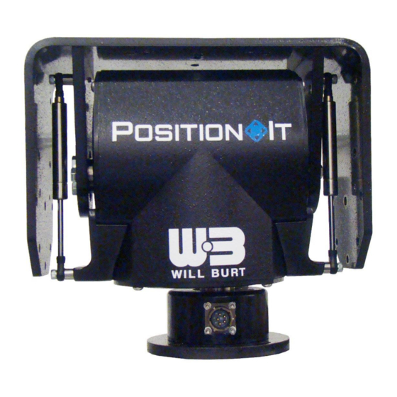
Sign In
Upload
Manuals
Brands
Will Burt Manuals
Controller
PositionIt PI-150
Will Burt PositionIt PI-150 Manuals
Manuals and User Guides for Will Burt PositionIt PI-150. We have
2
Will Burt PositionIt PI-150 manuals available for free PDF download: Operator's Manual
Will Burt PositionIt PI-150 Operator's Manual (68 pages)
Brand:
Will Burt
| Category:
Valve Positioners
| Size: 5.68 MB
Table of Contents
Table of Contents
5
Section 1 Introduction
11
Safety Precautions
11
How this Manual Is Organized
11
Additional Documentation
12
Definitions of Terms and Symbols
12
Figure 1-1 Home Position (PI-150 Shown)
12
Figure 1-2 Positioner Directions (PI-150 Shown)
13
Specifications
14
Table 1-1 Positioner Specifications
14
Table 1-2 Default Joystick Controller (P/N: 5098901) Specifications
14
Major Components
15
Positioner
15
Figure 1-3 Positioners
15
Controller
16
Figure 1-4 Default Joystick Controller
16
Power/Data Cable
17
Figure 1-5 Power/Data Cable
17
Table 1-3 Standard Cables
17
Positioner Power Supply
18
Step up Converter
18
Figure 1-6 Positioner Power Supply
18
Figure 1-7 Step up Converter
18
Step down Converter
19
Barrel Connector (2.1 MM)
19
Quick Overview
20
Section 2 Installation
21
Pre-Installation Check
21
Installation Tools
22
Components
22
Unpacking
22
Table 2-1 Tools and Materials Recommended for Installation
22
Mounting the Positioner
23
Figure 2-1 Rear of Positioner (PI-150 Shown)
23
Figure 2-2 Positioner Mounting Hole Pattern
23
Wiring the System
24
Positioner Plugs
24
Figure 2-3 Positioner Plug Locations (PI-150 Shown)
24
Figure 2-4 Carefully Pull out the Removable Plug, Gasket, and Attached Wires
25
Figure 2-5 Quick Connect
25
Figure 2-6 Remove the (4) Bolts Securing the Plug Plate
26
Figure 2-7 Remove Plug Plate and Gasket
26
Figure 2-8 Pull the Wires out the Bottom of the Positioner
27
Figure 2-9 Secure the Gasket and Removable Plug to the Bottom Egress
27
Connecting Power and Controls
28
Figure 2-10 Secure the Plug Plate and Gasket to the Side Egress
28
Figure 2-11 Powered with 12 VDC
29
Figure 2-12 Powered with 24 VDC
30
Figure 2-13 Powered with VAC
31
Mounting the Payload
32
Figure 2-14 PI-150 Payload Mounting Hole Pattern
32
Figure 2-15 PI-75 Payload Mounting Hole Pattern
32
Setting Presets and Electronic Limit Stops
33
Section 3 Operation
35
Pre-Operation Check
35
Operation Tools
36
General Controls
36
Table 3-1 Tools and Materials Recommended for Operation
36
Keyboard
37
Joystick
37
Figure 3-1 Keyboard Keys
37
Menu Functions
38
Figure 3-2 Menu Screen
38
Presets
39
Setting Presets with the Keyboard
39
Recalling Presets with the Keyboard
39
Electronic Limit Stops
40
Adjust Limit Stops with the Keyboard
40
Table 3-2 Limit Stop Adjustment Numbers
40
Restore Limit Stops with the Keyboard
41
Unstowing the Positioner
41
Table 3-3 Default Limit Stop Numbers
41
Stowing the Positioner
42
Transportation
42
Section 4 Maintenance
43
Routine Maintenance
43
Replacement Parts
43
Section 5 Troubleshooting
45
Troubleshooting Guide
45
Table 5-1 Troubleshooting the Positioner
45
Table 5-2 Troubleshooting the Controller
46
Restoring Factory Defaults
47
Camid
47
Monid
47
Figure 5-1 Start up Screen
47
Protocol
48
Figure 5-2 Menu Screen
48
Figure 5-3 Protocol Setup Screen
48
Figure 5-4 Dome Screen
48
Table 5-3 Resetting the Protocol
48
Baud Rate
49
Figure 5-5 Keyboard Setup Screen
49
Table 5-4 Resetting the Baud Rate
49
Section 6 Appendix
51
Communications Bridge Board Interface (Optional)
51
Electrical Connections
51
Wire the Bridge Board Interface
51
Figure 6-1 Contact Closure
52
Table 6-1 Contact Closure Wires
52
Set Stow and Unstow
53
With a Push Button Controller
53
With a Toggle Switch Controller
53
Panel Mount Controller Assembly (Optional)
54
Figure 6-2 Panel Mount Controller (P/N: 4270601)
54
Section 7 Drawings
55
Advertisement
Will Burt PositionIt PI-150 Operator's Manual (32 pages)
RACKMOUNT CONTROLLER
Brand:
Will Burt
| Category:
Controller
| Size: 1.16 MB
Table of Contents
Table of Contents
5
Safety Summary
7
Signal Word Definitions
7
General Safety Instructions
7
Symbols
8
Section 1 Introduction & Intended Use
9
Specification Compliance
9
Safety Precautions
9
Manual Organization
9
Additional Documentation
10
Specifications
11
Figure 1-1 Front Panel - Rackmount Controller
11
Figure 1-2 Back - Rackmount Controller
11
Table 1-1 Positionit Rackmount Controller Specifications
11
Section 2 Installation
13
Pre-Installation Check
13
Physical Installation
14
Figure 2-1 Rackmount Controller Dimensions (2U - 19")
14
Components
15
Unpacking
15
Power and Controls System Overview
15
Typical System Setup
16
Figure 2-2 Typical System Setup
16
System Wiring
17
Data Input Connectors
17
Figure 2-3 Data Input Connectors
17
Table 2-1 Data Input Connectors
17
Power Input and Power/Data Output Connectors
18
Figure 2-4 Power Input & Power/Data Output Connectors
18
Table 2-2 Power Input & Power/Data Output Connectors
18
Discrete Input and Output Connectors
19
Figure 2-5 Discrete Input & Output Connectors
19
Figure 3-7 Discrete Outputs
19
Table 2-3 Discrete Input & Output Table
19
I/O Map
20
Positioner/Auxiliary Switch - "Positioner
20
Figure 2-6 Control Configuration - "Positioner" Position
20
Positioner/Auxiliary Switch - "Aux
21
Figure 2-7 Control Configuration - "Aux" Position
21
Section 3 Operation
23
Pre-Operation Check
23
Switching on the System
23
Figure 3-1 Power Switch
23
Push-Button Control
24
Figure 3-2 Push-Button Controls
24
Stowing and Unstowing the Positioner
25
Figure 3-3 Stow/Unstow Push-Button Controls
25
Alternate Positioner Control Options
26
Figure 3-4 Data Input Controls
26
Figure 3-5 Back - Discrete Input Controls
26
Table 3-1 Pelco D Auxiliary Command List
26
Positioner/Auxiliary Switch
27
Stow Confirmation & Optional I/O Interlock
27
Figure 3-6 Front Panel
27
Digital Discrete Outputs
28
LCD Display - Home Screen
28
Positioner Address
28
Figure 3-8 Home Screen - LCD Display
28
Limit Stop Reached Notification
29
Preset Designation
29
Pan/Tilt Position Feedback
29
Pan/Tilt Speed Feedback
29
LCD Display - Selector Menu
30
Address Select
30
Degrees or Radians
30
Zero Home Position
30
Setting & Clearing Electronic Limit Stops
30
Setting, Calling and Clearing Presets
31
Setting Max Pan and Tilt Speed
31
LCD Display Back Light Brightness
31
Setting Baud Rate
31
Advertisement
Related Products
Will Burt PositionIt PI-75
Will Burt Position It RACK MOUNT CONTROLLER
Will Burt PositionIt PI-35
Will Burt Inflexion Plus 1.8
Will Burt Inflexion Plus 2.3
Will Burt Inflexion Plus 3.0
Will Burt Inflexion Plus 4.5
Will Burt Inflexion Plus 6.0
Will Burt Inflexion Plus 7.5
Will Burt POSITIONIT MM233TX2TXRX2
Will Burt Categories
Lighting Equipment
Antenna
Air Compressor
Valve Positioners
Racks & Stands
More Will Burt Manuals
Login
Sign In
OR
Sign in with Facebook
Sign in with Google
Upload manual
Upload from disk
Upload from URL