
Related Manuals for WAGO 750-652


Summary of Contents for WAGO 750-652
- Page 1 WAGO-I/O-SYSTEM 750 Manual 750-652 Serial Interface RS-232 / RS-485 Configurable Version 1.4.0...
- Page 2 WAGO-I/O-SYSTEM 750 750-652 Serial Interface RS-232 / RS-485 © 2015 by WAGO Kontakttechnik GmbH & Co. KG All rights reserved. WAGO Kontakttechnik GmbH & Co. KG Hansastraße 27 D-32423 Minden Phone: +49 (0) 571/8 87 – 0 Fax: +49 (0) 571/8 87 – 1 69 E-Mail: info@wago.com...
-
Page 3: Table Of Contents
2.1.1 Subject to Changes ................10 2.1.2 Personnel Qualifications ..............10 2.1.3 Use of the WAGO-I/O-SYSTEM 750 in Compliance with Underlying Provisions ................... 10 2.1.4 Technical Condition of Specified Devices ......... 11 Safety Advice (Precautions) ..............12 Device Description ..................14 View ...................... - Page 4 Table of Contents WAGO-I/O-SYSTEM 750 750-652 Serial Interface RS-232 / RS-485 5.1.4 RS-485 Operating Mode..............36 5.1.5 RS-422 Operating Mode..............36 5.1.6 DMX Operating Mode ............... 36 Data Exchange Operating Mode ............. 37 Mounting ..................... 38 Mounting Sequence ................. 38 Inserting and Removing Devices ............
- Page 5 WAGO-I/O-SYSTEM 750 Table of Contents 750-652 Serial Interface RS-232 / RS-485 10.2.1 Special Conditions for Safe Use (ATEX Certificate TÜV 07 ATEX 554086 X) ........68 10.2.2 Special Conditions for Safe Use (ATEX Certificate TÜV 12 ATEX 106032 X) ........69 10.2.3...
-
Page 6: Notes About This Documentation
Documentation Validity for Variants Unless otherwise indicated, the information given in this documentation applies to listed variants. The I/O module 750-652 shall only be installed and operated according to the instructions in this manual and in the manual for the used fieldbus coupler/controller. -
Page 7: Symbols
WAGO-I/O-SYSTEM 750 Notes about this Documentation 750-652 Serial Interface RS-232 / RS-485 Symbols Personal Injury! Indicates a high-risk, imminently hazardous situation which, if not avoided, will result in death or serious injury. Personal Injury Caused by Electric Current! Indicates a high-risk, imminently hazardous situation which, if not avoided, will result in death or serious injury. - Page 8 Notes about this Documentation WAGO-I/O-SYSTEM 750 750-652 Serial Interface RS-232 / RS-485 Additional Information: Refers to additional information which is not an integral part of this documentation (e.g., the Internet). Manual Version 1.4.0...
-
Page 9: Number Notation
WAGO-I/O-SYSTEM 750 Notes about this Documentation 750-652 Serial Interface RS-232 / RS-485 Number Notation Table 2: Number Notation Number Code Example Note Decimal Normal notation Hexadecimal 0x64 C notation Binary '100' In quotation marks, nibble separated with '0110.0100' dots (.) -
Page 10: Important Notes
2.1.1 Subject to Changes WAGO Kontakttechnik GmbH & Co. KG reserves the right to provide for any alterations or modifications that serve to increase the efficiency of technical progress. WAGO Kontakttechnik GmbH & Co. KG owns all rights arising from the granting of patents or from the legal protection of utility patents. -
Page 11: Technical Condition Of Specified Devices
Important Notes 750-652 Serial Interface RS-232 / RS-485 Appropriate housing (per 94/9/EG) is required when operating the WAGO-I/O- SYSTEM 750 in hazardous environments. Please note that a prototype test certificate must be obtained that confirms the correct installation of the system in a housing or switch cabinet. -
Page 12: Safety Advice (Precautions)
Install the device only in appropriate housings, cabinets or in electrical operation rooms! The WAGO-I/O-SYSTEM 750 and its components are an open system. As such, install the system and its components exclusively in appropriate housings, cabinets or in electrical operation rooms. Allow access to such equipment and fixtures to authorized, qualified staff only by means of specific keys or tools. - Page 13 WAGO-I/O-SYSTEM 750 Important Notes 750-652 Serial Interface RS-232 / RS-485 Do not use any contact spray! Do not use any contact spray. The spray may impair contact area functionality in connection with contamination. Do not reverse the polarity of connection lines! Avoid reverse polarity of data and power supply lines, as this may damage the devices involved.
-
Page 14: Device Description
750-652 Serial Interface RS-232 / RS-485 Device Description The I/O module 750-652 (Serial Interface RS-232 / RS-485) allows the optional connection of devices with a RS-485, RS-422 or RS-232 interface. It also provides gateways between the serial interface and the fieldbus systems supported by the WAGO-I/O-SYSTEM 750. - Page 15 The meaning of the LEDs is described in the “Display Elements” section. The I/O module 750-652 (Serial Interface RS-232 / RS-485) receives the 24 V voltage supply for the field level from an upstream I/O module or from the fieldbus coupler/controller via blade-formed power jumper contacts.
-
Page 16: Table 4: Compatibility List 750-0652
Device Description WAGO-I/O-SYSTEM 750 750-652 Serial Interface RS-232 / RS-485 The 750-652 module can be used with the fieldbus couplers and controllers of the WAGO-I/O-SYSTEM 750 of the specified version or higher listed in the “Compatibility list” table. Table 4: Compatibility List 750-0652... - Page 17 WAGO-I/O-SYSTEM 750 Device Description 750-652 Serial Interface RS-232 / RS-485 Table 4: Compatibility List 750-0652 Fieldbus Firmware Bus System Item No. couplers/controllers status Programmable 750-837 fieldbus controller 750-838 I/O-IPC 758-870/ 000-112 758-875/ 000-112 Programmable 750-849 fieldbus controller BACnet Programmable 750-830...
-
Page 18: View
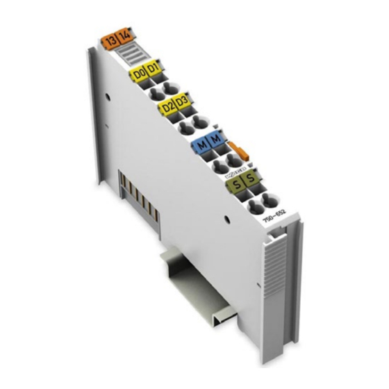
Device Description WAGO-I/O-SYSTEM 750 750-652 Serial Interface RS-232 / RS-485 View Figure 1: View Table 5: Legend for Figure “View” Pos. Description Details See Section Marking possibility with Mini- Status LEDs “Device Description” > “Display Elements” Data contacts “Device Description” > “Connectors”... -
Page 19: Connectors
WAGO-I/O-SYSTEM 750 Device Description 750-652 Serial Interface RS-232 / RS-485 Connectors 3.2.1 Data Contacts/Internal Bus Communication between the fieldbus coupler/controller and the I/O modules as well as the system supply of the I/O modules is carried out via the internal bus. It is comprised of 6 data contacts, which are available as self-cleaning gold spring contacts. -
Page 20: Power Jumper Contacts/Field Supply
The blade contacts are sharp-edged. Handle the I/O module carefully to prevent injury. The I/O module 750-652 has 2 self-cleaning power jumper contacts that supply and transmit power for the field side. The contacts on the left side of the I/O module are designed as blade contacts and those on the right side as spring contacts. - Page 21 WAGO-I/O-SYSTEM 750 Device Description 750-652 Serial Interface RS-232 / RS-485 Use supply modules for ground (earth)! The I/O module has no power jumper contacts for receiving and transmitting the earth potential. Use a supply module when an earth potential is needed for the subsequent I/O modules.
-
Page 22: Cage Clamp
Device Description WAGO-I/O-SYSTEM 750 750-652 Serial Interface RS-232 / RS-485 ® 3.2.3 CAGE CLAMP Connectors Use shielded signal lines! Only use shielded signal lines for analog signals and I/O modules which are equipped with shield clamps. Only then can you ensure that the accuracy and interference immunity specified for the respective I/O module can be achieved even in the presence of interference acting on the signal cable. -
Page 23: Display Elements
WAGO-I/O-SYSTEM 750 Device Description 750-652 Serial Interface RS-232 / RS-485 Display Elements Figure 5: Display Elements Table 8: Legend for Figure “Display Elements” Designation Status Function Ready for operation and undisturbed internal bus Green communication Function Not ready for operation or no or disturbed internal bus... -
Page 24: Operating Elements
Defective characters are not transmitted by the I/O module to the fieldbus coupler/controller. RTS/CTS data flow control active Firmware version 03 or higher Operating Elements The I/O module 750-652 has no operating elements. Schematic Diagram Figure 6: Schematic Diagram Manual... -
Page 25: Technical Data
WAGO-I/O-SYSTEM 750 Device Description 750-652 Serial Interface RS-232 / RS-485 Technical Data 3.6.1 Device Data Table 9: Technical Data ‒ Device Data Width 12 mm Height (from upper edge of DIN 35 rail) 64 mm Length 100 mm Weight approx. 50 g... -
Page 26: Interface
Device Description WAGO-I/O-SYSTEM 750 750-652 Serial Interface RS-232 / RS-485 3.6.4 Interface Table 12: Technical Data ‒ Interface Number of interfaces Input resistance of the receiver 24 kΩ (1/2 Unit Load) RS-485/RS-422 Defined receiver state with short- circuited or isolated inputs... -
Page 27: Approvals
Ex nA IIC T4 Gc Ex tc IIIC T135°C Dc ANSI/ISA 12.12.01 Class I, Div2 ABCD T4 The following ship approvals have been granted to 750-652 I/O modules: ABS (American Bureau of Shipping) Federal Maritime and Hydrographic Agency BV (Bureau Veritas) -
Page 28: Standards And Guidelines
LR (Lloyd’s Register) Env. 1, 2, 3, 4 NKK (Nippon Kaiji Kyokai) RINA (Registro Italiano Navale) The following ship approvals have been granted to 750-652/025-000 I/O module variations: Federal Maritime and Hydrographic Agency GL (Germanischer Lloyd) Cat. A, B, C, D (EMC 1) -
Page 29: Process Image
WAGO-I/O-SYSTEM 750 Process Image 750-652 Serial Interface RS-232 / RS-485 Process Image Mapping of process data in the process image of fieldbus systems The representation of the I/O modules’ process data in the process image depends on the fieldbus coupler/controller used. Please take this information as well as the particular design of the respective control/status bytes from the section “Fieldbus... -
Page 30: Table 18: Control Byte C0
Process Image WAGO-I/O-SYSTEM 750 750-652 Serial Interface RS-232 / RS-485 Table 18: Control Byte C0 Bit 7 Bit 6 Bit 5 Bit 4 Bit 3 Bit 2 Bit 1 Bit 0 Transmit request Receive acknowledge Initialization request Send continuous (of data from the FIFO) -
Page 31: Data Exchange Mode
WAGO-I/O-SYSTEM 750 Process Image 750-652 Serial Interface RS-232 / RS-485 Table 21: Status Byte S1 Bit 7 Bit 6 Bit 5 Bit 4 Bit 3 Bit 2 Bit 1 Bit 0 BUF_E Input length (number of characters received that are available in the input data,... -
Page 32: Table 23: Control Byte C0
Process Image WAGO-I/O-SYSTEM 750 750-652 Serial Interface RS-232 / RS-485 Table 23: Control Byte C0 Bit 7 Bit 6 Bit 5 Bit 4 Bit 3 Bit 2 Bit 1 Bit 0 Initialization/reset (If the bit is set, the module is in the reset state. -
Page 33: Function Description
WAGO-I/O-SYSTEM 750 Function Description 750-652 Serial Interface RS-232 / RS-485 Function Description Operating Modes for Serial Transmission In den In the operating modes for serial transmission, the I/O module allows communication with serial devices via RS-232, RS-485, RS-422 or DMX. -
Page 34: Receive Data
Function Description WAGO-I/O-SYSTEM 750 750-652 Serial Interface RS-232 / RS-485 interface according to time criteria, but data transmission between the application and I/O module is slower than between the I/O module and serial interface. If continuous transmission is activated, the I/O module evaluates the bit SC in control byte 0. -
Page 35: Rs-232 Operating Mode
WAGO-I/O-SYSTEM 750 Function Description 750-652 Serial Interface RS-232 / RS-485 5.1.3 RS-232 Operating Mode The RS-232 operating mode in full-duplex is realized in a 2-wire or 4-wire point- to-point connection. Simultaneous transmission and receiving is possible. In this mode, the I/O module supports flow control for the serial interface. The I/O... -
Page 36: Rs-485 Operating Mode
Function Description WAGO-I/O-SYSTEM 750 750-652 Serial Interface RS-232 / RS-485 5.1.4 RS-485 Operating Mode The RS-485 operating mode in half-duplex is realized in a 2-wire multi-endpoint (bus) connection. Simultaneous transmission and receiving is not possible with 2-wire connections. The I/O module switches to receive mode after transmitting the content of the input buffer to the serial interface completely. -
Page 37: Data Exchange Operating Mode
The Data Exchange operating mode is also available with firmware version 03 or higher. In this mode, the I/O module allows cyclic data exchange with another 750-652 I/O module configured in the same operating mode. Process data between different fieldbus nodes can also be exchanged when integrated in different fieldbus systems. -
Page 38: Mounting
Don't forget the bus end module! Always plug a bus end module 750-600 onto the end of the fieldbus node! You must always use a bus end module at all fieldbus nodes with WAGO-I/O- SYSTEM 750 fieldbus couplers/controllers to guarantee proper data transfer. -
Page 39: Inserting And Removing Devices
WAGO-I/O-SYSTEM 750 Mounting 750-652 Serial Interface RS-232 / RS-485 Inserting and Removing Devices Perform work on devices only if they are de-energized! Working on energized devices can damage them. Therefore, turn off the power supply before working on the devices. -
Page 40: Removing The I/O Module
Mounting WAGO-I/O-SYSTEM 750 750-652 Serial Interface RS-232 / RS-485 6.2.2 Removing the I/O Module Remove the I/O module from the assembly by pulling the release tab. Figure 10: Removing the I/O Module (Example) Electrical connections for data or power jumper contacts are disconnected when removing the I/O module. -
Page 41: Connect Devices
Only one conductor may be connected to each CAGE CLAMP Do not connect more than one conductor at one single connection! If more than one conductor must be routed to one connection, these must be connected in an up-circuit wiring assembly, for example using WAGO feed- through terminals. Exception: If it is unavoidable to jointly connect 2 conductors, then you must use a ferrule to join the wires together. -
Page 42: Connection Examples
Connect Devices WAGO-I/O-SYSTEM 750 750-652 Serial Interface RS-232 / RS-485 ® Figure 11: Connecting a Conductor to a CAGE CLAMP Connection Examples 7.2.1 RS-232 Operating Mode Figure 12: Point-to-point Connection Operating Mode RS-232 with RTS/CTS Data Flow Control In the RS-232 operating mode (point-to-point connection), terminal resistors are not necessary. -
Page 43: Rs-485 Operating Mode
(idle line). If the 750-652 serial interface module works on a network with other communication partners, the wiring of a resistance-biasing network (known as a fail-safe network) to one line end can be necessary. -
Page 44: Rs-422 Operating Mode
Generally a passive resistance is used by connecting the signal lines via one 100 ... 120 Ω resistor apiece to both bus ends. For communication between 2 or several 750-652 interface modules at low baud rates or with shorter line lengths, it is not necessary to use the terminal resistors. -
Page 45: Dmx Operating Mode
WAGO-I/O-SYSTEM 750 Connect Devices 750-652 Serial Interface RS-232 / RS-485 7.2.4 DMX Operating Mode In the DMX operating mode, the wiring is based on the RS-485 operating mode. 7.2.5 Data Exchange Mode Figure 16: Point-to-point Connection Between Two Nodes In this mode, the contacts of the I/O modules to connect are connected to each other crosswise. -
Page 46: Commissioning
Configuration and Parameterization with WAGO-I/O-CHECK The serial interface module is configured with the WAGO-I/O-CHECK software (version 3.3 or higher, WAGO-I/O-CHECK version 3.5.3 is required for firmware version 03 or higher). The software's basic functionality is described separately in the WAGO-I/O-CHECK documentation. -
Page 47: Toolbar On The Configuration Dialog
I/O module. Opens a file with saved parameters. WAGO-I/O- Open CHECK shows the Open File dialog. Saves the current parameters in a file. WAGO-I/O- Save CHECK shows the Save File dialog. Reads the current settings from the connected I/O Read module. -
Page 48: Process Image Size
Commissioning WAGO-I/O-SYSTEM 750 750-652 Serial Interface RS-232 / RS-485 Table 25: Toolbar Button Function Description Configuration Sets the process image size. Help Opens the WAGO-I/O-CHECK online help. 8.1.3 Process Image Size To make settings on the "PI Mapping" (process image mapping) page, the process image size of the master must be set first. -
Page 49: Parameter Range
WAGO-I/O-SYSTEM 750 Commissioning 750-652 Serial Interface RS-232 / RS-485 With the [Close] button, you close the configuration dialog without transferring any changed parameters to the non-volatile memory of the I/O module. 8.1.4 Parameter Range Figure 20: Parameter Range The following selection boxes are displayed in tabular form. The possible settings are described in more detail in the chapter “Function Description”. -
Page 50: Setting The Rs-232 / Rs-485 Serial Interface
Commissioning WAGO-I/O-SYSTEM 750 750-652 Serial Interface RS-232 / RS-485 Table 27: Parameter Range Selection box Possible settings Switchover Time RS-485 100 µs / 2 Characters / 4 Characters Continuous Receive Timeout 2 Characters / 4 Characters Default setting The setting is relevant for the operating mode RS-232/RS-422, full-duplex. -
Page 51: Configuration And Parameterization Via Gsd For Profibus Dp And Profinet Io
WAGO-I/O-SYSTEM 750 Commissioning 750-652 Serial Interface RS-232 / RS-485 In order to display the default values for this I/O module (except for the size of the process image), press the [Default] button. The values indicated can then be changed further. -
Page 52: Initialization
Commissioning WAGO-I/O-SYSTEM 750 750-652 Serial Interface RS-232 / RS-485 • Blocking of the transmit and receive functions • Deletion of the transmit and receive memory • Loading of the configuration data in the serial I/O module Transmit data: • TR = TA: Writing of the characters to be transmitted in output bytes D0 to •... -
Page 53: Transmission Of The Character String "Hello World
WAGO-I/O-SYSTEM 750 Commissioning 750-652 Serial Interface RS-232 / RS-485 Table 29: Initialization of the I/O Module Status byte 0 Status byte 1 Input byte 0 Input byte 1 The I/O module is initialized. XXXX. X1XX' 'XXXX. 1XXX' Control requests data exchange:... -
Page 54: Receiving The Character String "Wago
Commissioning WAGO-I/O-SYSTEM 750 750-652 Serial Interface RS-232 / RS-485 Table 34: Data Transfer Status byte 0 Status byte 1 Input byte 0 Input byte 1 '0XXX.XXX0' '0XXX. 1XXX' The data transfer is still running. '0XXX.XXX1' '0XXX. 1XXX' When the data transfer has... -
Page 55: Operation With Continuous Send
WAGO-I/O-SYSTEM 750 Commissioning 750-652 Serial Interface RS-232 / RS-485 8.3.5 Operation with Continuous Send 8.3.5.1 Transmission of a Block of One to 512 Bytes The output buffer is filled up with data up to number n (n ≤ 512 bytes) To transmit the buffer content, the bit 3 (SC) of the control byte 0 is set by the controller. -
Page 56: Table 41: Transmission Of A Block Of More Than 512 Bytes
Commissioning WAGO-I/O-SYSTEM 750 750-652 Serial Interface RS-232 / RS-485 NOTE At higher baud rates, it cannot be ensured that more than 512 bytes of data are transmitted as a contiguous block! Table 41: Transmission of a Block of More than 512 Bytes... -
Page 57: Dmx Application Example
WAGO-I/O-SYSTEM 750 Commissioning 750-652 Serial Interface RS-232 / RS-485 8.3.6 DMX Application Example 8.3.6.1 Operation with Deactivated Continuous Send In this mode, the I/O module only transmits the data for a limited number of DMX channels according to the set size of the process image (see table “Process data in the DMX operating mode without continuous send”). -
Page 58: Data Exchange Operating Mode Application Example
Commissioning WAGO-I/O-SYSTEM 750 750-652 Serial Interface RS-232 / RS-485 8.3.7 Data Exchange Operating Mode Application Example In the “Data Exchange” operating mode, the I/O module monitors process data exchange with the partner module. If the connection is interrupted for 200 ms or more, it generates a diagnosis in the status byte. -
Page 59: Diagnostics
WAGO-I/O-SYSTEM 750 Diagnostics 750-652 Serial Interface RS-232 / RS-485 Diagnostics Serial Operating Modes Table 43: Diagnostics, Serial Operating Modes Diagnostics Event Solution Input buffer full The I/O module receives • Make sure that the application data via the serial interface... -
Page 60: Use In Hazardous Environments
WAGO-I/O-SYSTEM 750 750-652 Serial Interface RS-232 / RS-485 Use in Hazardous Environments The WAGO-I/O-SYSTEM 750 (electrical equipment) is designed for use in Zone 2 hazardous areas. The following sections include both the general identification of components (devices) and the installation regulations to be observed. The individual subsections of the “Installation Regulations”... -
Page 61: Marking Configuration Examples
WAGO-I/O-SYSTEM 750 Use in Hazardous Environments 750-652 Serial Interface RS-232 / RS-485 10.1 Marking Configuration Examples 10.1.1 Marking for Europe According to ATEX and IEC-Ex Figure 21: Side Marking Example for Approved I/O Modules According to ATEX and IECEx Figure 22: Text Detail – Marking Example for Approved I/O Modules According to ATEX and IECEx. -
Page 62: Table 45: Description Of Marking Example For Approved I/O Modules According To Atex And Iecex
Use in Hazardous Environments WAGO-I/O-SYSTEM 750 750-652 Serial Interface RS-232 / RS-485 Table 45: Description of Marking Example for Approved I/O Modules According to ATEX and IECEx Printing on Text Description TÜV 07 ATEX 554086 X Approving authority and certificate numbers IECEx TUN 09.0001 X... -
Page 63: Figure 23: Side Marking Example For Approved Ex I I/O Modules According To Atex And Iecex
WAGO-I/O-SYSTEM 750 Use in Hazardous Environments 750-652 Serial Interface RS-232 / RS-485 Figure 23: Side Marking Example for Approved Ex i I/O Modules According to ATEX and IECEx. Figure 24: Text Detail – Marking Example for Approved Ex i I/O Modules According to ATEX and IECEx. -
Page 64: Table 46: Description Of Marking Example For Approved Ex I I/O Modules According To Atex And Iecex
Use in Hazardous Environments WAGO-I/O-SYSTEM 750 750-652 Serial Interface RS-232 / RS-485 Table 46: Description of Marking Example for Approved Ex i I/O Modules According to ATEX and IECEx Inscription Text Description TÜV 07 ATEX 554086 X Approving authority and certificate numbers IECEx TUN 09.0001X... - Page 65 WAGO-I/O-SYSTEM 750 Use in Hazardous Environments 750-652 Serial Interface RS-232 / RS-485 Table 46: Description of Marking Example for Approved Ex i I/O Modules According to ATEX and IECEx Gases Equipment group: All except mining 3(1)G Category 3 (Zone 2) equipment containing a safety...
-
Page 66: Marking For America According To Nec 500
Use in Hazardous Environments WAGO-I/O-SYSTEM 750 750-652 Serial Interface RS-232 / RS-485 10.1.2 Marking for America According to NEC 500 Figure 25: Side Marking Example for I/O Modules According to NEC 500 Figure 26: Text Detail – Marking Example for Approved I/O Modules According to NEC 500... -
Page 67: Installation Regulations
WAGO-I/O-SYSTEM 750 Use in Hazardous Environments 750-652 Serial Interface RS-232 / RS-485 10.2 Installation Regulations For the installation and operation of electrical equipment in hazardous areas, the valid national and international rules and regulations which are applicable at the installation location must be carefully followed. -
Page 68: Special Conditions For Safe Use (Atex Certificate Tüv 07 Atex 554086 X)
(ATEX Certificate TÜV 07 ATEX 554086 X) For use as Gc- or Dc-apparatus (in zone 2 or 22) the Field bus Independent I/O Modules WAGO-I/O-SYSTEM 750-*** shall be erected in an enclosure that fulfils the requirements of the applicable standards (see the marking) EN 60079-0, EN 60079-11, EN 60079-15 and EN 60079-31. -
Page 69: Special Conditions For Safe Use (Atex Certificate Tüv 12 Atex 106032 X)
(ATEX Certificate TÜV 12 ATEX 106032 X) For use as Gc- or Dc-apparatus (in zone 2 or 22) the Field bus Independent I/O Modules WAGO-I/O-SYSTEM 750-*** Ex i shall be erected in an enclosure that fulfils the requirements of the applicable standards (see the marking) EN 60079-0, EN 60079-11, EN 60079-15 and EN 60079-31. -
Page 70: Special Conditions For Safe Use (Iec-Ex Certificate Tun 09.0001 X)
(IEC-Ex Certificate TUN 09.0001 X) For use as Gc- or Dc-apparatus (in zone 2 or 22) the Field bus Independent I/O Modules WAGO-I/O-SYSTEM 750-*** shall be erected in an enclosure that fulfils the requirements of the applicable standards (see the marking) IEC 60079-0, IEC 60079-11, IEC 60079-15 and IEC 60079-31. -
Page 71: Special Conditions For Safe Use (Iec-Ex Certificate Iecex Tun 12.0039 X)
(IEC-Ex Certificate IECEx TUN 12.0039 X) For use as Gc- or Dc-apparatus (in zone 2 or 22) the Field bus independent I/O Modules WAGO-I/O-SYSTEM 750-*** Ex i shall be erected in an enclosure that fulfils the requirements of the applicable standards (see the marking) IEC 60079-0, IEC 60079-11, IEC 60079-15, IEC 60079-31. -
Page 72: Special Conditions For Safe Use According To Ansi/Isa 12.12.01
Use in Hazardous Environments WAGO-I/O-SYSTEM 750 750-652 Serial Interface RS-232 / RS-485 10.2.5 Special Conditions for Safe Use According to ANSI/ISA 12.12.01 “This equipment is suitable for use in Class I, Division 2, Groups A, B, C, D or non-hazardous locations only.”... -
Page 73: Appendix
WAGO-I/O-SYSTEM 750 Appendix 750-652 Serial Interface RS-232 / RS-485 Appendix 11.1 Configuration and Parameterization via GSD for PROFIBUS DP and PROFINET IO 11.1.1 Configuration of the RS-232/RS-485 Interface 11.1.1.1 PROFIBUS DP (750-333, 750-343, 750-833) Fieldbus Coupler PROFINET IO (750-370) Fieldbus Coupler... -
Page 74: Configuration Of The Rs-232/Rs-485 Serial Interface
Appendix WAGO-I/O-SYSTEM 750 750-652 Serial Interface RS-232 / RS-485 11.1.2 Configuration of the RS-232/RS-485 Serial Interface Apart from the RTS lead and follow-on time, the GSD file can be used to provide the I/O module on the PROFIBUS DP and PROFINET IO fieldbus coupler with all operating parameters. -
Page 75: All Profibus Dp And Profinet Io Fieldbus Couplers
WAGO-I/O-SYSTEM 750 Appendix 750-652 Serial Interface RS-232 / RS-485 Figure 29: Example of the 750-375 and 750-377 Fieldbus Coupler Configuration Dialog 11.1.2.1 All PROFIBUS DP and PROFINET IO Fieldbus Couplers The following assignment applies to the parameters of the I/O module when using PROFIBUS-DP and PROFINET-IO fieldbus couplers. -
Page 76: Table 50: Specific Module / Channel Parameters For 75X-652
Appendix WAGO-I/O-SYSTEM 750 750-652 Serial Interface RS-232 / RS-485 Table 50: Specific Module / Channel Parameters for 75x-652 GSD File WAGO-I/O-CHECK Description Value Selection box Value Baud rate Transmission Rate [Baud] 300 [Baud] 1200 Transmission Rate [Baud] 1200 2400 Transmission Rate [Baud] 2400... -
Page 77: Profibus Dp (750-333, 750-343, 750-833) Fieldbus Coupler
WAGO-I/O-SYSTEM 750 Appendix 750-652 Serial Interface RS-232 / RS-485 11.1.2.2 PROFIBUS DP (750-333, 750-343, 750-833) Fieldbus Coupler PROFINET IO (750-370) Fieldbus Coupler The aforementioned fieldbus couplers allow module-specific configuration of behavior at diagnosis. Table 51: General Module / Channel Parameters... -
Page 78: List Of Figures
List of Figures WAGO-I/O-SYSTEM 750 750-652 Serial Interface RS-232 / RS-485 List of Figures Figure 1: View ....................... 18 Figure 2: Data Contacts ..................19 Figure 3: Power Jumper Contacts ................. 20 ® Figure 4: CAGE CLAMP Connectors..............22 Figure 5: Display Elements ................... 23 Figure 6: Schematic Diagram ................ -
Page 79: List Of Tables
WAGO-I/O-SYSTEM 750 List of Tables 750-652 Serial Interface RS-232 / RS-485 List of Tables Table 1: Variants ..................... 6 Table 2: Number Notation ..................9 Table 3: Font Conventions ..................9 Table 4: Compatibility List 750-0652 ..............16 Table 5: Legend for Figure “View” ..............18 Table 6: Legend for Figure “Power Jumper Contacts”... - Page 80 List of Tables WAGO-I/O-SYSTEM 750 750-652 Serial Interface RS-232 / RS-485 Table 46: Description of Marking Example for Approved Ex i I/O Modules According to ATEX and IECEx ..............64 Table 47: Description of Marking Example for Approved I/O Modules According to NEC 500.................
- Page 81 WAGO-I/O-SYSTEM 750 750-652 Serial Interface RS-232 / RS-485 Manual Version 1.4.0...
- Page 82 WAGO Kontakttechnik GmbH & Co. KG Postfach 2880 • D-32385 Minden Hansastraße 27 • D-32423 Minden Phone: 05 71/8 87 – 0 Fax: 05 71/8 87 – 1 69 E-Mail: info@wago.com Internet: http://www.wago.com...
Need help?
Do you have a question about the 750-652 and is the answer not in the manual?
Questions and answers