Sign In
Upload
Manuals
Brands
Toro Manuals
Lawn Mower
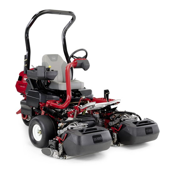
Greensmaster eTriFlex 3360
Toro Greensmaster eTriFlex 3360 Manuals
Manuals and User Guides for Toro Greensmaster eTriFlex 3360. We have
4
Toro Greensmaster eTriFlex 3360 manuals available for free PDF download: Service Manual, Operator's Manual, Installation Instructions Manual
Toro Greensmaster eTriFlex 3360 Service Manual (366 pages)
Brand:
Toro
| Category:
Lawn Mower
| Size: 25 MB
Table of Contents
Table of Contents
7
Preface
8
Chapter 1: Safety
9
Safety Instructions
10
Think Safety First
11
Jacking Instructions
14
Safety and Instructional Decals
15
Chapter 2: Specifications and Maintenance
17
Specifications
18
Overall Dimensions
18
Engine (Model 04580 Only)
18
Chassis
19
DPA Cutting Units
19
Universal Groomer (Optional)
20
Torque Specifications
21
Calculating the Torque Values When Using a Drive-Adapter Wrench
22
Identifying the Fastener
23
Standard Torque for Dry, Zinc Plated, and Steel Fasteners (Inch Series)
24
Standard Torque for Dry, Zinc Plated, and Steel Fasteners (Metric Fasteners)
25
Other Torque Specifications
26
Conversion Factors
26
Shop Supplies
27
Special Tools
29
Chapter 3: Troubleshooting
37
GEARS - the Systematic Approach to Defining, Diagnosing and Solving Problems
38
Operator Advisories
39
Dialogue Messages
41
Machine Faults
43
TRACTION (Example)
75
Using the Infocenter Display for Troubleshooting
75
Troubleshooting
77
General Operation Problems (Model 04580)
78
General Operation Problems (Model 04590)
79
Aftercut Appearance
82
Grooming Performance
84
Universal Groomer Problems (Optional)
85
Battery Charger Error and Fault Codes (Model 04590)
86
Chapter 4: Engine (Model 04580)
87
General Information
88
Traction Unit Operator's Manual
88
Kawasaki Owner's Manual
88
Kawasaki Service Manual
88
Service and Repairs
89
Fuel Tank
89
Evaporative Control System
92
Cooling System
94
Exhaust System
96
Engine
98
Chapter 5: Electrical System
105
General Information
107
Traction Unit Operator's Manual and Accessory Installation Instructions
107
Kawasaki Engine Electrical Components
107
Electrical Drawings
107
Electrical System Operation
108
Traction Subsystem
108
Steering Subsystem
109
Lift/Lower Subsystem
110
Cutting Unit Drive Subsystem
110
12 VDC System Components
110
48V Battery Disconnect
113
Infocenter
114
CAN Bus Communications
116
T1: Primary Controller
118
SC8: Lithium-Ion Battery Controller (Model 04590)
119
T6: Precharge Controller (Model 04590)
121
Electrical System Quick Checks
122
Testing the 12V Charging System (Model 04580)
122
Checking the Interlock System Operation
123
Adjustments
124
Adjusting the Starter/Generator Drive Belt Tension (Model 04580)
124
Adjusting the Steering Position Sensor
125
Adjusting the Manual Parking Brake Switch
126
Testing the Electrical Components
127
Fuses
127
CAN Bus
134
CAN Bus Isolation Module
137
Infocenter Display
137
T1: Primary Controller
138
Starter/Generator (Model 04580)
141
SC8: Lithium-Ion Battery Controller (Model 04590)
144
T6: Precharge Controller (Model 04590)
149
VDC/12 VDC Converter (Model 04590)
153
Front Traction Motor Controllers
155
Front Traction Motor
159
Rear Wheel Traction Motor (Optional 3WD)
161
Steering Input Device
163
Steering Motor
166
Location ID Module
169
Cutting Unit Motors
171
Key Switch (Model 04580)
173
Key Switch (Model 04590)
174
Function Control Switch
175
Light Switch (Optional)
176
Seat Switch
177
Brake Actuator
179
Manual Parking Brake Switch
181
Cutting Unit Lift/Lower Switches
183
Lift/Lower Actuators
185
Engine Oil Pressure Switch (Model 04580)
188
Traction Pedal Position Sensor
190
Steering Position Sensor
193
Relays
196
Contactors
201
Diode Assemblies
203
CAN Bus Terminator Resistors
205
Batteries (Model 04580)
207
Caring for the Batteries (Model 04580)
207
Storing the Batteries (Model 04580)
208
Servicing the Batteries (Model 04580)
209
Batteries (Model 04590)
215
Caring for the Lithium-Ion Batteries (Model 04590)
215
Storing the Lithium-Ion Batteries (Model 04590)
216
Shipping and Transporting the Lithium-Ion Batteries (Model 04590)
216
Charging the Lithium-Ion Batteries (Model 04590)
217
Servicing the Lithium-Ion Batteries (Model 04590)
217
Service and Repairs
224
Generator Assembly (Model 04580)
224
Front Traction Motor
235
Rear Traction Motor (Optional)
237
Cutting Unit Motor
241
Table of Contents
247
Chapter 6 :Chassis
248
General Information
248
Adjustments
249
Adjusting the Brakes
249
Aligning the Rear Wheel Caster Fork
254
Service and Repairs
255
Wheels and Tires
255
Front Wheel Hubs
256
Front Traction Gear Box
257
Front Traction Gear Box Service
259
Rear Wheel Hub (Standard)
261
Rear Wheel Hub (Optional 3WD)
263
Rear Wheel Gear Box (Optional 3WD)
265
Traction Pedal Assembly
268
Brake Assembly
269
Rear Wheel Caster Fork
276
Steering Housing
279
Steering Arm Assembly
281
Control Console
284
Platform Assembly
286
Operator's Seat
287
Frame Assembly
288
Hood Assembly
289
Cutting Unit Suspension Assembly
291
Cutting Unit Suspension Crossarm Assembly
297
Chapter 7: Dpa Cutting Units
299
General Information
300
Cutting Unit Operator's Manual
300
Supporting the Cutting Unit When Servicing
300
Adjustments
301
DPA Cutting Unit Characteristics
301
Leveling the Rear Roller
302
Service and Repairs
304
Bedbar Assembly
304
Bedknife
309
Reel Assembly
312
Electric Cutting Unit Motor Adapter
320
Roller Assemblies
321
Rear Roller Brush (Optional)
328
Chapter 8 :Universalgroomer(Optional)
336
General Information
336
Installation Instructions
336
Service and Repairs
337
The Gear Box Assembly
338
The Idler Assembly
346
The Groomer Reel
348
The Height Adjuster Assembly
351
The Grooming Brush (Optional)
353
Appendix A
355
Electrical Drawing Designations
356
Electrical Schematic - 3360
357
Electrical Schematic - 3370
358
Electrical Schematic - 3370 (Continued
359
Wire Harness Drawing - 3360
360
Wire Harness Diagram - 3360
361
Wire Harness Diagram - 3360 (Continued
362
Wire Harness Drawing - 3370
363
Wire Harness Diagram - 3370
364
Wire Harness Diagram - 3370 (Continued
365
Advertisement
Toro Greensmaster eTriFlex 3360 Service Manual (331 pages)
Brand:
Toro
| Category:
Lawn Mower
| Size: 27 MB
Table of Contents
Table of Contents
7
Chapter 1: Safety
9
Safety Instructions
10
Think Safety First
11
Jacking Instructions
14
Safety and Instructional Decals
15
Chapter 2: Specifications and Maintenance
17
Specifications
18
Overall Dimensions
18
Engine (Model 04580 Only)
18
Chassis
19
DPA Cutting Units
19
Universal Groomer (Optional)
20
Torque Specifications
21
Calculating the Torque Values When Using a Drive-Adapter Wrench
22
Identifying the Fastener
23
Standard Torque for Dry, Zinc Plated, and Steel Fasteners (Inch Series)
24
Standard Torque for Dry, Zinc Plated, and Steel Fasteners (Metric Fasteners)
25
Other Torque Specifications
26
Conversion Factors
26
Shop Supplies
27
Special Tools
29
Chapter 3: Troubleshooting
37
GEARS - the Systematic Approach to Defining, Diagnosing and Solving Problems
38
Operator Advisories
39
Dialogue Messages
41
Machine Faults
43
TRACTION (Example)
72
Using the Infocenter Display for Troubleshooting
72
Troubleshooting
74
General Operation Problems (Information Pending)
75
Aftercut Appearance
76
Grooming Performance
78
Universal Groomer Problems (Optional)
79
Chapter 4: Engine (Model 04580)
81
General Information
82
Traction Unit Operator's Manual
82
Kawasaki Owner's Manual
82
Kawasaki Service Manual
82
Service and Repairs
83
Fuel Tank
83
Evaporative Control System
86
Cooling System
88
Exhaust System
90
Engine
92
Chapter 5: Electrical System
99
General Information
101
Traction Unit Operator's Manual and Accessory Installation Instructions
101
Kawasaki Engine Electrical Components
101
Electrical Drawings
101
48V Battery Disconnect
102
Infocenter
103
CAN Bus Communications
105
T1: Primary Controller
108
T6: Precharge Controller (Model 04590) (Information Pending)
109
Electrical System Operation
110
12 VDC System Operation
110
Electrical System Quick Checks
113
Testing the 12V Charging System (Model 04580)
113
Checking the Interlock System Operation
114
Adjustments
115
Adjusting the Starter/Generator Drive Belt Tension (Model 04580)
115
Adjusting the Steering Position Sensor
116
Adjusting the Manual Parking Brake Switch
118
Testing the Electrical Components
119
Fuses
119
CAN Bus
126
CAN Bus Isolation Module
130
Infocenter Display
131
T1: Primary Controller
131
T6: Precharge Controller (Model 04590) (Information Pending)
134
Starter/Generator (Model 04580)
135
48VDC/12VDC Converter (Model 04590) (Information Pending)
138
Front Traction Motor Controllers
139
Front Traction Motor
141
Rear Wheel Traction Motor (Optional 3WD)
143
Steering Input Device
145
Steering Motor
148
Location ID Module
151
Cutting Unit Motors
153
Key Switch (Model 04580)
155
Key Switch (Model 04590)
156
Function Control Switch
157
Light Switch (Optional)
158
Seat Switch
159
Brake Actuator
161
Manual Parking Brake Switch
163
Cutting Unit Raise and Lower Switches
165
Lift/Lower Actuators
167
Engine Oil Pressure Switch (Model 04580)
170
Traction Pedal Position Sensor
172
Steering Position Sensor
175
Relays
178
Contactors
183
Diode Assemblies
185
CAN Bus Terminator Resistors
187
Generator Assembly (Model 04580)
189
Service and Repairs
189
Front Traction Motor
200
Rear Traction Motor (Optional)
202
Cutting Unit Motor
206
Caring for the Batteries (Model 04580)
212
Storing the Batteries (Model 04580)
213
Servicing the Batteries (Model 04580)
214
Table of Contents
221
Chapter 6 :Chassis
222
General Information
222
Adjustments
223
Adjusting the Brakes
223
Aligning the Rear Wheel Caster Fork
227
Service and Repairs
228
Wheels and Tires
228
Front Wheel Hubs
229
Front Traction Gear Box
230
Front Traction Gear Box Service
232
Rear Wheel Hub (Standard)
234
Rear Wheel Hub (Optional 3WD)
236
Rear Wheel Gear Box (Optional 3WD)
238
Traction Pedal Assembly
241
Brake Assembly
242
Rear Wheel Caster Fork
249
Steering Housing
252
Steering Arm Assembly
254
Control Console
257
Platform Assembly
259
Hood Assembly
260
Cutting Unit Suspension Assembly
262
Cutting Unit Suspension Crossarm Assembly
268
Chapter 7: Dpa Cutting Units
269
General Information
270
Cutting Unit Operator's Manual
270
Supporting the Cutting Unit When Servicing
270
Adjustments
271
DPA Cutting Unit Characteristics
271
Leveling the Rear Roller
272
Service and Repairs
274
Bedbar Assembly
274
Bedknife
279
Reel Assembly
282
Electric Cutting Unit Motor Adapter
290
Roller Assemblies
291
Rear Roller Brush (Optional)
298
Chapter 8 :Universalgroomer(Optional)
306
General Information
306
Installation Instructions
306
Service and Repairs
307
The Gear Box Assembly
308
The Idler Assembly
316
The Groomer Reel
318
The Height Adjuster Assembly
321
The Grooming Brush (Optional)
323
Appendix A
325
Electrical Drawing Designations
326
Electrical Schematic (Model 04580
327
Wire Harness Drawing - Main (Model 04580
328
Wire Harness Diagram - Main (Model 04580
329
Wire Harness Diagram - Main (Model 04580)
330
Toro Greensmaster eTriFlex 3360 Operator's Manual (60 pages)
Traction Unit
Brand:
Toro
| Category:
Lawn Mower
| Size: 6 MB
Table of Contents
Figure 1
2
Table of Contents
3
Safety
4
General Safety
4
Safety and Instructional Decals
4
Setup
7
Installing the Roll Bar
7
Installing the Seat
8
Installing the Service Decal
8
Installing the Steering Wheel
9
Connecting the 12 V Battery
10
Installing the Grass-Basket Hooks
10
Installing the Cutting Units
11
Adjusting the Machine Settings
11
Installing the CE Decals
12
Reducing the Tire Pressure
12
Product Overview
13
Controls
13
Infocenter
15
Specifications
20
Attachments/Accessories
21
Before Operation
22
Before Operation Safety
22
Fuel Specification
22
Filling the Fuel Tank
23
Identifying the Cutting Units
23
Using the Infocenter to Adjust the Machine Settings
24
Understanding the Infocenter Dialog Messages
26
Tilting the Steering Wheel
26
Performing Daily Maintenance
27
During Operation
27
During Operation Safety
27
Breaking in the Machine
28
Starting the Engine
28
Checking the Machine after Starting the Engine
28
Shutting off the Engine
28
Understanding the Safety-Interlock System
29
Driving the Machine Without Mowing
29
Mowing the Green
30
After Operation
31
After Operation Safety
31
Inspecting and Cleaning after Mowing
32
Hauling the Machine
32
Towing the Machine
33
Driving the Machine Without Engine Power
34
Maintenance
35
Maintenance Safety
35
Recommended Maintenance Schedule(S)
35
Daily Maintenance Checklist
36
Pre-Maintenance Procedures
37
Raising the Machine
37
Raising the Hood
38
Engine Maintenance
38
Engine Safety
38
Servicing the Air Cleaner
38
Servicing the Engine Oil
39
Servicing the Spark Plug
41
Fuel System Maintenance
42
Replacing the Fuel Filter
42
Inspecting the Fuel Lines and Connections
43
Electrical System Maintenance
43
Electrical System Safety
43
Disconnecting or Connecting Power to the Machine
43
Charging the 12 V Battery to the 12 V System
43
Understanding the 48 V Battery System
44
Locating the Fuses
45
Drive System Maintenance
47
Checking the Tire Pressure
47
Checking the Torque of the Wheel Nuts
47
Changing the Traction-Motor-Gearbox Fluid
47
Brake Maintenance
49
Adjusting the Brakes
49
Cutting Unit Maintenance
50
Blade Safety
50
Installing and Removing the Cutting Units
50
Checking the Reel-To-Bedknife Contact
52
Backlapping the Cutting Units
53
Storage
54
Storage Safety
54
Preparing the Machine for Storage
54
Advertisement
Toro Greensmaster eTriFlex 3360 Installation Instructions Manual (12 pages)
3WD Kit Traction Unit
Brand:
Toro
| Category:
Tractor Accessories
| Size: 1 MB
Table of Contents
Installing the Gearbox
2
Installing the Fuse
5
Installing the Rear Wheel
5
Completing the Installation
6
Maintenance
7
Advertisement
Related Products
Toro Greensmaster TriFlex 3320/3420
Toro Greensmaster TriFlex 3300
Toro Groundsmaster 3320 30307
Toro Groundsmaster 3320
Toro Greensmaster eTriFlex 3370
Toro 330457
Toro Groundsmaster 3310 Series
Toro Reelmaster 335-D
Toro 3318
Toro 30367
Toro Categories
Lawn Mower
Lawn Mower Accessories
Snow Blower
Lawn and Garden Equipment
Utility Vehicle
More Toro Manuals
Login
Sign In
OR
Sign in with Facebook
Sign in with Google
Upload manual
Upload from disk
Upload from URL