Sign In
Upload
Manuals
Brands
SMC Networks Manuals
Switch
SMCGS10P-Smart
User Manuals: SMC Networks SMCGS10P-Smart Switch
Manuals and User Guides for SMC Networks SMCGS10P-Smart Switch. We have
3
SMC Networks SMCGS10P-Smart Switch manuals available for free PDF download: Management Manual, Installation Manual
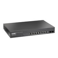
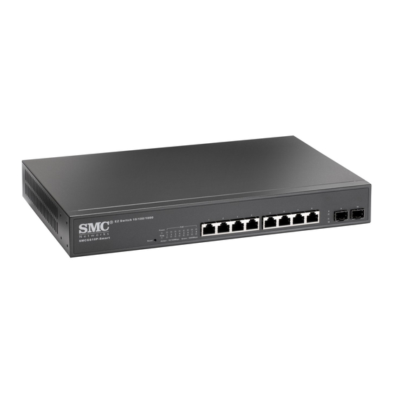
SMC Networks SMCGS10P-Smart Management Manual (288 pages)
Web Smart 10-Port GE PoE Switch
Brand:
SMC Networks
| Category:
Switch
| Size: 3 MB
Table of Contents
Management Guide
1
Warranty and Product Registration
4
About this Guide
5
Table of Contents
7
Contents
7
Figures
13
Tables
17
Sectioni
19
Key Features
20
Table 1: Key Features
20
Description of Software Features
21
System Defaults
25
Table 2: System Defaults
25
Getting Started
19
1 Introduction
19
2 Initial Switch Configuration
28
Ection
30
Web Configuration
30
3 Using the Web Interface
31
Navigating the Web Browser Interface
31
Home Page
31
Figure 1: Home Page
31
Configuration Options
32
Panel Display
32
Figure 2: Front Panel Indicators
32
Table 3: Web Page Configuration Buttons
32
Main Menu
33
Table 4: Main Menu
33
4 Configuring the Switch
41
Configuring System Information
41
Setting an IP Address
42
Setting an Ipv4 Address
42
Figure 3: System Information Configuration
42
Setting an Ipv6 Address
44
Figure 4: IP Configuration
44
Configuring NTP Service
46
Figure 5: Ipv6 Configuration
46
Configuring Remote Log Messages
47
Figure 6: NTP Configuration
47
Configuring Power Reduction
48
Controlling LED Intensity
48
Figure 7: Configuring Settings for Remote Logging of Error Messages
48
Figure 8: Configuring LED Power Reduction
49
Reducing Power to Idle Queue Circuits
50
Configuring Thermal Protection
51
Figure 9: Configuring EEE Power Reduction
51
Configuring Port Connections
52
Figure 10: Configuring Thermal Protection
52
Figure 11: Port Configuration
54
Configuring Security
55
Configuring User Accounts
55
Figure 12: Showing User Accounts
56
Configuring User Privilege Levels
57
Figure 13: Configuring User Accounts
57
Figure 14: Configuring Privilege Levels
58
Configuring the Authentication Method for Management Access
59
Figure 15: Authentication Server Operation
59
Configuring SSH
61
Figure 16: Authentication Method for Management Access
61
Configuring HTTPS
62
Figure 17: SSH Configuration
62
Filtering IP Addresses for Management Access
63
Figure 18: HTTPS Configuration
63
Table 5: HTTPS System Support
63
Figure 19: Access Management Configuration
64
Using Simple Network Management Protocol
65
Table 6: SNMP Security Models and Levels
65
Figure 20: SNMP System Configuration
69
Figure 21: Snmpv3 Community Configuration
70
Figure 22: Snmpv3 User Configuration
72
Figure 23: Snmpv3 Group Configuration
73
Figure 24: Snmpv3 View Configuration
74
Configuring Port Limit Controls
75
Figure 25: Snmpv3 Access Configuration
75
Configuring Authentication through Network Access Servers
77
Figure 26: Port Limit Control Configuration
77
Figure 27: Using Port Security
78
Table 7: Dynamic Qos Profiles
81
Filtering Traffic with Access Control Lists
88
Figure 28: Network Access Server Configuration
88
Figure 29: ACL Port Configuration
90
Figure 30: ACL Rate Limiter Configuration
91
Table 8: QCE Modification Buttons
92
Figure 31: Access Control List Configuration
98
Configuring DHCP Snooping
99
Configuring DHCP Relay and Option 82 Information
101
Figure 32: DHCP Snooping Configuration
101
Configuring IP Source Guard
102
Figure 33: DHCP Relay Configuration
102
Figure 34: Configuring Global and Port-Based Settings for IP Source Guard
104
Configuring ARP Inspection
106
Figure 35: Configuring Static Bindings for IP Source Guard
106
Figure 36: Configuring Global and Port Settings for ARP Inspection
108
Specifying Authentication Servers
109
Figure 37: Configuring Static Bindings for ARP Inspection
109
Figure 38: Authentication Configuration
110
Creating Trunk Groups
111
Configuring Static Trunks
112
Configuring LACP
114
Figure 39: Static Trunk Configuration
114
Configuring the Spanning Tree Algorithm
116
Figure 40: LACP Port Configuration
116
Figure 41: STP Root Ports and Designated Ports
117
Figure 42: MSTP Region, Internal Spanning Tree, Multiple Spanning Tree
117
Configuring Global Settings for STA
118
Figure 43: Common Internal Spanning Tree, Common Spanning Tree, Internal Spanning Tree
118
Configuring Multiple Spanning Trees
122
Figure 44: STA Bridge Configuration
122
Configuring Spanning Tree Bridge Priorities
124
Figure 45: Adding a VLAN to an MST Instance
124
Configuring STP/RSTP/CIST Interfaces
125
Figure 46: Configuring STA Bridge Priorities
125
Table 10: Recommended STA Path Costs
126
Table 11: Default STA Path Costs
126
Table 9: Recommended STA Path Cost Range
126
Figure 47: STP/RSTP/CIST Port Configuration
128
Configuring MIST Interfaces
129
Figure 48: MSTI Port Configuration
130
Multicast VLAN Registration
130
Figure 49: MVR Concept
131
Figure 50: Configuring MVR
133
Configuring Global and Port-Related Settings for IGMP Snooping
134
Figure 51: Configuring Global and Port-Related Settings for IGMP Snooping
136
Configuring VLAN Settings for IGMP Snooping and Query
137
Figure 52: Configuring VLAN Settings for IGMP Snooping and Query
138
Configuring IGMP Filtering
139
Figure 53: IGMP Snooping Port Group Filtering Configuration
139
IGMP Snooping
133
MLD Snooping
140
Configuring Global and Port-Related Settings for MLD Snooping
140
Configuring VLAN Settings for MLD Snooping and Query
143
Figure 54: Configuring Global and Port-Related Settings for MLD Snooping
143
Configuring MLD Filtering
145
Figure 55: Configuring VLAN Settings for MLD Snooping and Query
145
Link Layer Discovery Protocol
146
Configuring LLDP Timing and Tlvs
146
Figure 56: MLD Snooping Port Group Filtering Configuration
146
Configuring LLDP-MED Tlvs
149
Figure 57: LLDP Configuration
149
Power over Ethernet
155
Figure 58: LLDP-MED Configuration
155
Configuring the MAC Address Table
158
Figure 59: Configuring Poe Settings
158
IEEE 802.1Q Vlans
160
Figure 60: MAC Address Table Configuration
160
Assigning Ports to Vlans
161
Configuring VLAN Attributes for Port Members
162
Figure 61: VLAN Membership Configuration
162
Figure 62: VLAN Port Configuration
164
Configuring Private Vlans
165
Using Port Isolation
166
Figure 63: Private VLAN Membership Configuration
166
Figure 64: Port Isolation Configuration
166
Configuring MAC-Based Vlans
167
Protocol Vlans
168
Figure 65: Configuring MAC-Based Vlans
168
Configuring Protocol VLAN Groups
169
Figure 66: Configuring Protocol Vlans
170
Mapping Protocol Groups to Ports
170
Managing Voip Traffic
171
Figure 67: Assigning Ports to Protocol Vlans
171
Configuring Voip Traffic
172
Configuring Telephony OUI
174
Figure 68: Configuring Global and Port Settings for a Voice VLAN
174
Quality of Service
175
Figure 69: Configuring an OUI Telephony List
175
Configuring Port Classification
176
Figure 70: Configuring Ingress Port Qos Classification
177
Configuring Egress Port Scheduler
178
Figure 71: Configuring Ingress Port Tag Classification
178
Figure 72: Displaying Egress Port Schedulers
180
Figure 73: Configuring Egress Port Schedulers and Shapers
180
Configuring Egress Port Shaper
181
Configuring Port Remarking Mode
181
Figure 74: Displaying Egress Port Shapers
181
Figure 75: Displaying Port Tag Remarking Mode
183
Configuring Port DSCP Translation and Rewriting
184
Figure 76: Configuring Port Tag Remarking Mode
184
Configuring DSCP-Based Qos Ingress Classification
186
Figure 77: Configuring Port DSCP Translation and Rewriting
186
Configuring DSCP Translation
187
Figure 78: Configuring DSCP-Based Qos Ingress Classification
187
Configuring DSCP Classification
188
Figure 79: Configuring DSCP Translation and Re-Mapping
188
Configuring Qos Control Lists
189
Figure 80: Mapping DSCP to Cos/Dpl Values
189
Table 12: QCE Modification Buttons
190
Configuring Storm Control
193
Figure 81: Qos Control List Configuration
193
Configuring Port Mirroring
194
Figure 82: Storm Control Configuration
194
Figure 83: Mirror Configuration
195
Configuring Upnp
196
Figure 84: Upnp Configuration
197
5 Monitoring the Switch
199
Displaying Basic Information about the System
199
Displaying System Information
199
Displaying CPU Utilization
200
Figure 85: System Information
200
Displaying Log Messages
201
Figure 86: CPU Load
201
Figure 87: System Log Information
202
Displaying Log Details
203
Displaying Thermal Protection
203
Figure 88: Detailed System Log Information
203
Displaying Information about Ports
204
Displaying Port Status on the Front Panel
204
Figure 89: Thermal Protection Status
204
Figure 90: Port State Overview
204
Displaying an Overview of Port Statistics
205
Displaying Qos Statistics
205
Figure 91: Port Statistics Overview
205
Displaying QCL Status
206
Figure 92: Queueing Counters
206
Displaying Detailed Port Statistics
207
Figure 93: Qos Control List Status
207
Figure 94: Detailed Port Statistics
209
Displaying Information about Security Settings
210
Displaying Access Management Statistics
210
Figure 95: Access Management Statistics
210
Displaying Information about Switch Settings for Port Security
211
Figure 96: Port Security Switch Status
212
Displaying Information about Learned MAC Addresses
213
Figure 97: Port Security Port Status
213
Displaying Port Status for Authentication Services
214
Service
215
Figure 98: Network Access Server Switch Status
215
Displaying ACL Status
219
Figure 99: NAS Statistics for Specified Port
219
Figure 100: ACL Status
220
Displaying Statistics for DHCP Snooping
221
Displaying DHCP Relay Statistics
222
Figure 101: DHCP Snooping Statistics
222
Displaying MAC Address Bindings for ARP Packets
223
Figure 102: DHCP Relay Statistics
223
Displaying Entries in the IP Source Guard Table
224
Figure 103: Dynamic ARP Inspection Table
224
Figure 104: Dynamic IP Source Guard Table
224
Displaying Information on Authentication Servers
225
Displaying a List of Authentication Servers
225
Figure 105: RADIUS Overview
225
Displaying Statistics for Configured Authentication Servers
226
Displaying Information on LACP
229
Displaying an Overview of LACP Groups
229
Figure 106: RADIUS Details
229
Displaying LACP Port Status
230
Figure 107: LACP System Status
230
Displaying LACP Port Statistics
231
Figure 108: LACP Port Status
231
Figure 109: LACP Port Statistics
231
Displaying Information on the Spanning Tree
232
Displaying Bridge Status for STA
232
Displaying Port Status for STA
234
Figure 110: Spanning Tree Bridge Status
234
Figure 111: Spanning Tree Detailed Bridge Status
234
Displaying Port Statistics for STA
235
Figure 112: Spanning Tree Port Status
235
Displaying MVR Information
236
Displaying MVR Statistics
236
Figure 113: Spanning Tree Port Statistics
236
Displaying MVR Group Information
237
Figure 114: MVR Statistics
237
Showing IGMP Snooping Information
238
Showing IGMP Snooping Status
238
Figure 115: MVR Group Information
238
Figure 116: IGMP Snooping Status
239
Showing IGMP Snooping Group Information
239
Figure 117: IGMP Snooping Group Information
240
Showing Ipv4 SSM Information
240
Showing MLD Snooping Information
241
Showing MLD Snooping Status
241
Figure 118: Ipv4 SSM Information
241
Showing MLD Snooping Group Information
242
Figure 119: MLD Snooping Status
242
Showing Ipv6 SSM Information
243
Figure 120: MLD Snooping Group Information
243
Figure 121: Ipv6 SSM Information
243
Displaying LLDP Information
244
Displaying LLDP Neighbor Information
244
Table 13: System Capabilities
244
Displaying LLDP-MED Neighbor Information
245
Figure 122: LLDP Neighbor Information
245
Displaying LLDP Neighbor EEE Information
247
Figure 123: LLDP-MED Neighbor Information
247
Figure 124: LLDP Neighbor EEE Information
248
Displaying LLDP Port Statistics
249
Displaying LLDP Neighbor Poe Information
250
Figure 125: LLDP Port Statistics
250
Displaying Poe Status
251
Figure 126: LLDP Neighbor Poe Information
251
Displaying the MAC Address Table
252
Figure 127: Power over Ethernet Status
252
Displaying Information about Vlans
253
VLAN Membership
253
Figure 128: MAC Address Table
253
VLAN Port Status
254
Figure 129: Showing VLAN Members
254
Figure 130: Showing VLAN Port Status
255
Displaying Information about MAC-Based Vlans
256
Figure 131: Showing MAC-Based VLAN Configuration
256
6 Performing Basic Diagnostics
257
Pinging an Ipv4 or Ipv6 Address
257
Running Cable Diagnostics
258
Figure 132: ICMP Ping
258
Figure 133: Veriphy Cable Diagnostics
259
7 Performing System Maintenance
261
Restarting the Switch
261
Figure 134: Restart Device
261
Restoring Factory Defaults
262
Upgrading Firmware
262
Figure 135: Factory Defaults
262
Managing Configuration Files
263
Saving Configuration Settings
263
Figure 136: Software Upload
263
Restoring Configuration Settings
264
Figure 137: Configuration Save
264
Figure 138: Configuration Upload
264
Ection
265
Appendices
265
Specifications
266
Software Features
266
Management Features
267
Standards
268
Management Information Bases
268
B Troubleshooting
270
Problems Accessing the Management Interface
270
Table 14: Troubleshooting Chart
270
Using System Logs
271
Information
272
The GNU General Public License
272
License Information
273
Glossary
276
Index
284
Advertisement
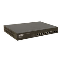
SMC Networks SMCGS10P-Smart Installation Manual (68 pages)
Web Smart 10-Port Gigabit Ethernet PoE Switch
Brand:
SMC Networks
| Category:
Network Router
| Size: 2 MB
Table of Contents
Installation Guide
1
Warranty and Product Registration
4
Compliances and Safety Statements
5
About this Guide
15
Table of Contents
17
Contents
20
Tables
21
Figures
23
Introduction
25
Overview
25
Figure 1: Front Panel
25
Figure 2: Rear Panel
26
Network Management Options
26
Power-Over-Ethernet
26
Switch Architecture
26
Description of Hardware
27
10/100/1000BASE-T Ports
27
SFP Transciever Slots
27
Port and System Leds
28
Table 1: Supported SFP Transceivers
28
Table 2: Port Status Leds
29
Table 3: System Status Leds
29
Figure 3: Port and System Leds
29
Power Supply Inlet
30
Grounding Point
30
Figure 4: Power Supply Inlet
30
Reset Button
31
Figure 5: Grounding Point
31
Figure 6: Reset Button
31
Network Planning
33
Introduction to Switching
33
Application Examples
34
Collapsed Backbone
34
Figure 7: Collapsed Backbone
34
Poe Connections
35
Figure 8: Supplying Poe Power
35
Network Aggregation Plan
36
Figure 9: Network Aggregation Plan
36
Figure 10: Remote Connections with Fiber Cable
37
Figure 11: Making VLAN Connections
38
Application Notes
39
Installing the Switch
41
Selecting a Site
41
Ethernet Cabling
42
Equipment Checklist
43
Mounting
44
Rack-Mounting
44
Figure 13: Grounding
44
Figure 14: Attaching the Brackets
45
Figure 15: Installing the Switch in a Rack
45
Desktop or Shelf Mounting
47
Connecting to a Power Source
48
Installing an Optional SFP Transceiver
49
Making Network Connections
52
Twisted-Pair Devices
52
Cabling Guidelines
52
Connecting to Pcs, Servers, Hubs and Switches
52
Figure 19: Making Twisted-Pair Connections
52
Network Wiring Connections
53
Figure 20: Network Wiring Connections
54
Fiber Optic SFP Devices
55
Figure 21: Making Fiber Port Connections
56
Connectivity Rules
57
1000BASE-T Cable Requirements
57
1000 Mbps Gigabit Ethernet Collision Domain
57
Table 4: Maximum 1000BASE-T Gigabit Ethernet Cable Length
57
Table 5: Maximum 1000BASE-SX Gigabit Ethernet Cable Lengths
57
100 Mbps Fast Ethernet Collision Domain
58
Mbps Ethernet Collision Domain
58
Table 6: Maximum 1000BASE-LX Gigabit Ethernet Cable Length
58
Table 7: Maximum 1000BASE-LH Gigabit Ethernet Cable Length
58
Table 8: Maximum 100BASE-FX Cable Length
58
Table 9: Maximum Fast Ethernet Cable Lengths
58
Table 10: Maximum Ethernet Cable Length
58
Cable Labeling and Connection Records
59
Table 11: LED Indicators
61
Troubleshooting
62
Installation
62
In-Band Access
62
Specifications
63
Physical Characteristics
63
Switch Features
65
Management Features
65
Standards
65
Compliances
66
SMC Networks SMCGS10P-Smart Installation Manual (59 pages)
EZ Switch 10/100/1000 Web Smart 10-Port Gigabit Ethernet PoE Switch
Brand:
SMC Networks
| Category:
Network Router
| Size: 2 MB
Table of Contents
Installation Guide
1
Warranty and Product Registration
4
Compliances and Safety Statements
5
About this Guide
15
Table of Contents
17
Contents
17
Tables
19
Figures
21
Introduction
22
Overview
22
Figure 1: Front Panel
22
Figure 2: Rear Panel
23
Network Management Options
23
Power-Over-Ethernet
23
Switch Architecture
23
Description of Hardware
24
Figure 3: Port and System Leds
25
Table 1: Supported SFP Transceivers
25
Table 2: Port Status Leds
26
Table 3: System Status Leds
26
Figure 4: Power Supply Inlet
27
Figure 5: Grounding Point
28
Figure 6: Reset Button
28
Network Planning
30
Introduction to Switching
30
Application Examples
30
Collapsed Backbone
30
Poe Connections
31
Figure 7: Collapsed Backbone
31
Network Aggregation Plan
32
Figure 8: Supplying Poe Power
32
Figure 9: Network Aggregation Plan
32
Figure 10: Remote Connections with Fiber Cable
33
Application Notes
34
Figure 11: Making VLAN Connections
34
Installing the Switch
36
Selecting a Site
36
Ethernet Cabling
37
Equipment Checklist
38
Optional Rack-Mounting Equipment
38
Mounting
39
Rack-Mounting
39
Figure 13: Grounding
39
Figure 14: Attaching the Brackets
40
Figure 15: Installing the Switch in a Rack
40
Figure 16: Attaching the Adhesive Feet
41
Connecting to a Power Source
42
Figure 17: Power Inlet
42
Installing an Optional SFP Transceiver
43
Figure 18: Installing an Optional SFP Transceiver into a Slot
43
Making Network Connections
44
Connecting Network Devices
44
Twisted-Pair Devices
44
Power-Over-Ethernet Connections
44
Cabling Guidelines
45
Connecting to Pcs, Servers, Hubs and Switches
45
Figure 19: Making Twisted-Pair Connections
45
Network Wiring Connections
46
Fiber Optic SFP Devices
47
Figure 20: Network Wiring Connections
47
Figure 21: Making Fiber Port Connections
48
Connectivity Rules
49
1000BASE-T Cable Requirements
49
1000 Mbps Gigabit Ethernet Collision Domain
49
Table 4: Maximum 1000BASE-T Gigabit Ethernet Cable Length
49
Table 5: Maximum 1000BASE-SX Gigabit Ethernet Cable Lengths
49
100 Mbps Fast Ethernet Collision Domain
50
Table 6: Maximum 1000BASE-LX Gigabit Ethernet Cable Length
50
Table 7: Maximum 1000BASE-LH Gigabit Ethernet Cable Length
50
Table 8: Maximum 100BASE-FX Cable Length
50
Table 9: Maximum Fast Ethernet Cable Lengths
50
Mbps Ethernet Collision Domain
51
Cable Labeling and Connection Records
51
Table 10: Maximum Ethernet Cable Length
51
A T Roubleshooting
52
Diagnosing LED Indicators
52
Power and Cooling Problems
52
Table 11: LED Indicators
52
Troubleshooting
53
Installation
53
In-Band Access
53
Specifications
54
Physical Characteristics
54
Switch Features
56
Management Features
56
Standards
56
Compliances
57
Advertisement
Advertisement
Related Products
SMC Networks EZ Switch SMCGS16
SMC Networks EZ Switch SMCGS16-Smart
SMC Networks SMCGS10C-Smart
SMC Networks EZ Switch SMCGS24
SMC Networks SMC EZ Switch 10/100/1000 SMCGS8P-Smart
SMC Networks SMCGS501 - FICHE TECHNIQUE
SMC Networks SMCGS801 - FICHE TECHNIQUE
SMC Networks EZ Switch SMCGS24-Smart
SMC Networks EZSwitch SMCGS24C-Smart
SMC Networks SMCGS805
SMC Networks Categories
Switch
Control Unit
Controller
Industrial Equipment
Network Router
More SMC Networks Manuals
Login
Sign In
OR
Sign in with Facebook
Sign in with Google
Upload manual
Upload from disk
Upload from URL