Sign In
Upload
Manuals
Brands
Siemens Manuals
Inverter
SINAMICS G180
Siemens SINAMICS G180 Manuals
Manuals and User Guides for Siemens SINAMICS G180. We have
3
Siemens SINAMICS G180 manuals available for free PDF download: Installation And Operating Instructions Manual, Manual
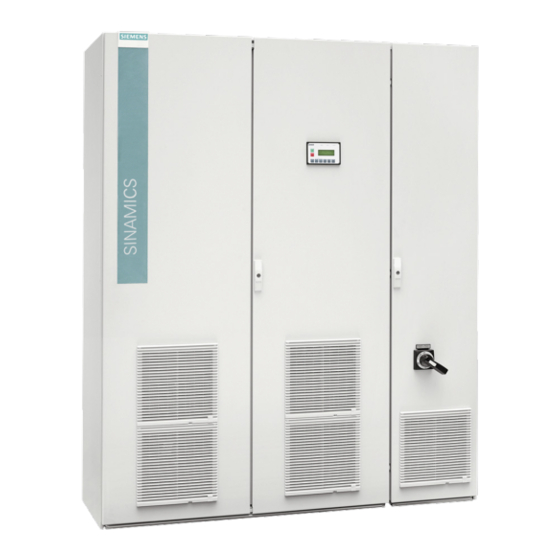
Siemens SINAMICS G180 Installation And Operating Instructions Manual (218 pages)
Inverters - compact units, cabinet systems, Cabinet units air and liquid cooled
Brand:
Siemens
| Category:
Inverter
| Size: 6.78 MB
Table of Contents
Table of Contents
5
1 Introduction
11
About These Instructions
11
Validity
11
Text Format Features
11
Presentation of the Display Buttons in the Operating Instructions
12
Specific Features
12
2 Safety Information
15
The Five Safety Rules
15
Use of Tested, Certified and Siemens-Approved Components
16
Areas that Are Potentially and Particularly Hazardous
17
Notes for Operator Protection
18
Notes on Liquid Cooling
21
Safety Precautions When Handling Anti-Freeze
22
Standards and Guidelines for Proper Use of Inverters
23
Plant Safety
24
Security Information
25
Components that Can be Destroyed by Electrostatic Discharge (ESD)
26
Electromagnetic Fields
28
Radio Telephones and Mobile Telephones
29
Note Regarding Fiber-Optic Cables
30
Protecting/Fusing the External 230 V AC Control Voltage
30
Residual Risks
31
3 Description
33
Updating Inverter Software or Instructions
33
Order Numbers / Type Designations
33
Accessories
39
Use of Tested, Certified and Siemens-Approved Components
39
Peripheral Boards 1 to 4, -A95, Option G02 to G05
39
General Information about the Peripheral Boards 1 to 4
39
Electronic Shutdown for "Safe Halt" / PTC Inputs
41
Safe Torque Off" with Single Circuit Trip
44
Safe Torque Off" with Two Circuit Version
45
Switchover, Single Circuit <-> Two Circuit Tripping
45
Checking the "Safe Halt" Function
47
PTC Inputs for Motor PTC Thermistor
49
Brake Transistor and Brake Resistor
51
Dimensioning the Brake Resistor
51
Connecting the Brake Resistor
51
Parameter Overview
52
Factory Settings" Application
52
Protective Cover IP21 for Compact and Compact Plus Devices
53
Main Switch "Q 2T
54
DC Link Terminals for Compact Devices
54
External Display
56
RFI Suppression Filter, Category C1 (Class B)
57
Strengthened Du/Dt Filter
57
Sine-Wave Filter
57
Additional Mains Power Protection Chokes
57
Optional Fieldbus Connection
58
Profibus Dp
58
Profinet Io
59
Modbus RTU
62
Modbus TCP
65
Pre-Switch Mode Power Supply 300 W
67
Water Cooling
68
General Information about Water Cooling
68
Direct Water Cooling Diagram
69
Connecting Water Cooling
70
Venting the Water Cooling
70
Decommissioning and Shutdown
71
Cooling Water Additives for the Closed Inverter Cooling with Cooling Unit (Optional)
71
4 Preparations for Use
73
Transporting Inverter
73
Storage of the Inverters
76
Emc
77
Install and Connect in Accordance with EMC
77
Examples for Correct EMC Connection
78
Radio Interference Class
80
EMC Environment Category
81
Realizing Operation in the Explosion-Protected Zone
82
5 Installation
85
Installing Inverter - General Notes
85
Installing Compact Devices
86
Protective Cover IP21 for Compact and Compact Plus Devices
87
Installing Cabinet Units
88
Mounting an External Display (Option)
90
6 Electrical Connection
93
General Information about the Electrical Connection
93
Protecting the Inverter
94
Circuit Breaker
94
Connecting Control Cable
95
Line Supply Connection
95
Suitable Supply Line Configurations
95
Dimensioning Mains Power Cables
96
RCD Circuit Breaker
96
Connecting Mains Power Cable to the Inverter
97
Inverter Connection for Different Pulse Operation
98
Adjusting the Line Voltage at the Inverter
99
Motor Connection
100
Motor Selection
100
Coil Load
101
Motor Voltage and Type of Circuit
101
Dimensioning Motor Cables
102
Dimensioning Maximum Motor Cable Length
102
Connecting Motor Cable
104
Connecting the PTC Thermistor of the Motor to the Inverter
104
External Control Voltage
105
Use of External Control Voltage
105
Connecting the External 230 V AC Control Voltage
105
Protecting/Fusing the External 230 V AC Control Voltage
105
Switching over the Hardware to an External 230 V AC Control Voltage
106
Preparations for Accessing the "Switching Power Supply" Board
106
Connecting the External 230 V AC for Compact Devices
113
Control Voltage 230 V AC for Cabinet Units
113
Connecting the External 24 V DC Control Voltage
114
Protecting/Fusing the External 24 V DC Control Voltage
114
Switching over the Hardware to an External 24 V DC Control Voltage
114
7 Commissioning
117
Checks Without Mains Power Supply and Without Motor
117
Checks with Mains Power Supply and Without Motor
119
Checks with Mains Power Supply and with Motor
123
Checking with Motor Coupled to the Work Machine
124
8 Operation
125
Function of the Inverter Display
125
Switching the Unit on and off
127
Setting the Language
127
Setting the Date and Time
128
Setting the Level of Detail of the Inverter Menu
128
Inverter Operating Commands
128
Configuring Operating Sources
130
Invoking Mode Configurations
130
Communication Options
131
Meaning of the Abbreviations for Operating Functions
132
P-Fieldbus" Function
132
Function of "P-DIGITAL OUTPUTS
133
Function of "P-ANALOG OUTPUTS
133
Operation of Several Inverters on One PC
133
Communication Via PROFINET IO
134
Communication Services and Port Numbers Used for PROFINET IO
134
Overview
135
Network Security
136
Separation between Production and Office Networks
136
Network Segmentation with SCALANCE S
137
Standard Mode Settings
137
Mode "Std Siss
137
Mode "Std Sisd
138
Mode "Std Dids
139
Mode "Std DIDD
140
NAMUR Mode Settings
140
Operation According to NAMUR Defaults
140
Operation According to "NAMUR 1
141
Operation According to "NAMUR 2
142
Operation According to "NAMUR 3
143
Operation According to "NAMUR 4
144
Operation According to "NAMUR 5
145
Operation According to "NAMUR 6
146
Controlling the External Connections of the Inverter
147
Function of the Control Cable Terminals
147
Protective Separation According to en 61800-5-1
147
Sub-D and USB Connections and DIL Switches
150
USB Interface
151
DIL Switches "S1" and "S2
151
Connecting Encoders
153
Connect the PC Via USB at -X50B
155
Connecting a PC to -X51 Via RS 232
156
Connection for Optional External Display with RS 485
157
Special Functions
158
Protective Functions
158
Multiple Function of the Analog and Digital Inputs
162
Setpoint Channel and Closed-Loop Control
166
Specifying Source for Speed Setpoint
166
Parameterization
166
Principle of Operation of the Configuration
166
Protecting Parameters against Modification
168
Configuration Using the Inverter Display
168
More Documentation about Parameterization
169
Examples / Applications
170
Standard" Application
170
Standard Control Cable Terminals
170
Control Cable Terminals "Peripheral Board 1
171
Control Cable Terminals "Peripheral Board 2
171
Control Cable Terminals "Peripheral Board 3
172
Control Cable Terminals "Peripheral Board 4
173
Mode Setting of the "Standard" Application
173
Assignment of the Digital Inputs
174
Assignment of the Digital Outputs
174
Assignment of the Analog Inputs
174
Assignment of the Analog Outputs
175
Input "Safe Torque Off" / PTC Thermistor Inputs on Peripheral Board
175
NAMUR" Application
177
Control Cable Terminals for "NAMUR" Application
177
Control Cable Terminals "Peripheral Board 4
179
Mode Setting of the NAMUR Application
180
Assignment of the Relay Outputs
180
Assignment of the Analog Inputs
181
Assignment of the Analog Outputs
181
Input "Mandatory Mains Power Isolation" / PTC Thermistor Inputs on Peripheral Board
181
9 Maintenance
183
Maintenance and Servicing
183
Replacing Compact Device
184
Replacing Fans for the Compact Device
185
Maintenance and Service of Water Cooling (Option)
185
Decommissioning
185
10 Spare Parts
187
Non-Approved Spare Parts
187
11 Diagnostics, Faults and Warnings
189
Reading Event Log
190
Service & Support
191
Contacts in Ruhstorf an der Rott Location (Germany)
192
Quality Documents
193
Technical Data
195
Technical Data for Transportation
196
Technical Data for Storage
196
C.1 Technical Data for Transportation
196
Frame Sizes of Compact Units
197
Frame Sizes of Cabinet Units
199
Technical Data for Operation
202
Tightening Torques for Power Cables
203
Technical Data of the Control Cable Terminals
203
Technical Data and Identification of the PTC Thermistor Input at Peripheral Boards 2 and 4
205
Technical Data of the Direct Water Cooling
206
Permissible Substance Values for the Cooling Water
207
Threshold Values for Fan Control System
208
Derating
208
Current Derating
208
Voltage Derating
211
C.12.2 Voltage Derating
211
List of Abbreviations
213
Index
215
Advertisement
Siemens SINAMICS G180 Installation And Operating Instructions Manual (190 pages)
Compact inverter units, cabinet systems, air-cooled and liquid-cooled cabinet units
Brand:
Siemens
| Category:
Inverter
| Size: 4.9 MB
Table of Contents
Table of Contents
5
About These Instructions
11
Introduction
11
Text Format Features
11
Warnings
11
Presentation of the Display Buttons in the Operating Instructions
12
Specific Features
12
Safety Information
15
The Five Safety Rules
15
Areas that Are Potentially and Particularly Hazardous
16
Use of Tested, Certified and Siemens-Approved Components
16
Notes for Operator Protection
18
Notes on Water Cooling
21
Safety Precautions When Handling Anti-Freeze
22
Standards and Guidelines for Proper Use of Inverters
23
Plant Safety
24
Components that Can be Destroyed by Electrostatic Discharge (ESD)
25
Electromagnetic Fields
26
Radio Telephones and Mobile Telephones
27
Note Regarding Fiber-Optic Cables
28
Provide Fuse Protection for External Control Voltage
28
Description
29
Order Numbers / Type Designations
29
Updating Inverter Software or Instructions
29
Preparations for Use
35
Transporting Inverter
35
Storage of the Inverters
38
Emc
39
Install and Connect in Accordance with EMC
39
Examples for Correct EMC Connection
40
Radio Interference Class
42
EMC Environment Category
43
Realizing Operation in the Explosion-Protected Zone
44
Installation
47
Installing Inverter - General Notes
47
Installing Compact Devices
48
Protective Cover IP21 for Compact and Compact Plus Devices
48
Installing Cabinet Units
49
Installing External Display
50
Electrical Connection
53
General Information about the Electrical Connection
53
Protecting the Inverter
53
Circuit Breaker
54
Connecting Control Cable
54
Dimensioning Mains Power Cables
55
Line Supply Connection
55
Suitable Supply Line Configurations
55
Connecting Mains Power Cable to the Inverter
56
Inverter Connection for Different Pulse Operation
57
Adjusting the Line Voltage at the Inverter
58
Motor Connection
59
Motor Selection
59
Coil Load
60
Dimensioning Motor Cables
60
Motor Voltage and Type of Circuit
60
Dimensioning Maximum Motor Cable Length
61
Connecting Motor Cable
62
Connecting the PTC Thermistor of the Motor to the Inverter
63
Connection of External Control Voltage
63
Provide Fuse Protection for External Control Voltage
63
Use of External Control Voltage
63
Adapting the Hardware to External Control Voltage
64
Preparations for Accessing the "Switching Power Supply" Board
64
Preparing Compact Devices with Size up to 165 MM
64
Preparing Compact Devices with Frame Size K4 with 400 V or 500 V
65
Preparing Compact Devices with Size up to 225 MM
65
Providing Compact Devices with the Frame Size K4 with 690 V
66
Providing Compact Devices with Frame Size K5/51 with 400 V or 500 V
67
Providing Compact Devices with the Frame Size K5/51 with 690 V
68
Preparing Compact Devices with Frame Size K6 with 400 V or 500 V
69
Providing Compact Devices with the Frame Size K6 with 690 V
69
Connecting External Control Voltage for Compact Devices
70
Control Voltage 230 V for Cabinet Units
71
Checks Without Mains Power Supply and Without Motor
73
Commissioning
73
Checks with Mains Power Supply and Without Motor
75
Checks with Mains Power Supply and with Motor
79
Checking with Motor Coupled to the Work Machine
80
Function of the Inverter Display
81
Operation
81
Switching the Unit on and off
82
Inverter Operating Commands
83
Setting the Date and Time
83
Setting the Language
83
Setting the Level of Detail of the Inverter Menu
83
Configuring Operating Sources
85
Invoking Mode Configurations
85
Communication Options
86
Function of "P-DIGITAL OUTPUTS
87
Function of "P-Profibus/Modbus
87
Meaning of the Abbreviations for Operating Functions
87
Function of "P-ANALOG OUTPUTS
88
Operation of Several Inverters on One PC
88
Mode "Std Siss
89
Standard Mode Settings
89
Mode "Std Sisd
90
Mode "Std Dids
91
Mode "Std DIDD
92
NAMUR Mode Settings
92
Operation According to NAMUR Defaults
92
Operation According to "NAMUR 1
93
Operation According to "NAMUR 2
94
Operation According to "NAMUR 3
95
Operation According to "NAMUR 4
96
Operation According to "NAMUR 5
97
Operation According to "NAMUR 6
98
Controlling the External Connections of the Inverter
99
Function of the Control Cable Terminals
99
Protective Separation According to en 61800-5-1
99
Sub-D and USB Connections and DIL Switches
102
USB Interface
102
DIL Switches "S1" and "S2
103
Connecting Encoders
105
Connect the PC Via USB at -X50B
107
Connecting a PC to -X51 Via RS 232
108
Connection for Optional External Display with RS 485
109
Protective Functions
110
Special Functions
110
Multiple Function of the Analog and Digital Inputs
114
Parameterization
118
Principle of Operation of the Configuration
118
Setpoint Channel and Closed-Loop Control
118
Specifying Source for Speed Setpoint
118
Configuration Using the Inverter Display
120
More Documentation about Parameterization
120
Protecting Parameters against Modification
120
Examples / Applications
121
Standard Control Cable Terminals
121
Standard" Application
121
Control Cable Terminals "Peripheral Board 1
122
Control Cable Terminals "Peripheral Board 2
122
Control Cable Terminals "Peripheral Board 3
123
Control Cable Terminals "Peripheral Board 4
124
Mode Setting of the "Standard" Application
124
Assignment of the Analog Inputs
125
Assignment of the Digital Inputs
125
Assignment of the Digital Outputs
125
Assignment of the Analog Outputs
126
Input "Safe Halt" / PTC Thermistor Inputs on Peripheral Board
126
Control Cable Terminals for "NAMUR" Application
127
NAMUR" Application
127
Control Cable Terminals "Peripheral Board 4
128
Mode Setting of the NAMUR Application
129
Assignment of the Analog Inputs
130
Assignment of the Relay Outputs
130
Assignment of the Analog Outputs
131
Input "Mandatory Mains Power Isolation" / PTC Thermistor Inputs on Peripheral Board
131
Maintenance
133
Maintenance and Servicing
133
Replacing Compact Device
134
Decommissioning
135
Maintenance and Service of Water Cooling (Option)
135
Replacing Fans for the Compact Device
135
Spare Parts and Accessories
137
Use of Tested, Certified and Siemens-Approved Components
137
General Information about the Peripheral Boards 1 to 4
138
Peripheral Boards 1 to 4
138
Electronic Shutdown for "Safe Halt" / PTC Inputs
139
General Information about Electronic Shutdown
139
Motor Temperature Monitoring Shutdown Concept
139
Standards for Electronic Shutdown
139
Risk Comparison
140
Safe Halt
141
Checking the "Safe Halt" Function
142
Safe Halt" in the DC Link Version
142
Checking the PTC Thermistor Shutdown Function
143
PTC Inputs for Motor PTC Thermistor
143
Brake Transistor and Brake Resistor
144
Connecting the Brake Resistor
145
Dimensioning the Brake Resistor
145
Factory Settings" Application
145
Parameter Overview
145
Main Switch "Q 2T
146
Protective Cover IP21 for Compact and Compact Plus Devices
146
DC Link Terminals for Compact Devices
147
External Display
149
RFI Suppression Filter, Category C1 (Class B)
149
Additional Mains Power Protection Chokes
150
Profibus DP
150
Sine-Wave Filter
150
Strengthened Du/Dt Filter
150
Modbus RTU
152
Modbus TCP
154
General Information about Water Cooling
156
Water Cooling
156
Direct Water Cooling Diagram
157
Connecting Water Cooling
158
Venting the Water Cooling
158
Cooling Water Additives for the Closed Inverter Cooling with Cooling Unit (Optional)
159
Decommissioning and Shutdown
159
Diagnostics, Faults and Warnings
161
Reading Event Log
161
Service & Support
163
Siemens Industry Online Support
163
Contacts in Ruhstorf an der Rott Location (Germany)
164
Quality Documents
165
Technical Data
171
Technical Data for Transportation
171
Technical Data for Storage
172
Frame Sizes of Compact Units
173
Frame Sizes of Cabinet Units
175
Technical Data for Operation
177
Technical Data of the Control Cable Terminals
178
Tightening Torques for Power Cables
178
Technical Data and Identification of the PTC Thermistor Input at Peripheral Boards 2 and 4
179
Technical Data of the Direct Water Cooling
180
Permissible Substance Values for the Cooling Water
182
Threshold Values for Fan Control System
182
C.12 Derating
183
Current Derating
183
Derating
183
C.12.2 Voltage Derating
185
Voltage Derating
185
List of Abbreviations
187
Index
189
Siemens SINAMICS G180 Manual (62 pages)
Brand:
Siemens
| Category:
Monitor
| Size: 0.75 MB
Table of Contents
Table of Contents
5
1 Introduction
7
2 Safety Instructions
9
Security Information
9
3 List of Messages
11
4 Assignment of the Message Groups for the Bit Generators
45
Service & Support
57
List of Abbreviations
59
Index
61
Advertisement
Advertisement
Related Products
Siemens SINAMICS G120C
Siemens SINAMICS G110M
Siemens SINAMICS V20 Inverter
Siemens SINAMICS V10
Siemens SINAMICS Series
Siemens Sinamics ET 200pro FC-2
Siemens SINAMICS G110D
Siemens SINAMICS G120 CU250S-2 Series
Siemens SINAMICS G120 CU240E-2
Siemens SINAMICS G120 PM240P-2
Siemens Categories
Industrial Equipment
Controller
Control Unit
Oven
Washer
More Siemens Manuals
Login
Sign In
OR
Sign in with Facebook
Sign in with Google
Upload manual
Upload from disk
Upload from URL