Sign In
Upload
Manuals
Brands
Siemens Manuals
Inverter
Sinamics ET 200pro FC-2
Siemens Sinamics ET 200pro FC-2 Manuals
Manuals and User Guides for Siemens Sinamics ET 200pro FC-2. We have
2
Siemens Sinamics ET 200pro FC-2 manuals available for free PDF download: Function Manual, Operating Instructions Manual
Siemens Sinamics ET 200pro FC-2 Function Manual (450 pages)
Safety Integrated
Brand:
Siemens
| Category:
Inverter
| Size: 9.04 MB
Table of Contents
Description
3
Change History
5
Table of Contents
7
1 Fundamental Safety Instructions
13
General Safety Instructions
13
Industrial Security
14
2 Introduction
15
About this Manual
15
Navigator through the "Safety Integrated" Function Manual
18
3 Description
21
About this Chapter
21
Basic Functions and Extended Functions
22
Interfaces to Select the Safety Functions
24
Preconditions When Using the Safety Functions
26
Restrictions When Using Safety Functions
27
Recommendations for Stable Operation
30
An Overview of the Principle of Operation of the Safety Functions
31
Safe Torque off (STO)
31
Safe Brake Control (SBC)
34
Safe Stop 1 (SS1)
36
Safely Limited Speed (SLS)
39
Safe Direction (SDI)
42
Safe Speed Monitoring (SSM)
44
4 Installing
45
About this Chapter
45
Sequence When Installing an Inverter with Safety Functions
46
Connection Via Profisafe
47
Overview of Profisafe Connections
47
Profisafe Telegrams
51
Control Word 1 and Status Word 1 (Basic Functions)
52
Control Word 1 and Status Word 1 (Extended Functions)
53
Control Word 5 and Status Word 5
54
Application Examples
56
Controlling Via a Fail-Safe Digital Input
58
Overview
58
Wiring Examples According to SIL 2 and PL D
62
Electromechanical Sensor
63
Series-Connected Electromechanical Sensors
66
Controlling Several Inverters in Parallel Using Electromechanical Sensors
68
SIRIUS 3SK1 Safety Relay
70
3RK3 Modular Safety System
72
Sensors with OSSD Outputs
74
SIMATIC I/O Modules
76
Wiring Examples According to SIL 3 and PL E
83
Electromechanical Sensor
84
SIRIUS 3SK1 Safety Relay
87
3RK3 Modular Safety System
89
SIMATIC I/O Modules
91
Evaluating Via a Fail-Safe Digital Output
94
Overview
94
Connecting the Fail-Safe Digital Output for a SINAMICS G120
95
Connecting the Fail-Safe Digital Output for a SINAMICS G120D
97
Connecting a Motor Holding Brake Via Safe Brake Relay
98
Connecting a Brake Relay at the PM240-2 and at the PM240P-2 Power Modules
98
Connecting a Brake Relay at a PM250 Power Module
99
5 Commissioning
101
About this Chapter
101
Commissioning Guidelines
102
Configure Profisafe in the Higher-Level Control System
103
Commissioning Tools
104
Safety Functions Password
105
Resetting the Safety Functions to the Factory Setting
106
Resetting the Password for the Safety Functions
109
Configuring the Safety Functions
112
Configuring Safety Functions and Profisafe Using STARTER
114
Configuring Profisafe Via Basic Functions
116
Configuring Profisafe Via Extended Functions
117
Configuring Safety Functions and Profisafe with Startdrive
119
Configuring Safety Functions
119
Configuring Profisafe
122
Activate Settings
124
Setting Basic Functions
126
Interconnecting the "STO Active" Signal
126
Setting the Filter for Fail-Safe Digital Inputs
128
Setting the Forced Checking Procedure (Test Stop)
131
Setting STO Via Power Module Terminals
133
Setting the Delay Time for SS1
136
Enabling SBC
138
Final Steps When Commissioning Online
139
Setting Extended Functions
145
Basic Settings
145
Enabling the Safety Functions
145
Setting the Forced Dormant Error Detection (Test Stop)
147
Setting Encoderless Actual Value Sensing
151
Setting Fail-Safe Digital Inputs
155
Interconnecting a Safety Function with Fail-Safe Digital Input
155
Setting the Filter for Fail-Safe Digital Inputs
157
Interconnecting the Signal for Fail-Safe Acknowledgment
162
Setting STO Via Power Module Terminals
164
Setting a Fail-Safe Digital Output
166
Setting the Forced Dormant Error Detection (Test Stop)
166
Output Signal and Setting the Test Mode
169
Setting SS1
175
Setting SS1 with Braking Ramp Monitoring
176
Setting SS1 with Acceleration Monitoring
180
Setting SLS
183
Setting the Monitoring Functions
183
Settings for Acceptance Test
188
Setting SSM
189
Setting SDI
192
Setting the Monitoring Functions
192
Settings for Acceptance Test
197
Final Steps When Commissioning Online
198
Activating Shared Device
204
Starting Communication Via Profisafe
205
Offline Commissioning Using STARTER
206
Series Commissioning
208
Acceptance Tests for the Safety Functions
209
Acceptance - Completion of Commissioning
209
Reduced Acceptance Test after Expanding the Function
211
12 Function Manual, 01/2017, FW V4.7 SP6, A5E34261271B AD
212
6 Operation
213
About this Chapter
213
Regularly Testing the Safety Functions
214
Overview
214
Testing Fail-Safe Digital Inputs
215
Testing the Basic Functions
216
Testing the Extended Functions
218
Testing a Fail-Safe Digital Output
220
Safe Torque off (STO)
223
Overview
223
Selecting and Deselecting STO When the Motor Is Switched on
224
Response to a Discrepancy When STO Is Active
226
Safe Brake Control (SBC)
233
Selecting and Deselecting SBC When the Motor Is Switched on
233
Response to Faults in the Brake Control
236
Safe Stop 1 (SS1)
237
Overview
237
Selecting and Deselecting SS1 When the Motor Is Switched on
238
SS1 Basic Function
238
Extended Function SS1 with Acceleration Monitoring
240
Extended Function SS1 with Acceleration Monitoring
242
Switching off the Motor When SS1 Is Active
244
Response to a Discrepancy When SS1 Is Active
246
Limit Value Violation When SS1 Is Active
251
Safely Limited Speed (SLS)
253
Overview
253
Selecting and Deselecting SLS When the Motor Is Switched on
253
SLS with Braking Ramp Monitoring
256
SLS Without Braking Ramp Monitoring
258
Switching over SLS Levels
260
SLS with Braking Ramp Monitoring
261
SLS Without Braking Ramp Monitoring
263
Switching off the Motor When SLS Is Active
264
Switching on the Motor When SLS Is Active
266
Response to a Discrepancy When SLS Is Active
268
Limit Value Violation When SLS Is Active
270
Safe Speed Monitor (SSM)
272
Overview
272
Selecting SSM When the Motor Is Switched on
273
Switching off the Motor When SSM Is Active
274
Switching on the Motor When SSM Is Active
278
Safe Direction (SDI)
281
Overview
281
Selecting and Deselecting SDI When the Motor Is Switched on
282
Switching off the Motor When SDI Is Active
283
Switching on the Motor When SDI Is Active
285
Response to a Discrepancy When Safe Direction Is Active (SDI)
288
Limit Value Violation When Safe Direction (SDI) Is Active
290
Response to a Discrepancy in the Signals Transferred Via Profisafe
292
Stop Responses
294
Example 1: Internal Event with STO Active
296
Example 2: Internal Event with SSM Active
297
Fail-Safe Acknowledgment
299
Acknowledging Using a Fail-Safe Signal
299
Response to a Discrepancy of the Fail-Safe Acknowledge Signal
301
Selecting Safety Function When a Safety Function Is Active
303
Selecting STO When SS1 Is Active
304
Selecting STO When SLS Is Active
305
Selecting STO When SDI Is Active
306
Selecting STO When SSM Is Active
307
Selecting SS1 When SLS Is Active
309
Selecting SS1 When SDI Is Active
310
Selecting SS1 When SSM Is Active
311
Selecting SLS When SDI Is Active
313
Selecting SLS When SSM Is Active
314
Selecting SDI When SLS Is Active
315
Selecting SDI When SSM Is Active
316
Overview of the Inverter Signals Relevant for Operation
317
List of Alarms and Faults
319
7 Corrective Maintenance
331
About this Chapter
331
Maintaining Operational Safety
332
Replacing Components of the SINAMICS G120 or G120D Inverters
333
Overview of Replacing Converter Components
334
Replacing a Control Unit with Enabled Safety Function
336
Replacing the Control Unit Without Data Backup
340
Replacing a Power Module with Enabled Safety Function
341
Replacing the SINAMICS G120C Converter
342
Overview of How to Replace an Inverter
343
Replacing a Converter with Enabled Safety Function
345
Replacing a Converter Without Data Backup
349
Replacing Components of the SINAMICS G110M Inverters
350
Overview of Replacing Converter Components
351
Replacing a Control Unit with Enabled Safety Function
353
Replacing the Control Unit Without Data Backup
358
Replacing a Power Module with Enabled Safety Function
359
Replacing the SIMATIC ET 200Pro FC-2 Inverter
360
Overview of How to Replace an Inverter
360
Replacing a Converter with Enabled Safety Function
361
Replacing a Converter Without Data Backup
365
Reduced Acceptance after a Component Has Been Replaced and a Firmware Change
366
8 System Properties
367
About this Chapter
367
Probability of Failure of the Safety Functions (PFH Value)
368
Certification
370
Safe Brake Relay
372
Response Times after Selection
373
General Information
373
Safe Torque off (STO) and Safe Brake Control (SBC)
374
Safe Stop 1 (SS1) and Safe Brake Control (SBC)
376
Response Times When a Monitoring Function Responds
379
Appendix
381
About this Chapter
381
A.1 about this Chapter
381
Examples of Acceptance Tests
382
Acceptance Test STO (Basic Functions)
383
Acceptance Test STO (Extended Functions)
385
SS1 Acceptance Test (Basic Functions)
387
SS1 Acceptance Test (Extended Functions)
389
SBC Acceptance Test
392
Acceptance Test SLS
394
SSM Acceptance Test
398
Acceptance Test SDI
402
Acceptance Test for F-DI Status in Profisafe Telegram 900
412
Documentation for Acceptance
413
Creating Logs with the Settings of the Safety Functions
413
Example of Machine Documentation
415
Documenting the Settings for the Basic Functions, Firmware V4.4
417
Protocol of the Settings for the Extended Functions, Firmware V4.4
418
Standards and Specifications
421
General Information
421
Aims
421
Functional Safety
421
Safety of Machinery in Europe
422
Machinery Directive
422
Harmonized European Standards
423
Standards for Implementing Safety-Related Controllers
424
DIN en ISO 13849-1 (Replaces en 954-1)
425
A.4.2.5 en 62061
426
Series of Standards IEC 61508 (VDE 0803)
428
Risk Analysis/Assessment
428
Risk Reduction
430
Residual Risk
430
EC Declaration of Conformity
430
Machine Safety in the USA
430
A.4.2.8 Risk Reduction
430
Minimum Requirements of the OSHA
431
NRTL Listing
431
Nfpa 79
431
Ansi B11
432
Machine Safety in Japan
432
A.4.3.4 Ansi B11
432
Equipment Regulations
434
Other Safety-Related Issues
434
Information Sheets Issued by the Employer's Liability Insurance Association
434
Additional References
434
A.4.5 Equipment Regulations
434
Manuals and Technical Support
435
Overview of the Manuals
435
Configuring Support
438
A.5.2 Configuring Support
438
Product Support
440
A.5.3 Product Support
440
Mistakes and Improvements
441
Index
443
Advertisement
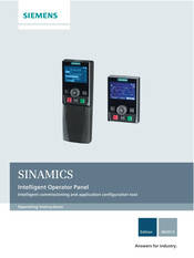
Siemens Sinamics ET 200pro FC-2 Operating Instructions Manual (118 pages)
Intelligent Commissioning and Application Configuration Tool
Brand:
Siemens
| Category:
Control Panel
| Size: 8.7 MB
Table of Contents
Table of Contents
5
1 Safety Notes
9
2 Overview
11
Introduction
11
Layout and Functions
12
Screen Icons
15
Menu Structure
16
3 Installation
17
Fitting the IOP
17
Initial Set-Up
18
User Definable Labels for the Status Screen
22
Firmware and Language Upgrade
23
4 Wizards
25
Example Wizard
31
Basic Commissioning with IOP
33
Wiring Diagrams
36
5 Control
45
Custom Hand Mode
49
Startup in Hand Mode
53
Hand/Auto Disable
54
6 Menu
57
Overview
57
Diagnostics
58
Parameters
62
Up/Download
68
Custom Parameter Sets
69
Extras
73
I/O Editor
85
Write Protection
87
Know-How Protection
89
7 Options
105
Door Mounting Kit
105
Hand-Held Device
107
Advertisement
Related Products
Siemens simovert master drive
Siemens SINAMICS Series
Siemens SITOP solar
Siemens SED2-1.5/22X
Siemens SED2-7.5/35B
Siemens SED2-3/35X
Siemens SED2-5.5/45X
Siemens SED2-3/42X
Siemens SED2-1.5/42X
Siemens SED2-18.5/35X
Siemens Categories
Industrial Equipment
Controller
Control Unit
Oven
Washer
More Siemens Manuals
Login
Sign In
OR
Sign in with Facebook
Sign in with Google
Upload manual
Upload from disk
Upload from URL