Sign In
Upload
Manuals
Brands
Respironics Manuals
Medical Equipment
ESPRIT
Respironics ESPRIT Manuals
Manuals and User Guides for Respironics ESPRIT. We have
2
Respironics ESPRIT manuals available for free PDF download: Service Manual, Operator's Manual
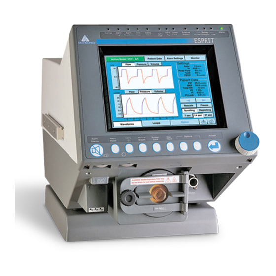
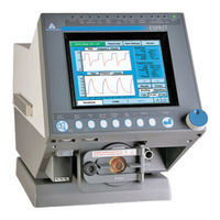
Respironics ESPRIT Service Manual (329 pages)
Ventilator
Brand:
Respironics
| Category:
Medical Equipment
| Size: 6.91 MB
Table of Contents
Table of Contents
3
Introduction and Intended Use
9
Recommended Tools and Test Equipment
10
Warnings and Cautions
13
General Warnings and Cautions
13
Theory of Operation
15
Pneumatic System
15
Delivery System
17
Ventilator System Electronics
23
Main PCB
26
Cpu Pcb
26
Analog PCB
27
Digital PCB
27
VGA Controller PCB
27
Blower Controller PCB
27
Motor Controller Pcbs
28
Sensor PCB
28
Man-Machine Interface (MMI) PCB
29
Power Supply
29
Backlight Inverter PCB
29
Real-Time Clock Battery
29
Backup Battery
29
External Battery
30
DC/DC Converter PCB (Use with Original 10.4-In. Displays Only)
30
Optical Rotary Encoder
30
Graphic User Interface (GUI)
30
Remote Alarm (Nurse Call)
31
Periodic Maintenance
33
Repair
35
Entering Diagnostic Mode
36
User Configuration
36
Changing the Date and Time
37
Setting the Time Format
37
Altitude
37
Compliance Enable
37
Backup Battery/Confirmation
38
Short Self Test (SST)
38
Extended Self Test (EST)
40
Software Screen
42
Diagnostic Codes
42
Hardware Diagnostics
44
Flow Control Hardware
45
Voltage Control Hardware
45
On/Off Hardware
46
Solenoid Hardware
46
Status Displays
46
Pneumatic Component Troubleshooting
47
Oxygen Valve
48
Oxygen Flow Sensor
49
Oxygen Regulator
51
Air Valve
52
Air Flow Sensor
53
Inhalation and Exhalation Solenoids
54
Safety Valve and Safety Solenoid
54
Pressure Relief Valve
55
Crossover Solenoid
56
Exhalation Flow Sensor
57
Check Valve 3
58
Check Valve 4
59
Filter Heater
60
Blower
60
Inhalation/ Exhalation Pressure Transducers and Exhalation Valve
61
Oxygen Pressure Switch
63
External Oxygen Sensor
63
Bacteria Filter Back Pressure Test
64
Diagnostic Codes
67
Diagnostic Code 1012 Troubleshooting
89
Ventilator Communications
95
Downloading Software
95
Programming the Ventilator Serial Number
98
Enabling Options
99
Setting up the Serial Interface for DRPT
100
Analog Output Port (Chart Recorder) Pinout
106
Performance Verification
107
Required Test Equipment
109
Preliminary Cleaning, Inspection and Setup
110
Preliminary Pneumatic Calibration Analyzer Setup
112
Certifier FA Plus Setup
112
Measurement Selection Screen
112
Averaging Setup Menu
114
Trigger Options Menu
115
Configuration Menu
116
Saving Configurations
116
Performance Verification Procedures
119
Electrical Safety (Test 1)
119
Extended Self Test (EST) (Test 2)
120
Air Flow Accuracy (Test 3)
122
Oxygen Flow Accuracy (Test 4)
124
Pressure Accuracy (Test 5)
126
PEEP System (Test 6)
127
Breath Rate (Test 7)
130
Alarm/Analog Output Signals, Alarm Volume, and Remote Alarm (Test 8)
131
Gas Volume Accuracy (Test 9)
134
Oxygen Accuracy (Test 10)
137
Heated Exhalation Bacteria Filter, Power Fail Alarm, and Display Intensity (Test 11)
140
Neonatal Option Testing (Test 12)
142
Backup Battery and External Battery (Test 13)
144
Returning Ventilator to Operation
146
Performance Verification Troubleshooting/Repair
147
Test 1: Electrical Safety
148
Test 2: Extended Self Test
148
Test 3: Air Flow Accuracy
149
Test 4: Oxygen Flow Accuracy
149
Test 5: Pressure Accuracy
150
Test 6: PEEP System
150
Test 7: Breath Rate
150
Test 8: Alarm Output Signal, Volume, and Remote Alarm
151
Test 9: Gas Volume Accuracy
151
Test 10: Oxygen Accuracy
151
Test 11: Heated Exhalation Bacteria Filter, Power Failure Alarm, and Display Intensity
152
Test 12: Neonatal Option Test
152
Test 13: Backup Battery and External Battery Test
153
Electrical Safety/Extended Self Test (EST) Data Form
157
Performance Verification Data Form
158
Component Removal/Installation
168
Filter Replacement
169
Top Enclosure
170
Sensor PCB
171
Backlight Inverter PCB (9.5-In. GUI)
174
Backlight Inverter PCB (Original 10.4-In. GUI Only)
174
DC/DC Converter PCB (Original 10.4-In. GUI Only)
175
Power Supply
176
Power Supply Fuses
179
MMI PCB (9.5-In. GUI)
181
MMI PCB (10.4-In. GUI)
184
GUI Assembly (9.5-In. GUI)
185
GUI Assembly (Original 10.4-In. GUI)
185
GUI Assembly (2Nd Generation 10.4-In. GUI)
189
Intensity and Volume Potentiometers (9.5-In. GUI)
191
Intensity and Volume Potentiometers (10.4-In. Gui's)
192
Rotary Encoder (9.5-In. GUI)
193
Rotary Encoder (10.4-In. Gui's)
194
GUI Front Panel Overlay (10.4-In. Gui's)
195
VGA Display Assembly (9.5-In. GUI)
196
Touch Screen/Led Indicator Assembly and Front Panel Overlay (9.5-In. GUI)
197
Transition PCBA, LCD, IR Touch Frame, and Backlight Inverter PCB
199
(2Nd Generation 10.4-In. GUI)
199
GUI Cleaning and Dust Gasket Installation (2Nd Generation 10.4-In. GUI)
201
Increased Minimum Alarm Volume Harness
204
Backup Alarm
204
AC Distribution Panel
205
AC Cord Bracket
207
Humidifier Receptacle Rotation
208
Printed Circuit Boards (Daughter Pcbs) (Except Main PCB)
210
Main PCB
213
Remote Alarm Jack
215
Power Switch
216
FIO 2 Connector
216
Exhalation Flow Sensor
218
Exhalation Valve Assembly
219
Primary Alarm
222
Filter Heater Assembly
222
Oxygen Flow Sensor
223
Inspiratory Manifold Assembly
225
Installing the Cable Extension Kit
227
Three-Station Solenoid Assembly
230
Air Flow Sensor
231
Air Valve Assembly
232
Oxygen Valve Assembly
233
Oxygen Regulator Assembly (with Oxygen Pressure Switch)
235
Elapsed Time Meter
237
Blower Motor Controller PCB (Original)
239
Blower Motor Controller PCB (Updated)
240
Blower Assembly
240
Blower Muffler Assembly
243
Cooling Fan/Cooling Coil Assembly
245
GUI Upgrades
247
Replacing the GUI (9.5-In. to Original 10.4-In.)
250
Installing the CPU and DC/DC Converter Pcbs
253
Downloading Ventilator Software
253
Calibrating the Screen
254
Enabling Options
254
Final Checkout
254
Replacing the GUI (9.5-In. to 2Nd Generation 10.4-In.)
254
Installing the CPU PCB
256
Downloading Ventilator Software
256
Calibrating the Screen
256
Enabling Options
257
Final Checkout
257
Replacing the GUI (Original 10.4-In. to 2Nd Generation 10.4-In)
257
Installing the CPU PCB
261
Downloading Ventilator Software
262
Calibrating the Screen
262
Enabling Options
262
Final Checkout
262
Where to Go for Help
263
Esprit Ventilator Replacement Parts List
265
Esprit Electronics
266
GUI Assembly
267
Oxygen Pneumatics
269
Air Pneumatics
271
Exhalation Pneumatics
273
Inspiratory Pneumatics
274
Back Panel
275
LX-200 Cart
276
Service Part Inventory List
277
Complete Repair Parts List
280
Pneumatic Schematics for EST
295
Block Patient Wye (Test 1, Step 2
295
Block Patient Wye (Test 1, Step 3
296
Block Patient Wye (Test 1, Step 4
297
Block Patient Wye (Test 1, Step 5
298
Safety Valve (Test 2, Step 1
299
Safety Valve (Test 2, Step 2
300
Blower (Test 3, Step 1
301
Blower (Test 3, Step 2
302
Oxygen Supply (Test 4, Step 1
303
Oxygen Supply (Test 4, Step 2
304
Crossover Circuit (Test 5, Step 1
305
Crossover Circuit (Test 5, Step 2
306
Crossover Circuit (Test 5, Step 3
307
Oxygen Delivery (Test 6, Step 1
308
Oxygen Sensor (Test 7, Step 1
309
Air Delivery (Test 8, Step 1
310
Pressure Relief Valve (Test 9, Step 1
311
Exhalation Valve (Test 10, Step 1
312
Exhalation Valve (Test 10, Step 2
313
Patient Circuit (Test 11, Step 1
314
Patient Circuit (Test 11, Step 2
315
Heated Filter (Test 12, Step 1
316
Heated Filter (Test 12, Step 2
317
Field Communications
319
Respi-Link
321
Index
323
Advertisement
Respironics ESPRIT Operator's Manual (312 pages)
Brand:
Respironics
| Category:
Fan
| Size: 5.6 MB
Table of Contents
Table of Contents
5
Introduction and Intended Use
11
Warnings, Cautions and Notes
13
Summary of Warnings, Cautions, and Notes
13
Symbols
23
Getting Started
27
Unpacking
27
Inspection
28
List of Parts and Accessories
28
Repacking
30
Inspiratory Bacteria Filter Installation
31
Heated Expiratory Bacteria Filter Installation
32
Oxygen Source Connection
34
Patient Circuit Flex Arm Installation
36
Ventilator Positioning
37
Setup
39
Back Panel Connections & Controls
39
Connecting AC Power Cord
41
Power On/Off
43
Entering Diagnostic Mode
44
User Configuration Screen
45
Backup Battery
50
Extended Self Test (EST)
51
Connecting Additional Equipment
53
Communication Interface
53
Connecting Serial Communications Devices
54
Connecting Remote Alarm Port
54
Connecting Humidifier
55
Connecting the Patient Circuit
57
Connecting the Analog Port
60
Operating Theory
61
Introduction
61
System Overview
61
Ventilator Breath Types
61
Ventilation Modes Common to VCV and PCV
62
Ventilation Modes Common to NPPV
66
Emergency Modes of Ventilation
67
Operating Instructions
69
Esprit Overview
69
The Front Panel
71
Ventilator Screens
77
Settings Screens
80
Selecting a New Ventilation Breath Type (VCV, PCV, or NPPV)
89
Selecting the Mode (A/C-SIMV-CPAP or Spont-Spont/T)
92
Apnea Ventilation
93
Patient Data Screen
94
Monitor Screen
95
Special Procedures
97
Preoperational Procedure
98
Alarm Testing Procedure
100
Where to Go for Help
100
Alarms
101
Introduction
101
Visual Alarms
101
Audible Alarms
102
Alarm Reset
103
Alert Messages
104
Alarm Indicators
108
Care and Maintenance
111
General Information
111
Cleaning
111
Sterilization
112
Bacteria Filters
114
Periodic Maintenance
117
Storage
121
Repairs
121
Weee/Rohs Recycling Directives
121
Diagnostics
123
Entering Diagnostic Mode
124
Diagnostic Functions
125
Extended Self Test (EST)
126
Self Test
132
Technical Specifications
135
Breath Types
135
Modes
135
Volume Ventilation Settings, Ranges & Resolution
135
Pressure Control Ventilation Settings, Ranges & Resolution
136
Non-Invasive Positive Pressure Ventilation Settings, Ranges & Resolution
137
Apnea Ventilation
137
Value Entry Message
138
Patient Data Screen
139
Front Panel Keys
140
Level Controls
141
Calculated Values from Expiratory Hold Maneuver
141
Interface Ports
141
Environmental Specifications
141
Environmental Protection
142
Alarms
142
Connectors
143
Filters
143
Measuring and Display Devices
144
AC Power & Battery Indicators
144
Leakage Current
144
Compliance and Approvals
145
Power Requirements
145
Dimensions and Weights
145
Electromagnetic Compatibility Declaration
146
Pneumatic System
151
Labels
152
Options and Accessories
155
Introduction
155
Oxygen Sensor Option
157
Assemble O2 Sensor
157
Attaching the Sensor to the Ventilator
158
Warranty
159
Sensor Tee
159
Battery Option
161
Warranty
168
Warnings, Cautions and Notes for the Backup Battery
168
External Battery Option
171
Installation
172
Power Consumption Sequence
172
External Battery/Backup Battery Operation
172
Battery Capacity
174
Battery Charging
174
Testing
175
Battery Specifications
175
Warranty
176
Oxygen Manifold Option
177
Kit Contents
177
Tools Needed
177
Assembly Instructions
178
Replacement Parts
182
Using the Manifold
182
Graphics
184
Starting Graphics
184
Using Graphics
184
Replotting and Scrolling
185
Rescaling the Display
185
Freeze Feature
187
Save and Overlay Features
188
Inspiratory Area
189
Alarms During Graphics
190
Esprit Communications Option (Com1)
192
Print Screen
192
Vuelink Compatibility
194
Configuring the Vuelink Module
195
Analog Output (Chart Recorder)
201
Communications Option 2 (Com2)
204
RS-232 Configuration
204
Commands Transmitted to the Ventilator
205
Transmission of Data from the Ventilator
205
SNDA<CR>, Send Variable Length Ventilator Settings Report
205
Respiratory Mechanics Option
217
Accessing Respiratory Mechanics Data
217
Vital Capacity Maneuver
218
MIP/P0.1 Maneuver
220
Static C and R Maneuver
222
Alarms and Error Messages
224
Static Compliance
230
Static Resistance
230
Compliance (C) and Resistance (R) Computations
231
Dynamic Compliance
231
Dynamic Resistance
231
Peak Lung Flow
231
Trending Option
235
Accessing Trending Data
235
Selecting Parameters for Display
237
Using the Manual Rescale Function
239
Changing the Cursor Position
240
Selecting the Time Scale
241
Using the +2 Hrs/-2 Hrs Buttons
242
Using the Zoom Function
242
Using the Rescale Button
242
Using the View 1/View 2 Buttons
243
Using the Clear Button
243
Alarms During Trending
243
PCMCIA Card
243
Trending Not Available
244
Specifications
244
Flow-Trak ® Option
249
On the Screen
250
Breath Delivery
251
Inspiratory Hold
251
Respiratory Mechanics
251
Alarms
252
NICO-Esprit Interface Option
253
System Requirements
253
Setup
254
Communications
257
Trended NICO Data
258
Troubleshooting
261
Neonatal Option
265
System Requirements
265
Changing Patient Types
266
Percent Leak
269
Patient Leak Values
269
Communications Protocol
271
RS-232 Configuration
271
Commands Transmitted to the Ventilator
271
Transmission of Data from the Ventilator
271
Ventilator Report Command and Response (VRPT
271
Volume Control Ventilation Settings Report (VCVS
281
Pressure Control Ventilation Settings Report (PCVS
284
Non-Invasive Positive Pressure Ventilation Settings Report (NPVS
286
Patient Data Report (PTDT
288
Alarm Status Report (ALRM
292
Unrecognized Commands
294
Customer Service & Warranty
295
Customer Service
295
Warranty
295
Options and Accessories
296
Alarm Testing Procedure
298
Glossary
301
Abbreviations
301
Definitions
304
Advertisement
Related Products
Respironics EverFlo
Respironics EverGo
Respironics EverGo Portable Oxygen Concentrator
Respironics 1002720
Respironics 1002801
Respironics 1009044
Respironics 1009045
Respironics 1009046
Respironics 1009047
Respironics 1009048
Respironics Categories
Medical Equipment
Respiratory Product
Humidifier
Fan
Oxygen Equipment
More Respironics Manuals
Login
Sign In
OR
Sign in with Facebook
Sign in with Google
Upload manual
Upload from disk
Upload from URL