Table of Contents
Advertisement
Quick Links
Advertisement
Table of Contents
Troubleshooting

Subscribe to Our Youtube Channel
Related Manuals for Respironics ESPRIT


Summary of Contents for Respironics ESPRIT
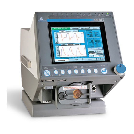
- Page 1 ESPRIT Ventilator ® S e r v i c e M a n u a l REF 580-1000-02 G...
- Page 2 This work is protected under Title 17 of the United States copyright code and is the sole property of Respironics. No par of this document may be copied or otherwise reproduced, or stored in any electronic information retrieval system, except as specifically permitted under United States copyright law, without the prior written consent of Respironics.
-
Page 3: Table Of Contents
Backup Battery/Confirmation ........5-4 REF 580-1000-02 G Esprit® Ventilator Service Manual © Respironics, Inc. - Page 4 Setting Up the Serial Interface for DRPT ......7-6 Esprit® Ventilator Service Manual © Respironics, Inc.
- Page 5 Test 12: Neonatal Option Test ........8-46 REF 580-1000-02 G Esprit® Ventilator Service Manual © Respironics, Inc.
- Page 6 Exhalation Flow Sensor ......... 9-51 Esprit® Ventilator Service Manual © Respironics, Inc.
- Page 7 Esprit Electronics ........
- Page 8 Index ..........I-1 Esprit® Ventilator Service Manual © Respironics, Inc.
-
Page 9: Introduction And Intended Use
It is intended for use by qualified medical personnel to provide continuous or intermittent ventilatory support for adult and pediatric patients as prescribed by a physician. The Esprit Ventilator is intended for use in either invasive or non-invasive applications. -
Page 10: Recommended Tools And Test Equipment
Introduction and Intended Use Recommended Tools The following table lists the recommended tools, test equipment, and and Test Equipment materials required to service and maintain the Esprit Ventilator (Table 1-1). Test equipment must meet the requirements in Table 1-2. Description Manufacturer and Model... - Page 11 Required: Windows 95 or later, serial port and software) CD ROM drive ESD-safe field service vacuum cleaner 3M model 497-AJM or equivalent Table 1-1: Recommended Test Equipment, Tools, and Materials REF 580-1000-02 G Esprit® Ventilator Service Manual © Respironics, Inc.
- Page 12 0 to 10 L STP ± 2% of reading ± 0.20 L STP Voltage DC: ± 5 to 50 V ± 2% of reading AC: 2 to 300 V Table 1-2: Test Equipment Specifications Esprit® Ventilator Service Manual © Respironics, Inc. REF 580-1000-02 G...
-
Page 13: Warnings And Cautions
CAUTION: Use only Respironics Esprit repair/service parts. Only Respironics parts are designed for use in this ventilator. Use of non-Respironics repair parts may alter ventilator reliability resulting in damage. Use of non- Respironics repair parts will affect your warranty. Contact Customer Service at 1-800-345-6443 or 724-387-4000 for more information. - Page 14 CAUTION: Always ensure that you are following proper electrostatic discharge (ESD) grounding procedures before handling static-sensitive devices. CAUTION: Be careful not to pull or crimp any cables, tubes or wires. Esprit® Ventilator Service Manual © Respironics, Inc. REF 580-1000-02 G...
-
Page 15: Theory Of Operation
The Esprit Ventilator includes a graphic user interface (GUI), internal blower, and inspiratory module that mixes air and oxygen. The ventilator can operate from a 40 to 90 psig (276 to 620 kPa) medical grade oxygen source for enriched oxygen operation. - Page 16 Expiratory Exhalation Exhalation Room Flow Filter Valve Sensor Assembly Figure 3-1: Pneumatic System Block Diagram Figure 3-2 shows the Esprit ventilator pneumatic system and its components. Figure 3-2: Pneumatic Schematic Esprit® Ventilator Service Manual © Respironics, Inc. REF 580-1000-02 G...
-
Page 17: Delivery System
Blower speed is automatically adjusted to account for differences in gas density due to altitude. The altitude can be adjusted from the hardware screen in diagnostics mode. The High Pressure alarm limit setting also affects blower speed. REF 580-1000-02 G Esprit® Ventilator Service Manual © Respironics, Inc. - Page 18 PS1 opens if measured pressure is less than 35 psig (241.3 kPa). If the oxygen supply pressure switch opens during normal ventilation (at O > 21%), a Low O Supply alarm results. Esprit® Ventilator Service Manual © Respironics, Inc. REF 580-1000-02 G...
- Page 19 During a high priority alarm condition such as an occlusion or ventilator failure mode (VENT INOP), SOL2 is deenergized to open the safety valve and allow the patient to breathe room air. REF 580-1000-02 G Esprit® Ventilator Service Manual © Respironics, Inc.
- Page 20 It is also used with the exhalation pressure transducer to detect patient circuit occlusions. Esprit® Ventilator Service Manual © Respironics, Inc. REF 580-1000-02 G...
- Page 21 SOL3 is energized, venting the transducer to atmosphere. This occurs during POST, at the beginning of a breath one minute after POST, six minutes after POST, eleven minutes after POST, and hourly thereafter. REF 580-1000-02 G Esprit® Ventilator Service Manual © Respironics, Inc.
- Page 22 A thermistor in the flow sensor measures the temperature of the gas and provides the microprocessor with information to compensate the measured flow. Esprit® Ventilator Service Manual © Respironics, Inc. REF 580-1000-02 G...
-
Page 23: Ventilator System Electronics
CPU controls the flow, pressure, and volume of air and oxygen to be delivered to the patient. The CPU also monitors alarms and independently monitors software execution. REF 580-1000-02 G Esprit® Ventilator Service Manual © Respironics, Inc. - Page 24 CPU. Ventilator data from the CPU is conditioned by the VGA and man-machine interface (MMI) PCBs, then displayed on an LCD. The following table summarizes the electronic signal path for Esprit components. Component Signal Path Sequence...
- Page 25 Backlight inverter PCB potentiometer (10.4-in. display) VGA display (9.5-in. display) MMI PCB, main PCB, VGA controller PCB, CPU PCB VGA display (10.4-in. display) Main PCB, VGA controller PCB, CPU PCB 3-11 REF 580-1000-02 G Esprit® Ventilator Service Manual © Respironics, Inc.
-
Page 26: Main Pcb
169-msec watchdog timer that monitors software operation. • Data address and control bus to the main PCB. • Current version includes 2 MB memory capacity (previous versions included 1 and 1.5, MB). 3-12 Esprit® Ventilator Service Manual © Respironics, Inc. REF 580-1000-02 G... -
Page 27: Analog Pcb
If the blower motor stops running, the lockup sensing circuit shuts off power to the blower. 3-13 REF 580-1000-02 G Esprit® Ventilator Service Manual © Respironics, Inc. -
Page 28: Motor Controller Pcbs
MMI PCB: +5 V under MMI PCB: +5 V over Power supply: +10 V under Power supply: +10 V over Main PCB: +5 V over Main PCB: +5 V under Power fail 3-14 Esprit® Ventilator Service Manual © Respironics, Inc. REF 580-1000-02 G... -
Page 29: Man-Machine Interface (Mmi) Pcb
VGA controller PCB when ventilator power is off. Backup Battery The optional Backup Battery can power the ventilator for approximately 30 minutes under nominal settings if AC power is lost. 3-15 REF 580-1000-02 G Esprit® Ventilator Service Manual © Respironics, Inc. -
Page 30: External Battery
Graphic User Interface (GUI) Esprit ventilators include a 9.5-in. monochrome or 10.4-in. color-capable liquid crystal display (LCD) screen. The 9.5-in. LCD is a monochrome 640 x 480 active matrix display. The 10.4-in LCD is a color 640 x 480 active matrix display capable of operating in monochrome or color mode. -
Page 31: Remote Alarm (Nurse Call)
• The ventilator runs POST. NOTE: To connect the Lifecare remote alarm system to an Esprit ventilator, a DB15 to BNC cable adapter must be installed into the analog output port. 3-17 REF 580-1000-02 G Esprit® Ventilator Service Manual © Respironics, Inc. - Page 32 Chapter 3 Theory of Operation (This page is intentionally blank.) 3-18 Esprit® Ventilator Service Manual © Respironics, Inc. REF 580-1000-02 G...
-
Page 33: Periodic Maintenance
CAUTION: Do not operate the Esprit Ventilator without a properly functioning expiratory filter and heater. Doing so may cause damage to delicate ventilator components, such as the expiratory flow sensor, which may lead to inaccurate spirometry or a Vent Inop condition. - Page 34 • Backup Battery • If you have the backup battery option, refer to section 13 of the Operator’s Manual for charging and maintenance instructions Table 4-1: Schedule for Periodic Maintenance Esprit® Ventilator Service Manual © Respironics, Inc. REF 580-1000-02 G...
-
Page 35: Repair
Chapter 5. Repair This section describes the Esprit Ventilator’s diagnostic mode and other repair procedures. Diagnostic mode allows you to: • Run short self test (SST). • Run an extended self test (EST). • Check the software revision of the ventilator and installed options. -
Page 36: Entering Diagnostic Mode
Chapter 5 Repair Entering Diagnostic To start Esprit ventilator diagnostics, simultaneously press the ALARM RESET and 100% O keys on the front panel for approximately five seconds while Mode turning ventilator power on. At the prompt, touch OK to enter diagnostic mode (Figure 5-1). -
Page 37: Changing The Date And Time
Enabling compliance correction improves the accuracy of volume delivery during normal operation. • Disabling compliance correction means that tubing compliance volume is not added to delivered volumes. Compliance correction is typically disabled during performance testing. REF 580-1000-02 G Esprit® Ventilator Service Manual © Respironics, Inc. -
Page 38: Backup Battery/Confirmation
(even though compliance correction appears enabled). Backup Battery/ If the backup battery is installed, the operator can have the Esprit confirm the backup battery is connected each time that the machine powers on. Pressing Confirmation the BKUP BATTERY button (Figure 5-3) allows this confirmation feature, identified by an active button with a white background. - Page 39 • Touch RETEST to repeat the test. • Touch CONTINUE to skip the failed test. • Touch CANCEL to exit EST. Figure 5-5: Starting SST REF 580-1000-02 G Esprit® Ventilator Service Manual © Respironics, Inc.
-
Page 40: Extended Self Test (Est)
2. Connect the patient circuit to the ventilator. 3. Touch EST on the diagnostic screen (Figure 5-6). 4. Touch Start EST to begin the test. Figure 5-6: Starting EST Esprit® Ventilator Service Manual © Respironics, Inc. REF 580-1000-02 G... - Page 41 If any EST tests fail, the screen displays failure data, including diagnostic code, measured value, and passing values. • Touch RETEST to repeat the test. • Touch CONTINUE to skip the failed test. • Touch CANCEL to exit EST. REF 580-1000-02 G Esprit® Ventilator Service Manual © Respironics, Inc.
-
Page 42: Software Screen
Figure 5-7: Diagnostic Mode Software Screen Diagnostic Codes The Esprit Ventilator generates diagnostic codes when the microprocessor detects a fault during normal operation, or if a failure occurs during SST or EST. Section 6 lists diagnostic codes, and recommended repair procedures for each code. - Page 43 4xxx: Continuous built-in test failure (failures during normal ventilation). 5xxx: Safety valve open/Backup battery not connected. 6xxx: Not used. 7xxx: Power supply failure. 8xxx: Software diagnostic information. 9xxx: Sensor/internal communication fault. REF 580-1000-02 G Esprit® Ventilator Service Manual © Respironics, Inc.
-
Page 44: Hardware Diagnostics
Incrementally open and close the exhalation valve. • Set various analog and digital voltages. • Control power to the blower, filter heater, and 24-V components. • Exercise the solenoids. • View hardware status. 5-10 Esprit® Ventilator Service Manual © Respironics, Inc. REF 580-1000-02 G... -
Page 45: Flow Control Hardware
0 to 5 V, and compare it to the ADC output voltage shown in the Voltage Wrap status display. • The Blower button allows you to adjust blower voltage from 0 to 5 V. 5-11 REF 580-1000-02 G Esprit® Ventilator Service Manual © Respironics, Inc. -
Page 46: On/Off Hardware
Exhalation Pressure displays the pressure measured by the exhalation pressure sensor. • Oxygen Supply displays whether the oxygen inlet pressure switch detects an external oxygen source connected to the ventilator. 5-12 Esprit® Ventilator Service Manual © Respironics, Inc. REF 580-1000-02 G... -
Page 47: Pneumatic Component Troubleshooting
4. Touch the Hardware button to view the hardware screen. NOTE: These troubleshooting procedures assume that all hardware begins in an initialized state (all adjustable parameters set to zero), including Blower 5-13 REF 580-1000-02 G Esprit® Ventilator Service Manual © Respironics, Inc. -
Page 48: Oxygen Valve
2001 - 4000 ft. 1145 - 1540 steps 4001 - 6000 ft. 1120 - 1505 steps 6001 - 8000 ft. 1090 - 1470 steps 8001 - 10,000 ft. 1060 - 1435 steps 5-14 Esprit® Ventilator Service Manual © Respironics, Inc. REF 580-1000-02 G... -
Page 49: Oxygen Flow Sensor
Return the hardware screen to its initialized state. Figure 5-10: Diagnostic Mode - Hardware Screen (Safety Solenoid Energized) Oxygen Flow Sensor 1. Connect the oxygen source to the ventilator. 5-15 REF 580-1000-02 G Esprit® Ventilator Service Manual © Respironics, Inc. - Page 50 Flow to: Flow Displays Read: 5 LPM 4.5 to 5.5 LPM 10 LPM 9 to 11 LPM 20 LPM 18 to 22 LPM 50 LPM 45 to 55 LPM 5-16 Esprit® Ventilator Service Manual © Respironics, Inc. REF 580-1000-02 G...
-
Page 51: Oxygen Regulator
4. Connect the gauge to the oxygen valve pressure port (Figure 5-12). Oxygen valve Connection to oxygen valve pressure port Figure 5-12: Oxygen High Pressure Connection 5. Touch Blower to de-energize (gray background) the blower. 5-17 REF 580-1000-02 G Esprit® Ventilator Service Manual © Respironics, Inc. -
Page 52: Air Valve
5. Touch Air and set the flow to 1 LPM. 6. Check that the Air Position display is between 215 and 525 steps. 7. Touch Air and set the flow to 180 LPM. 5-18 Esprit® Ventilator Service Manual © Respironics, Inc. REF 580-1000-02 G... -
Page 53: Air Flow Sensor
90 to 110 LPM 120 LPM 108 to 132 LPM 165 LPM 148.5 to 181.5 LPM 0 LPM 0 ± 0.1 LPM 6. Return the hardware screen to its initialized state. 5-19 REF 580-1000-02 G Esprit® Ventilator Service Manual © Respironics, Inc. -
Page 54: Inhalation And Exhalation Solenoids
4. Check that the Inhalation Pressure display reads 0 ± 0.1 cmH 5. Touch Safety to energize (white background) the safety solenoid. 6. Check that the Inhalation Pressure display is greater than 30 cmH 5-20 Esprit® Ventilator Service Manual © Respironics, Inc. REF 580-1000-02 G... -
Page 55: Pressure Relief Valve
4. Touch Exhalation and set it to 2000 steps. 5. Touch Air and set the flow to 1 LPM. 6. Check that the analyzer reads 130-140 cmH O. If not, adjust the relief pressure (Figure 5-14): 5-21 REF 580-1000-02 G Esprit® Ventilator Service Manual © Respironics, Inc. -
Page 56: Crossover Solenoid
3. Connect patient circuit to ventilator and block wye with a cork. 4. Touch Safety to energize (white background) the safety solenoid. 5. Touch Exhalation and set it to 2000 steps. 5-22 Esprit® Ventilator Service Manual © Respironics, Inc. REF 580-1000-02 G... -
Page 57: Exhalation Flow Sensor
Exhalation Flow Sensor 1. Connect the patient tubing from the ventilator to the high flow port of a calibrated analyzer (Figure 5-15). Figure 5-15: Exhalation Flow Sensor Troubleshooting Setup 5-23 REF 580-1000-02 G Esprit® Ventilator Service Manual © Respironics, Inc. -
Page 58: Check Valve 3
30 cmH 10. Check that the Air Flow display on the hardware screen reads 0 ± 0.1 LPM. 11. Return the hardware screen to its initialized state. 5-24 Esprit® Ventilator Service Manual © Respironics, Inc. REF 580-1000-02 G... -
Page 59: Check Valve 4
3. Gently inhale from the bacteria filter. 4. Check that the Exhalation Flow display on the hardware screen reads 0 ± 0.1 LPM. 5. Return the hardware screen to its initialized state. 5-25 REF 580-1000-02 G Esprit® Ventilator Service Manual © Respironics, Inc. -
Page 60: Filter Heater
6. Check that the analyzer reads 148.5 to 181.5 LPM. 7. Touch Blower to turn off the blower (gray background). 8. Check that the blower stops and the analyzer reads 0 ± 0.1 LPM. 5-26 Esprit® Ventilator Service Manual © Respironics, Inc. REF 580-1000-02 G... -
Page 61: Inhalation/ Exhalation Pressure Transducers And Exhalation Valve
9. Return the hardware screen to its initialized state. Figure 5-16: Blower Troubleshooting Setup Inhalation/ Exhalation Pressure Transducers and Exhalation Valve 1. Connect patient circuit with tee to the ventilator. 5-27 REF 580-1000-02 G Esprit® Ventilator Service Manual © Respironics, Inc. - Page 62 ± 10% of the analyzer display. 9. Unblock the tee and verify that the inhalation, exhalation, and analyzer pressure displays read 0 ± 0.1 cmH 5-28 Esprit® Ventilator Service Manual © Respironics, Inc. REF 580-1000-02 G...
-
Page 63: Oxygen Pressure Switch
Power Supply: +10 V over Replace Power Supply Main PCB: +5 V over Replace Main PCB Main PCB: +5 V under Replace Main PCB Power Fail Replace Power Supply 5-29 REF 580-1000-02 G Esprit® Ventilator Service Manual © Respironics, Inc. -
Page 64: Bacteria Filter Back Pressure Test
The back pressure for a new filter is typically 2.5 A back pressure over 4 cmH O indicates an occluded filter. The filter fails the test if the back pressure is greater than 4 cmH 5-30 Esprit® Ventilator Service Manual © Respironics, Inc. REF 580-1000-02 G... - Page 65 Hardware screen. 3. Confirm that the Internal Oxygen display on the Hardware screen is between 0.52 to 0.62 V. If the display is outside this range, replace the sensor PCB. 5-31 REF 580-1000-02 G Esprit® Ventilator Service Manual © Respironics, Inc.
- Page 66 Chapter 5 Repair (This page is intentionally blank.) 5-32 Esprit® Ventilator Service Manual © Respironics, Inc. REF 580-1000-02 G...
-
Page 67: Diagnostic Codes
Chapter 6. Diagnostic Codes The Esprit Ventilator generates diagnostic codes when the microprocessor detects a fault during normal operation, or if a failure occurs during SST or EST. Table 6-1 lists diagnostic codes, and recommended repair procedures for each code. Perform the repair procedures in the order listed until the problem is resolved. - Page 68 < 150 or > 500 (DRPT) command to obtain detailed steps (default = 280 steps). information. 2. If step position during liftoff is outside range, replace oxygen valve. 3. Replace oxygen motor controller PCB. Esprit® Ventilator Service Manual © Respironics, Inc. REF 580-1000-02 G...
- Page 69 4. Check CV3 (Chapter 5). Replace as not drop below 35 cmH O. This necessary. code indicates that circuit pressure 5. Check tubing from inspiratory was <35 cmH solenoid to inspiratory manifold. REF 580-1000-02 G Esprit® Ventilator Service Manual © Respironics, Inc.
- Page 70 3. Replace exhalation filter and rerun The ventilator starts a 5 LPM air test. flow, and the inspiratory pressure transducer (PT3) should measure >10 cmH O. This code indicates that PT3 is measuring <10 cmH Esprit® Ventilator Service Manual © Respironics, Inc. REF 580-1000-02 G...
- Page 71 This code indicates that information 2. Replace CPU PCB. stored on FS3 cannot be read. 3. Replace exhalation flow sensor. 4. Replace sensor PCB. 5. Replace analog PCB. 6. Replace main PCB. REF 580-1000-02 G Esprit® Ventilator Service Manual © Respironics, Inc.
- Page 72 5. Replace main to sensor cable. (PT3) and exhalation pressure 6. Replace analog PCB. transducer (PT2) are cross-checked. 7. Replace main PCB. This code indicates that the PT3 measurement was out of range. Esprit® Ventilator Service Manual © Respironics, Inc. REF 580-1000-02 G...
- Page 73 4. Check orientation of exhalation check with the exhalation valve open. This valve CV4. code indicates that the exhalation flow sensor (FS3) measurement is <90 LPM or >110 LPM, and the FS3 measurement is displayed. REF 580-1000-02 G Esprit® Ventilator Service Manual © Respironics, Inc.
- Page 74 100 LPM is created. The air flow sensor (FS1) should measure a flow of 0 LPM. This code indicates that FS1 measured >3 LPM. Esprit® Ventilator Service Manual © Respironics, Inc. REF 580-1000-02 G...
- Page 75 4. Replace the primary alarm to MMI for a response that alarm is audible. PCB cable. This code indicates that the primary 5. Replace MMI PCB. alarm is not working. 6. Replace main PCB. REF 580-1000-02 G Esprit® Ventilator Service Manual © Respironics, Inc.
- Page 76 1 LPM, the exhalation pressure transducer (PT2) should measure a stable pressure of 120-160 cmH2O within 60 seconds. This code indicates that PT2 measured >170 cmH 6-10 Esprit® Ventilator Service Manual © Respironics, Inc. REF 580-1000-02 G...
- Page 77 150 LPM is 4. Replace main PCB. established and compared to the exhalation flow sensor (FS3) reading. This code indicates that FS3 measurement difference was >20 LPM. 6-11 REF 580-1000-02 G Esprit® Ventilator Service Manual © Respironics, Inc.
- Page 78 10 LPM air flow starts while 4. Install safety valve kit. monitoring the inspiratory pressure 5. Replace inspiratory manifold transducer (PT3). This code assembly. indicates that PT3 is measuring >5 6-12 Esprit® Ventilator Service Manual © Respironics, Inc. REF 580-1000-02 G...
- Page 79 EEPROM from the connections. exhalation flow sensor (FS3). 3. Replace exhalation flow sensor. 4. Replace sensor PCB. 5. Replace CPU PCB. 6. Replace analog PCB. 7. Replace main PCB. 6-13 REF 580-1000-02 G Esprit® Ventilator Service Manual © Respironics, Inc.
- Page 80 4. Replace analog PCB. commanded to energize (open), and exhalation pressure transducer (PT2) should measure 0 cmH O. This code indicates that PT2 measured outside the range from -3 to 3 cmH 6-14 Esprit® Ventilator Service Manual © Respironics, Inc. REF 580-1000-02 G...
- Page 81 4. Replace CPU PCB. midpoint position (1000 ± 5 steps). 5. Replace main PCB. This code indicates that measured position was outside the range of 995 to 1005 steps. 6-15 REF 580-1000-02 G Esprit® Ventilator Service Manual © Respironics, Inc.
- Page 82 <10 cmH O as measured by inspiratory pressure transducer (PT3). This code indicates that PT3 measured a back pressure >10 6-16 Esprit® Ventilator Service Manual © Respironics, Inc. REF 580-1000-02 G...
- Page 83 5. Replace main to sensor cable. transducer (PT2) are cross-checked. 6. Replace analog PCB. This code indicates that the PT2 7. Replace main PCB. measurement was out of range. 6-17 REF 580-1000-02 G Esprit® Ventilator Service Manual © Respironics, Inc.
- Page 84 Three consecutive 4. Replace three-station solenoid failures result in a Vent Inop assembly. condition. 5. Replace main to sensor cable. 6. Replace analog PCB. 7. Replace main PCB. 6-18 Esprit® Ventilator Service Manual © Respironics, Inc. REF 580-1000-02 G...
- Page 85 PCB. sensor (FS2) still measures flow. 3. Replace oxygen valve assembly. 4. Replace oxygen flow sensor. 5. Replace oxygen flow sensor cable. 6. Replace main PCB. 6-19 REF 580-1000-02 G Esprit® Ventilator Service Manual © Respironics, Inc.
- Page 86 4. Replace main PCB. 4021* Exhalation motor error. 1. Replace exhalation motor controller PCB. Unexpected exhalation valve stepper 2. Replace exhalation valve assembly. motor reading. 3. Replace main PCB. 6-20 Esprit® Ventilator Service Manual © Respironics, Inc. REF 580-1000-02 G...
- Page 87 1. Perform the Air Flow Accuracy test. temperature outside range. 2. Verify cooling fans are functioning and are both installed in the proper orientation. 3. Replace exhalation flow sensor. 6-21 REF 580-1000-02 G Esprit® Ventilator Service Manual © Respironics, Inc.
- Page 88 MMI PCB +5V, connections. sensor PCB +5V, +12V, -12V, 24V, 2. Replace sensor PCB. and power fail failures. 3. Replace MMI PCB. 4. Replace power supply. 8xxx: Software Faults 6-22 Esprit® Ventilator Service Manual © Respironics, Inc. REF 580-1000-02 G...
-
Page 89: Diagnostic Code 1012 Troubleshooting
4. Replace the CPU PCB. 5. Replace the analog PCB. 6. Replace the main PCB. 9004 Pressure sensor failure. 1. Replace sensor PCB. A/D converter out of range. 2. Replace analog PCB. 6-23 REF 580-1000-02 G Esprit® Ventilator Service Manual © Respironics, Inc. - Page 90 Disregard an 8004 code without an accompanying 1012 code in the diagnostic log. Possible causes for a 1012 diagnostic code include: • The air valve opening position is too low or too high. 6-24 Esprit® Ventilator Service Manual © Respironics, Inc. REF 580-1000-02 G...
- Page 91 PCB is not functioning correctly. a. If you can hear the blower attempt to start running, and then the LED lights, replace the blower. 6-25 REF 580-1000-02 G Esprit® Ventilator Service Manual © Respironics, Inc.
- Page 92 (section 8): a. If the air flow accuracy test passes, replace the air valve. b. If the test fails, replace the air flow sensor. 6-26 Esprit® Ventilator Service Manual © Respironics, Inc. REF 580-1000-02 G...
- Page 93 6. With circuit pressure at the PRV cracking pressure, touch Exhalation and verify that the pressure displays drop to 0 ± 0.1 cmH immediately when energized (white background) and returns to circuit 6-27 REF 580-1000-02 G Esprit® Ventilator Service Manual © Respironics, Inc.
- Page 94 • If pressures remain higher on the same pressure display, replace the sensor PCB. 8. Return the INSP and EXH tubes to their correct positions on the sensor PCB. 6-28 Esprit® Ventilator Service Manual © Respironics, Inc. REF 580-1000-02 G...
-
Page 95: Ventilator Communications
• Generating a DRPT Downloading The CPU PCB in the Esprit Ventilator contains nonvolatile memory that allows the software to be upgraded electronically using a personal computer (PC) or Software laptop computer. If the CPU PCB is replaced, the serial number and any installed options (such as color or graphics) must be reprogrammed. - Page 96 Chapter 7 Ventilator Communications 3. The Esprit Setup screen appears (Figure 7-1). Click Next to continue or Cancel to exit. Figure 7-1: Esprit Setup Screen 4. The Select Language screen (Figure 7-2) appears. Select a language, then click Next to continue or Cancel to exit.
- Page 97 Initializing memory, please wait Initialization Complete Programming flow sensor tables, please wait Programming Complete 9. When the download is complete, click OK on the PC screen. The ventilator automatically reboots in diagnostics mode. REF 580-1000-02 G Esprit® Ventilator Service Manual © Respironics, Inc.
-
Page 98: Programming The Ventilator Serial Number
Chapter 7 Ventilator Communications 10. Touch the Software key on the ventilator screen. 11. Verify that the Flash Version is the same as the version on the Esprit software CD-ROM. IMPORTANT: Reset the altitude and turn compliance off then back on to reactivate compliance compensation (use the User Configuration Screen in diagnostic mode as described in Chapter 5). -
Page 99: Enabling Options
A warning to verify that no patient is connected. Touch OK to enter diagnostic mode. 2. With the Esprit software CD-ROM in the CD drive, click on Start > Run, then enter D:\setup.exe -snonly to begin a software download, where D: is the CD drive letter. -
Page 100: Setting Up The Serial Interface For Drpt
Figure 7-5: Parallel Port Adapter and Option Enable Button Setting Up the Serial Follow these steps to connect the Esprit Ventilator and a PC to create a diagnostic report (DRPT): Interface for DRPT 1. Connect a 9-pin male-female null modem RS-232 cable between the PC and Esprit ventilator. - Page 101 Programs > Accessories > Communications > HyperTerminal, then double-clicking on the HYPERTRM.EXE icon. 4. Enter a name for the connection (Esprit Communications is entered in Figure 7-6) and choose an icon, then click OK). Figure 7-6: Entering a Name for the Connection to the Esprit Ventilator 5.
- Page 102 6. Enter these settings for the serial port (Figure 7-8): Figure 7-8: Serial Port Settings 7. At the HyperTerminal window, click on File > Properties, the Settings tab (Figure 7-9), then ASCII Setup. Figure 7-9: HyperTerminal Settings Tab Esprit® Ventilator Service Manual © Respironics, Inc. REF 580-1000-02 G...
- Page 103 Ventilator Communications 8. Match the ASCII Setup screen (Figure 7-10), then select File > Save As and save to the desktop if you want to create an icon for Esprit Communications on the Windows desktop. Figure 7-10: ASCII Setup Screen REF 580-1000-02 G Esprit®...
- Page 104 Chapter 7 Ventilator Communications Generating a 1. With the Esprit ventilator in diagnostic mode and the null-modem serial cable connected, start HyperTerminal, open the Esprit Diagnostic Report Communications file, or click on the Esprit Communications icon on (DRPT) the PC (if created).
- Page 105 Air liftoff 180 to 500 steps Oxygen liftoff 150 to 500 steps • Certain diagnostic codes include additional debugging data. In case additional data is displayed, contact Respironics Customer Service for more information. 7-11 REF 580-1000-02 G Esprit® Ventilator Service Manual © Respironics, Inc.
-
Page 106: Analog Output Port (Chart Recorder) Pinout
Chapter 7 Ventilator Communications Analog Output Port The Communications Option allows the Esprit Ventilator to send ventilator data to a chart recorder or compatible patient monitoring systems using the analog (Chart Recorder) output port. Figure 7-12 summarizes the analog output port pinouts. -
Page 107: Performance Verification
Installation: Neonatal option Electrical Safety Neonatal option testing Removal/replacement: AC distribution panel Electrical Safety Removal/replacement: Power supply Electrical Safety Backup Battery and External Battery Table 8-2: Performance Verification Test Requirements REF 580-1000-02 G Esprit® Ventilator Service Manual © Respironics, Inc. - Page 108 Air flow accuracy Gas volume accuracy Removal/replacement: Air valve Removal/replacement: Oxygen flow sensor Electrical safety Oxygen flow accuracy Gas volume accuracy Oxygen accuracy Removal/replacement: Oxygen valve Table 8-2: Performance Verification Test Requirements Esprit® Ventilator Service Manual © Respironics, Inc. REF 580-1000-02 G...
-
Page 109: Required Test Equipment
Required Test Table 8-3 summarizes the test equipment required, and Table 8-4 summarizes the service accessories required for performance verification. Check the Equipment calibration status of all test equipment before use. REF 580-1000-02 G Esprit® Ventilator Service Manual © Respironics, Inc. -
Page 110: Preliminary Cleaning, Inspection And Setup
Inspection and Setup Before servicing the ventilator, clean and inspect as follows: • Clean the ventilator exterior as described in the Esprit Ventilator Operator’s Manual. Esprit® Ventilator Service Manual © Respironics, Inc. REF 580-1000-02 G... - Page 111 Altitude (Figure 8-14) on the Performance Verification Data Form (page 8-52). e. Record the elapsed time meter reading on the Performance Verification Data Form. Complete a diagnostic report (DRPT) download (Chapter 7). REF 580-1000-02 G Esprit® Ventilator Service Manual © Respironics, Inc.
-
Page 112: Preliminary Pneumatic Calibration Analyzer Setup
Certifier FA Plus and select the appropriate parameters and save a Setup configuration for the Esprit Ventilator. Measurement Selection Screen Use this screen to add or remove parameters from the Certifier FA Plus screen. Esprit® Ventilator Service Manual © Respironics, Inc. REF 580-1000-02 G... - Page 113 To remove parameters, touch the left direction arrow (refer to Figure 8-4). Recommended Parameters • Flow Rate • Low Pressure • Frequency • Inhaled Tidal Volume • Oxygen Concentration • High Pressure REF 580-1000-02 G Esprit® Ventilator Service Manual © Respironics, Inc.
-
Page 114: Averaging Setup Menu
“Averaging Setup Menu” Screen. 2. Use the up or down direction arrows to select 1 for Number of Breaths Averaged and 0.5 for Second average for Real-Time Values (refer to Figure 8-5). Esprit® Ventilator Service Manual © Respironics, Inc. REF 580-1000-02 G... -
Page 115: Trigger Options Menu
Use this screen to define how the start of the inspiratory breath cycle and expiratory breath cycle is detected. 1. Touch the Trigger Options tab (refer to Figure 8-3) to display the “Trigger Options”. REF 580-1000-02 G Esprit® Ventilator Service Manual © Respironics, Inc. -
Page 116: Configuration Menu
4. When the appropriate parameters are selected, touch OK (refer to Figure 8-6). Configuration Menu Use this screen to save configurations and switch between different configurations. Saving Configurations 1. Touch the “Configuration” tab (refer to Figure 8-3). 8-10 Esprit® Ventilator Service Manual © Respironics, Inc. REF 580-1000-02 G... - Page 117 2. Touch the Save As tab (refer to Figure 8-7). Figure 8-7: Save, Save As, Load screen 3. Touch the New Folder tab (refer to Figure 8-8). Figure 8-8: Save As Configuration Screen 8-11 REF 580-1000-02 G Esprit® Ventilator Service Manual © Respironics, Inc.
- Page 118 Performance Verification 4. Enter “RESPIRONICS” using the touch screen keyboard (refer to Figure 8-9), then touch OK. Figure 8-9: New Folder Screen 5. Verify “RESPIRONICS” is highlighted and touch Save (refer to Figure 8-10). Figure 8-10: Save As Configuration Screen 8-12 Esprit®...
-
Page 119: Performance Verification Procedures
Chapter 8 Performance Verification 6. Enter “ESPRIT”, then touch OK (refer to Figure 8-11). Figure 8-11: New Configuration Screen Performance When running a complete performance verification, perform the tests in order to ensure logical fault diagnosis. If the ventilator fails any performance Verification verification test, see “Performance Verification Troubleshooting/Repair”... -
Page 120: Extended Self Test (Est) (Test 2)
3. Simultaneously press the ALARM RESET and 100% O keys on the front panel for approximately five seconds while turning ventilator power on. 8-14 Esprit® Ventilator Service Manual © Respironics, Inc. REF 580-1000-02 G... - Page 121 7. When EST is successfully completed, touch User Config to display the User Configuration screen (Figure 8-14). Figure 8-14: Diagnostic Mode - User Configuration Screen 8. If necessary, touch Compliance to disable (gray background) the compliance factor. 8-15 REF 580-1000-02 G Esprit® Ventilator Service Manual © Respironics, Inc.
-
Page 122: Air Flow Accuracy (Test 3)
3. Touch Safety on the diagnostic mode Hardware screen to energize (white background) the safety solenoid (Figure 8-15). position Safety solenoid energized Figure 8-15: Diagnostic Mode - Hardware Screen 8-16 Esprit® Ventilator Service Manual © Respironics, Inc. REF 580-1000-02 G... - Page 123 10 LPM 9 to 11 LPM 20 LPM 18 to 22 LPM 50 LPM 45 to 55 LPM 100 LPM 90 to 110 LPM 120 LPM 108 to 132 LPM 8-17 REF 580-1000-02 G Esprit® Ventilator Service Manual © Respironics, Inc.
-
Page 124: Oxygen Flow Accuracy (Test 4)
OK to enter diagnostic mode. 2. Reconnect the oxygen source to the ventilator. 8-18 Esprit® Ventilator Service Manual © Respironics, Inc. REF 580-1000-02 G... - Page 125 10 LPM 9 to 11 LPM 20 LPM 18 to 22 LPM 50 LPM 45 to 55 LPM 100 LPM 90 to 110 LPM 120 LPM 108 to 132 LPM 8-19 REF 580-1000-02 G Esprit® Ventilator Service Manual © Respironics, Inc.
-
Page 126: Pressure Accuracy (Test 5)
5. Touch Exhalation on the Hardware screen and set it to 1470 steps (Figure 8-19). Figure 8-19: Diagnostic Mode - Selecting Exhalation Position 6. Touch Air and set the flow to 1 LPM. 8-20 Esprit® Ventilator Service Manual © Respironics, Inc. REF 580-1000-02 G... -
Page 127: Peep System (Test 6)
9. The pressure accuracy test is complete. Figure 8-20: Pressure Accuracy Test Configuration PEEP System (Test 6) The PEEP system test verifies the integrity of the PEEP system and checks for autocycling. 8-21 REF 580-1000-02 G Esprit® Ventilator Service Manual © Respironics, Inc. - Page 128 9 to 11 cmH O, and the Rate display reads 6 BPM. 12. Touch VCV Settings to display the VCV settings screen, then touch PEEP and set it to 25 cmH 8-22 Esprit® Ventilator Service Manual © Respironics, Inc. REF 580-1000-02 G...
- Page 129 27. During exhalation, check that the analyzer and the Pe End display on the patient data screen read 4.5 to 5.5 cmH O, and the Rate display reads 6 BPM. 8-23 REF 580-1000-02 G Esprit® Ventilator Service Manual © Respironics, Inc.
-
Page 130: Breath Rate (Test 7)
2. If the ventilator is not already in normal ventilation mode, cycle power to the ventilator to enter normal ventilation mode. NOTE: The breath rate test requires the ventilator to be in Volume Control Ventilation (VCV) and Assist/Control (A/C) mode. 8-24 Esprit® Ventilator Service Manual © Respironics, Inc. REF 580-1000-02 G... -
Page 131: Alarm/Analog Output Signals, Alarm Volume, And Remote Alarm (Test 8)
Low Pressure: 3 cmH Tidal Volume: 500 mL Low PEEP: 0 cmH Peak Flow: 30 LPM Low Vt Mand: 0 mL PEEP: 5 cmH Low Vt Spont: 0 mL 8-25 REF 580-1000-02 G Esprit® Ventilator Service Manual © Respironics, Inc. - Page 132 16. Remove the adapter from the remote alarm jack. 17. Using either a DMM and test leads, or an Analog Output Port Selector Box, connect a DMM and set to measure DC volts (Figure 8-22). 8-26 Esprit® Ventilator Service Manual © Respironics, Inc. REF 580-1000-02 G...
- Page 133 Pin 4: Alarm return (-) Pin 3: Pressure return (-) Figure 8-22: Analog Output Port Pinouts Analog Output Port Selector Box Figure 8-23: Analog Output Port Selector Box Setup 8-27 REF 580-1000-02 G Esprit® Ventilator Service Manual © Respironics, Inc.
-
Page 134: Gas Volume Accuracy (Test 9)
1. If the ventilator is not already in normal ventilation mode, cycle power to the ventilator to enter normal ventilation mode. 2. Select these ventilator settings and alarm limits: 8-28 Esprit® Ventilator Service Manual © Respironics, Inc. REF 580-1000-02 G... - Page 135 Apnea rate: 12 BPM Waveform: Square 3. Connect a patient circuit and analyzer to the ventilator as shown in Figure 8-24. Select BTPS mode (set volume range for 3 L air). 8-29 REF 580-1000-02 G Esprit® Ventilator Service Manual © Respironics, Inc.
- Page 136 1000 mL. After six breaths the analyzer should read 900 to 1100 mL. 9. Change the flow pattern to Ramp. After six breaths the analyzer should read 900 to 1100 mL. 8-30 Esprit® Ventilator Service Manual © Respironics, Inc. REF 580-1000-02 G...
-
Page 137: Oxygen Accuracy (Test 10)
1. Calibrate the external oxygen monitor. 2. Remove the inspiratory bacteria filter from the ventilator. 3. Connect the external oxygen monitor in series with the ventilator oxygen sensor (Figure 8-25). 8-31 REF 580-1000-02 G Esprit® Ventilator Service Manual © Respironics, Inc. - Page 138 27 to 33% O (after 12 breaths) 57 to 63% O (after 12 breaths) 77 to 83% O (after 12 breaths) 100% 97 to 103% O (after 12 breaths) 8-32 Esprit® Ventilator Service Manual © Respironics, Inc. REF 580-1000-02 G...
- Page 139 93 to 99% O (after 12 breaths) 57 to 63% O (after 12 breaths) 22 to 28% O (after 12 breaths) 9. The oxygen accuracy test is complete. 8-33 REF 580-1000-02 G Esprit® Ventilator Service Manual © Respironics, Inc.
-
Page 140: Heated Exhalation Bacteria Filter, Power Fail Alarm, And Display Intensity (Test 11)
Start here if only the Backup Battery is installed: 1. Turn ventilator power off. 2. Disconnect the Backup Battery cable from the back panel of the ventilator. 3. Turn the ventilator on. 8-34 Esprit® Ventilator Service Manual © Respironics, Inc. REF 580-1000-02 G... - Page 141 7. Check that the audible alarm is still sounding after 2 minutes. 8. Turn ventilator power off. 9. Check that the audible alarm is silenced. 10. Plug the ventilator into an AC outlet. 8-35 REF 580-1000-02 G Esprit® Ventilator Service Manual © Respironics, Inc.
-
Page 142: Neonatal Option Testing (Test 12)
ON. Touch OK to enter Diagnostic Mode. Test 12a: Extended Self Test (EST) in Neonatal Mode 1. Connect a Neonatal Patient Circuit to the Esprit. 2. Select User Config, verify Compliance is enabled (white background). If not, touch Compliance to enable. - Page 143 Box, connect a DMM and set to measure frequency. 6. Select NEB on the signal selector box or refer to Figure 8-22 for pinouts. 7. Verify the frequency is between 2.48Hz (149 BPM) and 2.52Hz (151 BPM). 8-37 REF 580-1000-02 G Esprit® Ventilator Service Manual © Respironics, Inc.
-
Page 144: Backup Battery And External Battery (Test 13)
Start here if the optional External Battery is installed: 1. Connect the ventilator to AC power, enter diagnostic mode, and select the hardware screen. 2. Verify that the External Battery on/off switch is in the ON position. 8-38 Esprit® Ventilator Service Manual © Respironics, Inc. REF 580-1000-02 G... - Page 145 22.3 VDC. 3. Allow ventilator to run 5 minutes on Backup Battery power. 4. Verify the Bus Voltage on the hardware screen is at least 22.3 VDC. 8-39 REF 580-1000-02 G Esprit® Ventilator Service Manual © Respironics, Inc.
-
Page 146: Returning Ventilator To Operation
9. Reconnect the original patient circuit and inspiratory bacteria filter to the ventilator. 10. Run SST in Adult Mode. 11. Turn the alarm volume control knob fully clockwise. 12. Turn ventilator OFF. 8-40 Esprit® Ventilator Service Manual © Respironics, Inc. REF 580-1000-02 G... -
Page 147: Performance Verification Troubleshooting/Repair
Perform the repair procedures in the order listed until the problem is resolved. (See Chapter 5 for diagnostic mode procedures, and section 9 for component replacement procedures.) CAUTION: Troubleshooting and repair should be performed only by a qualified service technician. 8-41 REF 580-1000-02 G Esprit® Ventilator Service Manual © Respironics, Inc. -
Page 148: Test 1: Electrical Safety
7. Replace power supply and rerun test. Test 2: Extended Self Test See Chapter 5 for EST instructions and Chapter 6 for diagnostic code repair procedures. 8-42 Esprit® Ventilator Service Manual © Respironics, Inc. REF 580-1000-02 G... -
Page 149: Test 3: Air Flow Accuracy
8. Slave in a different oxygen flow sensor cable. 9. Replace oxygen motor controller PCB. 10.Replace the sensor PCB. 11.Replace the oxygen valve assembly. 8-43 REF 580-1000-02 G Esprit® Ventilator Service Manual © Respironics, Inc. -
Page 150: Test 5: Pressure Accuracy
2. Replace patient circuit (including exhalation bacteria filter). Test 7: Breath Rate Symptom Recommended Repair Ventilator breath rate 1. Replace CPU PCB. outside acceptable 2. Replace main PCB. value Date Technician’s Signature 8-44 Esprit® Ventilator Service Manual © Respironics, Inc. REF 580-1000-02 G... -
Page 151: Test 8: Alarm Output Signal, Volume, And Remote Alarm
6. Replace the oxygen sensor harness and run EST to recalibrate the sensor. 7. Replace the sensor PCB and run EST to recalibrate the sensor. 8-45 REF 580-1000-02 G Esprit® Ventilator Service Manual © Respironics, Inc. -
Page 152: Test 11: Heated Exhalation Bacteria Filter, Power Failure Alarm, And Display Intensity
5. Verify that CV4 is correctly positioned and oriented. If not, reposition and re-test. 6. If CV4 is correctly positioned and oriented, replace CV4. 7. Replace the exhalation flow sensor. 8-46 Esprit® Ventilator Service Manual © Respironics, Inc. REF 580-1000-02 G... -
Page 153: Test 13: Backup Battery And External Battery Test
External Battery operation, try turning Backup Battery not light power switch off and disconnecting Backup Battery. 2. Replace the front panel keyboard if the External Battery is functional. 8-47 REF 580-1000-02 G Esprit® Ventilator Service Manual © Respironics, Inc. - Page 154 1. Allow Backup Battery to fully charge (recharge for 8 to 12 hours if results in diagnostic fully depleted). code or continuous 2. Slave-in a known-good Backup Battery. backup alarm condition 3. Replace the power supply. 8-48 Esprit® Ventilator Service Manual © Respironics, Inc. REF 580-1000-02 G...
- Page 155 Chapter 8 Performance Verification Neonatal Option Complete this form whenever the Neonatal Option is added to an Esprit Ventilator. Make copies of this form for data collection. Data Form Internal Use Only Date: Notification Number(s): Customer Information __________________________________________________________________ Name: __________________________________________________________________...
- Page 156 Hz display 2.48 (149 BPM) - 2.52 (151 BPM) after 60 seconds Corrected Passed (after Test 12e: Volume Accuracy in Neonatal Mode Value Failed Value repair) Tidal volume display 5 - 15mL Technician’s Signature Date 8-50 Esprit® Ventilator Service Manual © Respironics, Inc. REF 580-1000-02 G...
-
Page 157: Electrical Safety/Extended Self Test (Est) Data Form
(<300 uA when connected to 100-120V and an external battery) (<300 uA when connected to 220-240V) Test 2: Extended Self Test Circle One Did EST pass? PASS FAIL Technician’s Signature Date 8-51 REF 580-1000-02 G Esprit® Ventilator Service Manual © Respironics, Inc. -
Page 158: Performance Verification Data Form
Reverse leakage current: (<100 uA when connected to 100-120V) (<300 uA when connected to 100-120V and an external battery) (<300 uA when connected to 220-240V) Test 2: Extended Self Test Circle One Did EST pass? PASS FAIL 8-52 Esprit® Ventilator Service Manual © Respironics, Inc. REF 580-1000-02 G... - Page 159 Air Flow display (148.5-181.5 LPM) Exhalation Flow display (148.5-181.5 LPM) Air at 0 LPM Analyzer Flow display (±0.1 LPM) Air Flow display (±0.1 LPM) Exhalation Flow display (±0.1 LPM) 8-53 REF 580-1000-02 G Esprit® Ventilator Service Manual © Respironics, Inc.
- Page 160 Oxygen Flow display (108-132 LPM) Oxygen at 165 LPM Analyzer Flow display (148.5-181.5 LPM) Oxygen Flow display (148.5-181.5 LPM) Oxygen at 0 LPM Analyzer Flow display (±0.1 LPM) Oxygen Flow display (±0.1 LPM) 8-54 Esprit® Ventilator Service Manual © Respironics, Inc. REF 580-1000-02 G...
- Page 161 Pe End pressure display (22.5 - 27.5 Rate display (6 BPM) I-Trigger = 4 LPM, PEEP = 10 cmH Analyzer pressure display (9-11 cmH Pe End pressure display (9-11 cmH 8-55 REF 580-1000-02 G Esprit® Ventilator Service Manual © Respironics, Inc.
- Page 162 Analyzer air reads 225 - 275 mL (square wave) Analyzer air reads 225 - 275 mL (ramp wave) Analyzer air reads 450 - 550 mL (ramp wave) Analyzer air reads 450 - 550 mL (square wave) 8-56 Esprit® Ventilator Service Manual © Respironics, Inc. REF 580-1000-02 G...
- Page 163 57 - 63% (VCV mode) External O monitor reads 77 - 83% (VCV mode) Ventilator O display reads 77 - 83% (VCV mode) External O monitor reads 97 - 103% (VCV mode) 8-57 REF 580-1000-02 G Esprit® Ventilator Service Manual © Respironics, Inc.
- Page 164 Test 12b: Pressure Accuracy Value Value Value repair) Analyzer pressure display 4-6 cmH Inhalation Pressure display = analyzer display ± 10% Exhalation Pressure display = analyzer display ± 10% 8-58 Esprit® Ventilator Service Manual © Respironics, Inc. REF 580-1000-02 G...
- Page 165 Ventilator powers up in normal ventilation and PASS FAIL indicators operate correctly Transition from Backup Battery to AC operation does PASS FAIL not interrupt ventilator operation and indicators operate correctly 8-59 REF 580-1000-02 G Esprit® Ventilator Service Manual © Respironics, Inc.
- Page 166 * LIMITED USE indicates that the Backup Battery or External Battery operational check failed. Recommend that the operator connect the Ventilator to AC power for at least 12 hours and verify battery performance. Technician’s Signature Date 8-60 Esprit® Ventilator Service Manual © Respironics, Inc. REF 580-1000-02 G...
- Page 167 9.5-in. GUI assembly is no longer available, the 10.4-in. GUI upgrade kit must be installed when replacing a VGA display, touch frame, backlight inverter PCB, or keyboard. Figure 9-1: Top Enclosure (9.5-in. GUI) Disassembly Flow Chart REF 580-1000-02 G Esprit® Ventilator Service Manual © Respironics, Inc.
-
Page 168: Component Removal/Installation
Chapter 9 Component Removal/Installation Figure 9-2: Top Enclosure (10.4-in. GUI) Disassembly Flow Chart Figure 9-3: Bottom Enclosure Disassembly Flow Chart Esprit® Ventilator Service Manual © Respironics, Inc. REF 580-1000-02 G... -
Page 169: Filter Replacement
To remove the blower inlet filter (Figure 9-5), pull blower inlet filter from blower inlet. Reverse to install, ensuring that the filter is positioned to cover the blower inlet. Blower inlet filter Figure 9-5: Blower Inlet Filter REF 580-1000-02 G Esprit® Ventilator Service Manual © Respironics, Inc. -
Page 170: Top Enclosure
Two longer screws are closest to the front panel. 4. Remove the four screws and washers from the underside of the bottom enclosure. Hang the enclosure off the work surface to remove the back screws. Esprit® Ventilator Service Manual © Respironics, Inc. REF 580-1000-02 G... -
Page 171: Sensor Pcb
2. Remove all cables from the connectors on the sensor PCB: From this connector on the Remove this cable: Sensor PCB: SEN J1 Black wires from oxygen pressure J5 and J6 switch* SEN J9 SEN J2 REF 580-1000-02 G Esprit® Ventilator Service Manual © Respironics, Inc. - Page 172 4. Unsnap the sensor PCB from the top two posts, then the bottom two posts. Remove the sensor PCB. Pry (do not pull) tubes from sensors Do not bump R76 potentiometer (position on original version of sensor PCB) Figure 9-8: Sensor PCB Esprit® Ventilator Service Manual © Respironics, Inc. REF 580-1000-02 G...
- Page 173 7. To remove the fan from the new shroud, remove the four screws that secure the fan to the shroud. DC/DC converter PCB Original 10.4-in. display only Fan harness connector Air inlet hose Lithium battery Shroud Figure 9-9: Power Supply Fan and Shroud REF 580-1000-02 G Esprit® Ventilator Service Manual © Respironics, Inc.
-
Page 174: Backlight Inverter Pcb (9.5-In. Gui)
Follow these steps to remove the backlight inverter PCB (Figure 9-11, Figure 9-12) for 10.4-in. GUI ventilators. Reverse removal steps to install. 1. Remove the two 2.5-mm screws from the bottom corners of the GUI. Esprit® Ventilator Service Manual © Respironics, Inc. REF 580-1000-02 G... -
Page 175: Dc/Dc Converter Pcb (Original 10.4-In. Gui Only)
GUI ventilators. Reverse removal steps to install. (Original 10.4-in. GUI only) 1. Remove the top enclosure (see “Top Enclosure” on page 9-4). 2. Disconnect the harness from the DC/DC converter PCB. REF 580-1000-02 G Esprit® Ventilator Service Manual © Respironics, Inc. -
Page 176: Power Supply
TB2 pin 3. 6. Use a 4-mm Allen wrench to remove the eight M5x12 screws that secure the power supply to the top enclosure. 9-10 Esprit® Ventilator Service Manual © Respironics, Inc. REF 580-1000-02 G... - Page 177 Do not remove ground wire from pin 3. TB3 pins (Do not remove ground wire from pin 3.) Connector Connector TB2 (underneath PCB) Connector Figure 9-14: Power Supply Wire Connections 9-11 REF 580-1000-02 G Esprit® Ventilator Service Manual © Respironics, Inc.
- Page 178 TB3 rest inside the shroud slots, and that the shroud does not pinch any of these cables. All cable assemblies and wires must be routed between the shroud and the top enclosure wall. 9-12 Esprit® Ventilator Service Manual © Respironics, Inc. REF 580-1000-02 G...
-
Page 179: Power Supply Fuses
F2 fuses will not be field replaceable on the power supplies with fuse F2 soldered to the fuse clip (see Figure 9-17). F2 fuses will be available for replacement in Esprit ventilators with power supplies without fuse F2 soldered to the fuse clip (see Figure 9-18). - Page 180 Chapter 9 Component Removal/Installation Figure 9-17: Power Supply Fuses (F2 Soldered) Figure 9-18: Power Supply Fuses (F2 Not Soldered) 9-14 Esprit® Ventilator Service Manual © Respironics, Inc. REF 580-1000-02 G...
-
Page 181: Mmi Pcb (9.5-In. Gui)
Ribbon cable from VGA display* Reinstall with black side facing MMI PCB MMI J4 PRIMARY ALARM * When removing, lift connector lock before pulling cable. Do not use a tool. 9-15 REF 580-1000-02 G Esprit® Ventilator Service Manual © Respironics, Inc. - Page 182 Ribbon cable from touch frame* Ribbon cable from rotary encoder* MMI J1 POWER SWITCH MMI J15 BACKUP ALARM * When removing, lift connector lock before pulling cable. Do not use a tool. 9-16 Esprit® Ventilator Service Manual © Respironics, Inc. REF 580-1000-02 G...
- Page 183 When reinstalling the ribbon cable to J12 and J13, ensure that no connector pins are visible, then snap cover shut. 9-17 REF 580-1000-02 G Esprit® Ventilator Service Manual © Respironics, Inc.
-
Page 184: Mmi Pcb (10.4-In. Gui)
White ribbon cable from touch frame* Display bottom White ribbon cable from touch frame* Display top MMI J15 BACKUP ALARM * When removing, lift connector lock before pulling cable. Do not use a tool. 9-18 Esprit® Ventilator Service Manual © Respironics, Inc. REF 580-1000-02 G... -
Page 185: Gui Assembly (9.5-In. Gui)
Follow these steps to remove the 9.5-in. GUI assembly (Figure 9-22): 1. Remove the top enclosure (see “Top Enclosure” on page 9-4). 2. Remove the power supply shroud (see “Power Supply Fan/Shroud” on page 9-7). 9-19 REF 580-1000-02 G Esprit® Ventilator Service Manual © Respironics, Inc. - Page 186 2. Feed cables 1 through 5 through the top enclosure slots, then set the GUI assembly in position onto the top enclosure, ensuring that all ribbon cables are untwisted. 9-20 Esprit® Ventilator Service Manual © Respironics, Inc. REF 580-1000-02 G...
- Page 187 (Original 10.4-in. GUI) 1. Unscrew the two 2.5-mm screws from the bottom corners of the GUI. 2. Remove the GUI knob cover, loosen the 11-mm nut, then remove the knob. 9-21 REF 580-1000-02 G Esprit® Ventilator Service Manual © Respironics, Inc.
- Page 188 4. Carefully separate the GUI from the enclosure enough to gain hand access. Disconnect all interconnect harnesses between the GUI and enclosure. 11-mm nut 2.5-mm screws at bottom Rotary encoder cover corners of GUI Figure 9-24: 10.4-in. GUI Assembly 9-22 Esprit® Ventilator Service Manual © Respironics, Inc. REF 580-1000-02 G...
-
Page 189: Gui Assembly (2Nd Generation 10.4-In. Gui)
3. Remove the ½-in. nut and star washer to the rotary encoder. 4. Carefully separate the GUI from the enclosure enough to gain hand access. Disconnect all interconnect harnesses between the GUI and enclosure. 9-23 REF 580-1000-02 G Esprit® Ventilator Service Manual © Respironics, Inc. - Page 190 2.5-mm screws at bottom Rotary encoder cover corners of GUI Orient cables as shown. Color Display Cable Color Display Cable & & LCD Adapter PCBA Figure 9-26: 2nd Generation 10.4-in. GUI Assembly 9-24 Esprit® Ventilator Service Manual © Respironics, Inc. REF 580-1000-02 G...
-
Page 191: Intensity And Volume Potentiometers (9.5-In. Gui)
5. Remove the GUI assembly (see “GUI Assembly (9.5-in. GUI)” on page 9-19). 6. Remove the nut and washer holding each potentiometer, then disconnect the harnesses and remove the potentiometers. 9-25 REF 580-1000-02 G Esprit® Ventilator Service Manual © Respironics, Inc. -
Page 192: Intensity And Volume Potentiometers (10.4-In. Gui's)
6. Loosen the set screws (one for each knob) holding the brightness and alarm volume knobs. 7. Remove the ½-in. nut and washer holding each potentiometer, then disconnect the harnesses and remove the potentiometers. 9-26 Esprit® Ventilator Service Manual © Respironics, Inc. REF 580-1000-02 G... -
Page 193: Rotary Encoder (9.5-In. Gui)
7. Loosen the 11-mm nut holding the knob, then remove the knob and washer. 8. Remove the ½-in. nut and star washer holding the rotary encoder to the front panel overlay, then remove the encoder. 9-27 REF 580-1000-02 G Esprit® Ventilator Service Manual © Respironics, Inc. -
Page 194: Rotary Encoder (10.4-In. Gui's)
4. Remove the GUI assembly (see “GUI Assembly (Original 10.4-in. GUI)” on page 9-21). 5. Remove the ½-in. nut and star washer holding the rotary encoder to the GUI assembly, then remove the encoder. 9-28 Esprit® Ventilator Service Manual © Respironics, Inc. REF 580-1000-02 G... -
Page 195: Gui Front Panel Overlay (10.4-In. Gui's)
7. Reinstall language inserts. Use a pencil eraser to push the inserts in, then check that inserts are aligned correctly (right side up). 9-29 REF 580-1000-02 G Esprit® Ventilator Service Manual © Respironics, Inc. -
Page 196: Vga Display Assembly (9.5-In. Gui)
4. Remove the GUI assembly (see “MMI PCB (9.5-in. GUI)” on page 9- 15). 5. Remove four hex screws holding the VGA display assembly to the spacers, then remove the display. 9-30 Esprit® Ventilator Service Manual © Respironics, Inc. REF 580-1000-02 G... -
Page 197: Touch Screen/Led Indicator Assembly And Front Panel Overlay (9.5-In. Gui)
1. Remove the top enclosure (see “Top Enclosure” on page 9-4). 2. Remove the sensor PCB (see “Sensor PCB” on page 9-5). 3. Remove the power supply (see “Power Supply Fan/Shroud” on page 9- 9-31 REF 580-1000-02 G Esprit® Ventilator Service Manual © Respironics, Inc. - Page 198 8. To remove the touch frame, remove the four 2.5-mm screws that hold the VGA display to the GUI, then carefully pop out the touch frame assembly from the bezel. 9-32 Esprit® Ventilator Service Manual © Respironics, Inc. REF 580-1000-02 G...
-
Page 199: Transition Pcba, Lcd, Ir Touch Frame, And Backlight Inverter Pcb
4. Remove the rotary encoder from the GUI assembly. 5. Disconnect harnesses and cables from the touch frame, transition PCBA, backlight inverter PCB, and keyboard interconnects. 6. Set the GUI face down on a nonabrasive surface. 9-33 REF 580-1000-02 G Esprit® Ventilator Service Manual © Respironics, Inc. - Page 200 12. To remove the backlight inverter PCB, remove the two Phillips head screws that hold it to the bezel. Figure 9-36: Transition PCB (2nd Generation) 9-34 Esprit® Ventilator Service Manual © Respironics, Inc. REF 580-1000-02 G...
-
Page 201: Gui Cleaning And Dust Gasket Installation (2Nd Generation 10.4-In. Gui)
7. Verify the two 5/16 hex spacers are aligned on the LCD bracket. 8. Reinstall the LCD and transition PCBA onto the bezel. Use four M3 x 5-mm screws and four M3 flat washers to attache the LCD. Then use 9-35 REF 580-1000-02 G Esprit® Ventilator Service Manual © Respironics, Inc. - Page 202 (Figure 9-41). 12. Re-attach the GUI assembly to the ventilator. Figure 9-38: GUI Dust Gaskets Figure 9-39: Installing the GUI Dust Gaskets 9-36 Esprit® Ventilator Service Manual © Respironics, Inc. REF 580-1000-02 G...
- Page 203 Chapter 9 Component Removal/Installation Figure 9-40: Installing the GUI Dust Gaskets Figure 9-41: Installing the Bulkhead Foam 9-37 REF 580-1000-02 G Esprit® Ventilator Service Manual © Respironics, Inc.
-
Page 204: Increased Minimum Alarm Volume Harness
Reinstall the EMI filter in the orientation shown. 1. Remove the top enclosure (see “Top Enclosure” on page 9-4). 2. Remove the outer filter housing and mesh cooling inlet filter. 9-38 Esprit® Ventilator Service Manual © Respironics, Inc. REF 580-1000-02 G... -
Page 205: Ac Distribution Panel
3. Remove the 10-mm nuts and washers holding the ground wires to the ground lug and top enclosure, then remove the lug. 4. Remove the 2.5-mm screw holding the L-bracket, then lift the AC distribution panel away from the top enclosure. 9-39 REF 580-1000-02 G Esprit® Ventilator Service Manual © Respironics, Inc. - Page 206 Figure 9-44: AC Distribution Panel (From Outside the Top Enclosure) 2.5-mm screw M3x12 screw inserted from outside of enclosure, fastened with 5-mm nut 10-mm nut 5.5-mm nut Figure 9-45: AC Distribution Panel (From Inside the Enclosure) 9-40 Esprit® Ventilator Service Manual © Respironics, Inc. REF 580-1000-02 G...
-
Page 207: Ac Cord Bracket
Follow these steps to remove the AC Cord Bracket (Figure 9-47). (Reverse removal steps to install.) CAUTION: Hardware may fall into the Esprit enclosure if the instructions outlined below are not followed. NOTE: If the AC Cord Bracket is missing, verify the KEP nuts are not inside the Esprit enclosure. -
Page 208: Humidifier Receptacle Rotation
2. From inside the ventilator, unscrew the blue neutral wire from the humidifier circuit breaker. Remove this Blue neutral wire end first Humidifier circuit breaker Figure 9-48: Removing the Blue Neutral Wire 9-42 Esprit® Ventilator Service Manual © Respironics, Inc. REF 580-1000-02 G... - Page 209 7. Rotate the receptacle and use the jackscrews to secure it into place. 9-43 REF 580-1000-02 G Esprit® Ventilator Service Manual © Respironics, Inc.
-
Page 210: Printed Circuit Boards (Daughter Pcbs) (Except Main Pcb)
PCB shroud, then remove the cover. 3. Pull up on the top corners of the daughter PCB you want to remove, using a slight rocking motion as you pull. 9-44 Esprit® Ventilator Service Manual © Respironics, Inc. REF 580-1000-02 G... - Page 211 Digital PCB Air motor controller PCB Main PCB Analog PCB Oxygen motor controller PCB VGA PCB CPU PCB Exhalation motor controller PC PCB Shroud Figure 9-52: Printed Circuit Boards (PCBs) 9-45 REF 580-1000-02 G Esprit® Ventilator Service Manual © Respironics, Inc.
- Page 212 1. Verify the checksum on U14 (see Figure 9-53) of the Main PCB is B27A (see Figure 9-54), if not, replace the Main PCB. Figure 9-53: U14 on Main PCB Figure 9-54: CKSUM B27A 9-46 Esprit® Ventilator Service Manual © Respironics, Inc. REF 580-1000-02 G...
-
Page 213: Main Pcb
11. Remove the nine screws that hold the main PCB to the tray, then remove the main PCB. Analog PCMCIA Remote Parallel RS-232 slot output port port port alarm port Figure 9-55: External Connectors with Port Covers and Jackscrews Removed 9-47 REF 580-1000-02 G Esprit® Ventilator Service Manual © Respironics, Inc. - Page 214 CPU PCB VGA PCB Analog PCB Expansion Digital PCB Air motor controller PCB Oxygen motor controller PCB Exhalation motor controller PCB Figure 9-56: Main PCB and Daughter PCBs 9-48 Esprit® Ventilator Service Manual © Respironics, Inc. REF 580-1000-02 G...
-
Page 215: Remote Alarm Jack
3. Remove the nut and washer from the remote alarm jack (Figure 9-58). 4. Disconnect the remote alarm jack harness from CN2 on the Main PCB (Figure 9-59). Figure 9-58: Remote Alarm Jack (Outside view) 9-49 REF 580-1000-02 G Esprit® Ventilator Service Manual © Respironics, Inc. -
Page 216: Power Switch
1. Remove the top enclosure (see “Top Enclosure” on page 9-4). 2. Cut the tie wrap that holds the FIO cable near the sensor PCB. 9-50 Esprit® Ventilator Service Manual © Respironics, Inc. REF 580-1000-02 G... - Page 217 5. Remove the screw holding the exhalation outlet port to the exhalation valve. 6. Remove the screw holding the outlet port to the bottom enclosure. 7. Push the flow sensor toward the vent port. 9-51 REF 580-1000-02 G Esprit® Ventilator Service Manual © Respironics, Inc.
-
Page 218: Exhalation Flow Sensor
Figure 9-63: Exhalation Flow Sensor Follow these steps to install the exhalation flow sensor: NOTE: The filter heater assembly and exhalation valve assembly must be installed before reinstalling the exhalation flow sensor. 9-52 Esprit® Ventilator Service Manual © Respironics, Inc. REF 580-1000-02 G... -
Page 219: Exhalation Valve Assembly
5. Disconnect the exhalation pressure tube to the inspiratory manifold. 6. Remove the four 10-mm screws that hold the exhalation valve to the heater outlet port. Move the green ground wires out of the way, then 9-53 REF 580-1000-02 G Esprit® Ventilator Service Manual © Respironics, Inc. - Page 220 Exhalation flow sensor Figure 9-64: Exhalation Valve and Filter Heater Assembly Green ground Exhalation wires valve Four M4x12 bolts Filter heater Figure 9-65: Exhalation valve to Filter Heater Connection 9-54 Esprit® Ventilator Service Manual © Respironics, Inc. REF 580-1000-02 G...
- Page 221 8. Install the top enclosure (see “Top Enclosure” on page 9-4). Exhalation valve Hinge Exhalation valve outlet port Check valve CV4 (note orientation of check Check valve CV4 valve hinge) Figure 9-66: CV4 Check Valve Orientation 9-55 REF 580-1000-02 G Esprit® Ventilator Service Manual © Respironics, Inc.
-
Page 222: Primary Alarm
4. Remove the four screws that hold the exhalation valve to the heater assembly (Figure 9-65). 5. Disconnect the silicone tube from the tube nipple, then push the filter heater assembly out through the front of the bottom enclosure. 9-56 Esprit® Ventilator Service Manual © Respironics, Inc. REF 580-1000-02 G... -
Page 223: Oxygen Flow Sensor
5. Gently push the oxygen flow sensor and the aluminum sleeve toward each other, then tilt the flow sensor up at the oxygen valve and lift out. 9-57 REF 580-1000-02 G Esprit® Ventilator Service Manual © Respironics, Inc. - Page 224 The flow sensor and aluminum sleeve must be pushed completely into their respective ports. 3. Place the clamp around the outlet of the flow sensor and fasten with the 4-mm screw. 9-58 Esprit® Ventilator Service Manual © Respironics, Inc. REF 580-1000-02 G...
-
Page 225: Inspiratory Manifold Assembly
Pull the outlet port from the inspiratory manifold. Verify check valve orientation at reinstallation. 11. Disconnect the cables labeled EXHAL SOL, INSP SOL, and SAFETY SOL, and remove the inspiratory manifold. 9-59 REF 580-1000-02 G Esprit® Ventilator Service Manual © Respironics, Inc. - Page 226 Inspiratory solenoid Air flow sensor port air flow sensor port Vent port tubing connection Figure 9-70: Inspiratory Manifold Assembly Figure 9-71: Recessed 2.5-mm Set Screw Securing Outlet Port 9-60 Esprit® Ventilator Service Manual © Respironics, Inc. REF 580-1000-02 G...
-
Page 227: Installing The Cable Extension Kit
3. Install the oxygen flow sensor (see “Oxygen Flow Sensor” on page 9- 57). 4. Tighten the two inspiratory manifold screws and torque to 5 in-lbs. 9-61 REF 580-1000-02 G Esprit® Ventilator Service Manual © Respironics, Inc. - Page 228 9-4). Installing the Cable Updated three-station solenoids and crossover solenoids (SOL1) are used to manufacture Esprit ventilators. Because the electrical connectors on these Extension Kit solenoids differ from the original versions, a cable extension kit (P/N 1010867) must be installed when replacing the original versions of any of these components: •...
- Page 229 (Figure 9-74) for each cut wire pair. Extension kit wires and connector Crimp connector Cut wires Do not allow cut wires to protrude outside crimp connector Figure 9-74: Installing Cut Wires into Crimp Connector 9-63 REF 580-1000-02 G Esprit® Ventilator Service Manual © Respironics, Inc.
-
Page 230: Three-Station Solenoid Assembly
4. Disconnect the harnesses to the three solenoids. 5. Remove the five screws holding the solenoid assembly to the inspiratory manifold, then remove the solenoid assembly. 9-64 Esprit® Ventilator Service Manual © Respironics, Inc. REF 580-1000-02 G... -
Page 231: Air Flow Sensor
3. Disconnect the transfer tube from blower outlet to the top port of the air valve. 4. Disconnect the vent tube from the safety valve port, then fold the tube away from air flow sensor. 9-65 REF 580-1000-02 G Esprit® Ventilator Service Manual © Respironics, Inc. -
Page 232: Air Valve Assembly
4. Remove the air flow sensor but do not cut the tie wrap or disconnect the AIR F/S cable from the flow sensor (see “Air Flow Sensor” on page 9-65). 9-66 Esprit® Ventilator Service Manual © Respironics, Inc. REF 580-1000-02 G... -
Page 233: Oxygen Valve Assembly
Always inspect o-rings between interconnecting parts and replace if visibly damaged or rough to the touch. Always use new o-rings supplied with replacement parts. Lightly lubricate o-rings with Krytox 9-67 REF 580-1000-02 G Esprit® Ventilator Service Manual © Respironics, Inc. - Page 234 9. Slowly pull the oxygen valve assembly away from the oxygen regulator. Oxygen regulator Oxygen Oxygen valve valve Crossover bracket solenoid Figure 9-79: Oxygen Valve and Oxygen Regulator 9-68 Esprit® Ventilator Service Manual © Respironics, Inc. REF 580-1000-02 G...
-
Page 235: Oxygen Regulator Assembly (With Oxygen Pressure Switch)
12. Carefully cut the tie wraps holding the two black wires near the sensor PCB, then carefully separate these wires all the way back to pressure switch 1. 13. Lift the oxygen regulator assembly away from the enclosure. 9-69 REF 580-1000-02 G Esprit® Ventilator Service Manual © Respironics, Inc. - Page 236 Ensure that the oxygen flow sensor is fully installed to the oxygen valve assembly. 8. Remove any residual Teflon tape from male and female threads 9. Apply 2¾ turns of Teflon tape to the thread of the inlet block. 9-70 Esprit® Ventilator Service Manual © Respironics, Inc. REF 580-1000-02 G...
-
Page 237: Elapsed Time Meter
4. Disconnect the red wire from the positive terminal and the black wire from the negative terminal, then remove the meter. Red and black wires 2-mm screws (2) Figure 9-81: Elapsed Time Meter 9-71 REF 580-1000-02 G Esprit® Ventilator Service Manual © Respironics, Inc. - Page 238 5. Fasten the bracket to the oxygen water trap and bottom enclosure using three screws. 2.5-mm screws 2.5-mm screws (4) 4-mm screws Water trap Water trap bowl Water trap bracket Figure 9-82: Oxygen Water Trap and Oxygen Regulator 9-72 Esprit® Ventilator Service Manual © Respironics, Inc. REF 580-1000-02 G...
-
Page 239: Blower Motor Controller Pcb (Original)
J2 on small PCB) For sensor PCB harness, J3 and J4 are interchangeable (connects to J3 or J4 on small PCB) No nut used here Figure 9-83: Original Blower Motor Controller PCB 9-73 REF 580-1000-02 G Esprit® Ventilator Service Manual © Respironics, Inc. -
Page 240: Blower Motor Controller Pcb (Updated)
1. Remove top enclosure (see “Top Enclosure” on page 9-4). 2. Remove enclosure brace. 3. Disconnect the blower outlet tube from the top port of the air valve. Remove the mesh cup from inside the tube. 9-74 Esprit® Ventilator Service Manual © Respironics, Inc. REF 580-1000-02 G... - Page 241 12. Disconnect the thermostat wires from connectors J3 and J4 on the sensor PCB. Cut tie wraps and separate the harness back to the blower. 13. Remove the blower. Blower shroud Transfer tube Cooling coil Figure 9-85: Blower Shroud 9-75 REF 580-1000-02 G Esprit® Ventilator Service Manual © Respironics, Inc.
- Page 242 6. Connect the thermostat wires to connectors J3 and J4 on the sensor PCB (polarity is unimportant). 7. Connect the silicone tube from the top of the cooling coil to the blower, then use the hose clamp to fasten. 9-76 Esprit® Ventilator Service Manual © Respironics, Inc. REF 580-1000-02 G...
-
Page 243: Blower Muffler Assembly
1. Remove top enclosure (see “Top Enclosure” on page 9-4). 2. Remove enclosure brace. 3. Remove blower assembly (see “Blower Motor Controller PCB (Updated)” on page 9-74). 4. Disconnect transfer tube from the bottom of cooling coil. 9-77 REF 580-1000-02 G Esprit® Ventilator Service Manual © Respironics, Inc. - Page 244 5. Fold the gasket over the threaded studs. 6. Connect the transfer tube to the bottom of the cooling coil. 7. Install blower assembly (see “Blower Motor Controller PCB (Updated)” on page 9-74). 9-78 Esprit® Ventilator Service Manual © Respironics, Inc. REF 580-1000-02 G...
-
Page 245: Cooling Fan/Cooling Coil Assembly
When the fan is reinstalled and before reassembling the ventilator, confirm correct air flow: connect AC power, turn on the ventilator, then check that the fan blows air out of the ventilator. 9-79 REF 580-1000-02 G Esprit® Ventilator Service Manual © Respironics, Inc. - Page 246 10. Install a new mesh cup over the air valve inlet, then insert the blower outlet tube completely over the port to the valve body. 11. Install enclosure brace. 12. Install top enclosure (see “Top Enclosure” on page 9-4). 9-80 Esprit® Ventilator Service Manual © Respironics, Inc. REF 580-1000-02 G...
-
Page 247: Gui Upgrades
• Calibrating the screen (see page 9-88). • Enabling the color option (see page 9-88). • Enabling the graphics option (see page 9-88). • Final checkout (see page 9-88). 9-81 REF 580-1000-02 G Esprit® Ventilator Service Manual © Respironics, Inc. - Page 248 • Software version 8.1 or higher (P/N 1003481) 9.5-in. GUI Color option upgrade • 10.4-in. GUI upgrade kit (P/N 1014182 or 1019370) • Software version 8.1 or higher (P/N 1003481) 9-82 Esprit® Ventilator Service Manual © Respironics, Inc. REF 580-1000-02 G...
- Page 249 NOTE: Before performing the upgrade procedure, verify that the ventilator can power up, pass EST, and operate in normal ventilation mode. Complete the performance verification procedure when the upgrade is complete. 9-83 REF 580-1000-02 G Esprit® Ventilator Service Manual © Respironics, Inc.
-
Page 250: Replacing The Gui (9.5-In. To Original 10.4-In.)
PCB wiring harness (Figure 9-90) to approximately 3/8-in. diameter (Figure 9-91). CAUTION: Enlarging the enclosure hole for the harness may create excess plastic material: remove all excess enclosure material after enlarging the opening. 9-84 Esprit® Ventilator Service Manual © Respironics, Inc. REF 580-1000-02 G... - Page 251 PCB To LCD intensity potentiometer Figure 9-90: Display to Main PCB Wiring Harness Enlarge hole to 3/8-in. diameter Figure 9-91: Enlarge Hole in Ventilator Enclosure for New GUI Cable 9-85 REF 580-1000-02 G Esprit® Ventilator Service Manual © Respironics, Inc.
- Page 252 15. Align the foil shield holes with the power supply mounting holes. Reinstall the power supply. Reconnect J2 and J3 harness connections. 9-86 Esprit® Ventilator Service Manual © Respironics, Inc. REF 580-1000-02 G...
-
Page 253: Installing The Cpu And Dc/Dc Converter Pcbs
Insert the field upgrade CD-ROM and follow the on-screen instructions. Use this command to prompt for the ventilator serial number (x: is the CD-ROM drive, and a space precedes -vs): (x:)\setup -vs 9-87 REF 580-1000-02 G Esprit® Ventilator Service Manual © Respironics, Inc. -
Page 254: Calibrating The Screen
9-10). Disconnect J2 and J3 harness connections to the power supply. Position the power supply and remaining interconnect wires so that they are out of the way. 9-88 Esprit® Ventilator Service Manual © Respironics, Inc. REF 580-1000-02 G... - Page 255 Ball catch Figure 9-94: Front of Ventilator Before Installing 10.4-in. GUI 11. Position the foil blanket in the enclosure and reattach the bulkhead plate and MMI PCB. 9-89 REF 580-1000-02 G Esprit® Ventilator Service Manual © Respironics, Inc.
-
Page 256: Installing The Cpu Pcb
3. After the ventilator confirms the screen calibration is complete, cycle power to the ventilator and enter diagnostic mode. 4. Enter the software screen and confirm that the serial number is correct. 9-90 Esprit® Ventilator Service Manual © Respironics, Inc. REF 580-1000-02 G... -
Page 257: Enabling Options
2. Remove the GUI assembly from the enclosure (see “GUI Assembly 10.4-in) (Original 10.4-in. GUI)” on page 9-21). 3. Remove the four screws and washers securing LCD to the LCD bracket (Figure 9-95). Figure 9-95: Disassembling the LCD 9-91 REF 580-1000-02 G Esprit® Ventilator Service Manual © Respironics, Inc. - Page 258 7. Connect the 2nd generation backlight inverter cable to the 2nd generation backlight inverter PCBA. 8. Install the 2nd generation backlight inverter PCBA and secure with two M2 x 0.45 x 6-mm screws (Figure 9-97). 9-92 Esprit® Ventilator Service Manual © Respironics, Inc. REF 580-1000-02 G...
- Page 259 Figure 9-97: Installing the LCD 10. In the place of the previously removed screws on the LCD bracket, place two 5/16-in. hex spacers (Figure 9-98). Hex spacers Figure 9-98: Installing the LCD 9-93 REF 580-1000-02 G Esprit® Ventilator Service Manual © Respironics, Inc.
- Page 260 Figure 9-99: Installing the Transition PCBA 13. Install the color display data cable onto the transition PCBA. Verify the cable is fully seated (Figure 9-100). Figure 9-100: Installing the Color Display Cable 9-94 Esprit® Ventilator Service Manual © Respironics, Inc. REF 580-1000-02 G...
-
Page 261: Installing The Cpu Pcb
Installing the CPU PCB Remove the existing CPU PCB and replace with the CPU PCB included in the upgrade kit (see “Printed Circuit Boards (Daughter PCBs) (Except Main PCB)” on page 9-44). 9-95 REF 580-1000-02 G Esprit® Ventilator Service Manual © Respironics, Inc. -
Page 262: Downloading Ventilator Software
Enable an option (see Chapter 7) only if the option upgrade is being installed at this time. Final Checkout Complete the recommended tests in the performance verification procedure (see Chapter 8). 9-96 Esprit® Ventilator Service Manual © Respironics, Inc. REF 580-1000-02 G... -
Page 263: Where To Go For Help
Chapter 10 Where to Go for Help Chapter 10. Where to Go for Help For further information or technical assistance, contact Respironics Customer Service: • By email: service@respironics.com • In the U.S.: 800-345-6443 • Outside the U.S.: 724-387-4000 (phone) or 724-387-5012 (fax) - Page 264 Chapter 10 Where to Go for Help (This page is intentionally blank.) 10-2 Esprit® Ventilator Service Manual © Respironics, Inc. REF 580-1000-02 G...
-
Page 265: Esprit Ventilator Replacement Parts List
Chapter 11 Esprit Ventilator Replacement Parts List Chapter 11. Esprit Ventilator Replacement Parts List This section illustrates the major components of the Esprit Ventilator, including: • Electronics (see page 11-2) • GUI assembly (see page 11-3) • Oxygen pneumatics (see page 11-5) •... -
Page 266: Esprit Electronics
(P/N 1001343) (P/N 1022451) Requires 30.10 software or greater Motor controller PCB Digital PCB Blower motor controller (air, oxygen, exhalation) (P/N 1005946) (P/N 1001341) (P/N 1017857) Power supply (P/N 1018246) 11-2 Esprit® Ventilator Service Manual © Respironics, Inc. REF 580-1000-02 G... -
Page 267: Gui Assembly
(P/N 330-1000-03) (includes lock washer Knob and nut) (P/N 330-1000-01) (P/N 443-1000-00) Backlight inverter For 9.5-in. (P/N 1001350) For original 10.4-in. (P/N 1005514) Infrared touchframe 10.4-in. only (P/N 1006460) 11-3 REF 580-1000-02 G Esprit® Ventilator Service Manual © Respironics, Inc. - Page 268 Color display cable Backlight inverter cable Adapter PCB (P/N 1018336) (P/N 1018752) (P/N 1018753) (P/N 1018334) 2nd generation 10.4-in. Original 10.4-in. color LCD color LCD (P/N 1006359) (P/N 1019369) 11-4 Esprit® Ventilator Service Manual © Respironics, Inc. REF 580-1000-02 G...
-
Page 269: Oxygen Pneumatics
Sensor PCB to oxygen flow Clamp Oxygen inspiratory port sensor cable (P/N 500-1000-61) (P/N 261-1001-25) (P/N 610-1000-06) Oxygen inspiratory port (P/N 261-1001-25) Internal O-ring External O-ring (not shown) (P/N 500-1000-13) (P/N 500-1000-14) 11-5 REF 580-1000-02 G Esprit® Ventilator Service Manual © Respironics, Inc. - Page 270 Oxygen water trap Oxygen adapter, filter male NPT (P/N 1001311) (P/N 1002785) Water trap bracket (P/N 261-1000-96) ¼-20 x 3/8 screw (P/N 530-1000-61) M4 x 10 screw (P/N 530-1000-47) 11-6 Esprit® Ventilator Service Manual © Respironics, Inc. REF 580-1000-02 G...
-
Page 271: Air Pneumatics
(P/N 1009121) Coil to air valve tube (P/N 1000060) Thermostat (P/N 1002495) Cooling coil assembly (P/N 1006461) Cooling coil fan (P/N 1000022) Blower shroud (P/N 1010749) Grommet (P/N 1000010) 11-7 REF 580-1000-02 G Esprit® Ventilator Service Manual © Respironics, Inc. - Page 272 Clamp (P/N 500-1000-61) Air flow sensor Sensor PCB to air (P/N 1001338) flow sensor cable ¾-in. I.D. silicone tubing M5 x 10 screw (P/N 610-1000-07) (P/N 364-1000-11) (P/N 500-1000-29) 11-8 Esprit® Ventilator Service Manual © Respironics, Inc. REF 580-1000-02 G...
-
Page 273: Exhalation Pneumatics
(not shown) (P/N 500-1000-62) (P/N 364-1000-03) Sensor PCB to M4 x 12 hex bolt (4) exhalation flow (P/N 1013448) sensor cable (P/N 610-1000-04) Exhalation flow sensor (P/N 1001338) 11-9 REF 580-1000-02 G Esprit® Ventilator Service Manual © Respironics, Inc. -
Page 274: Inspiratory Pneumatics
Safety valve kit (P/N 1006465) Three-station solenoid (updated) (P/N 1009315) M3 x 16-mm screw (P/N 530-1000-42) Ground wire PRV retaining screw (P/N 1001016) (P/N 261-1001-31) Inspiratory module set screw (P/N 1010783) 11-10 Esprit® Ventilator Service Manual © Respironics, Inc. REF 580-1000-02 G... -
Page 275: Back Panel
(P/N 1010785) Circuit breaker, M3 x 8-mm screw humidifier, 4A (P/N 1003732) (P/N 530-1000-58) M3 x 12-mm screw M3 flat washer (10) (1 place only) (P/N 550-1000-02) (P/N 530-1000-59) 11-11 REF 580-1000-02 G Esprit® Ventilator Service Manual © Respironics, Inc. -
Page 276: Lx-200 Cart
Handle 1001729 Hose Hook 1001749 1001727 Post 1001739 Base 1001742 Non-Locking Caster 1001744 Locking Caster 1001743 Bumper 1001745 Hardware Kit, LX-200 Shipping Box, LX-200 1001747 (Not shown) 1002472 (Not shown) 11-12 Esprit® Ventilator Service Manual © Respironics, Inc. REF 580-1000-02 G... -
Page 277: Service Part Inventory List
CAUTION: Use only Respironics Esprit repair/service parts. Only Respironics parts are designed for use in this ventilator. Use of non-Respironics repair parts may alter ventilator reliability resulting in damage. Use of non- Respironics repair parts will affect your warranty. Contact Customer Service at 1-800-345-6443 or 724-387-4000 for more information. - Page 278 (oxygen valve, exhalation valve, flow sensors) O-ring, 2-021 500-1000-13 (exhalation valve, flow sensors, inspiratory module, air valve, heated filter assembly) O-ring, 2-023 500-1000-11 (inspiratory module) Oxygen regulator assembly 1001334 Oxygen valve assembly 1012087 11-14 Esprit® Ventilator Service Manual © Respironics, Inc. REF 580-1000-02 G...
- Page 279 Three-station solenoid (updated) 1009315 Tie wrap, 11.4-in. 500-1000-65 Tie wrap, 3.1-in. 500-1000-66 Tie wrap, 8-in. (100 per package) 500-1000-62 VGA controller PCB 1001345 Table 11-1: Recommended Esprit Service Part Inventory 11-15 REF 580-1000-02 G Esprit® Ventilator Service Manual © Respironics, Inc.
-
Page 280: Complete Repair Parts List
CAUTION: Use only Respironics Esprit repair/service parts. Only Respironics parts are designed for use in this ventilator. Use of non-Respironics repair parts may alter ventilator reliability resulting in damage. Use of non- Respironics repair parts will affect your warranty. Contact Customer Service at 1-800-345-6443 or 724-387-4000 for more information. - Page 281 Used to rework main PCB to motor cable (P/N 610-1000-05) when replacing original versions of inspiratory module, three-station solenoid, crossover solenoid (SOL1), or oxygen valve assembly. Cable, 10.4-in. display to main PCB 1016006 (original 10.4-in. display) 11-17 REF 580-1000-02 G Esprit® Ventilator Service Manual © Respironics, Inc.
- Page 282 Cable, sensor PCB to oxygen flow sensor 610-1000-06 Cable, sensor PCB to oxygen sensor connector 610-1000-02 Cable, VGA display to MMI, 25-pin (9.5-in. display only) 610-1000-21 Cap, battery terminal 1013568 11-18 Esprit® Ventilator Service Manual © Respironics, Inc. REF 580-1000-02 G...
- Page 283 261-1001-19 Cover, humidifier outlet 1010785 Cover, PCMCIA port 261-1001-60 Cover, vent manifold 261-1001-48 CPU PCB, with 4.10 OTP (requires 30.10 software or greater) 1022451 Crossover solenoid assembly (SOL1) 1011126 11-19 REF 580-1000-02 G Esprit® Ventilator Service Manual © Respironics, Inc.
- Page 284 Enable button, Trending option 1013445 Enable button, Neonatal option 1016844 Enable button, NICO-Esprit interface 1022487 (NICO-Esprit interface and COM2 options cannot both be installed on the ventilator at the same time) Enclosure assembly, bottom 1014970 (English) Enclosure assembly, bottom 1014971...
- Page 285 (used to secure harnesses) Grommet, blower shroud 1000010 Grommet, roll form 510-1000-00 (top enclosure) Ground lug 199-1000-00 Hanger, adult tubing 1003661 Hanger, pediatric tubing 1003661 Heated filter assembly, English 1001269 11-21 REF 580-1000-02 G Esprit® Ventilator Service Manual © Respironics, Inc.
- Page 286 Label set, Backup Battery, Spanish 1002605 Label, Auto-Trak option 1010403 (not available in the U.S.) Label, dangerous voltage 1001125 Label, Communications option 1008095 Label, Flow-Trak option 1017118 Label, Graphics option 1004782 11-22 Esprit® Ventilator Service Manual © Respironics, Inc. REF 580-1000-02 G...
- Page 287 Motor controller PCB 1001341 Mounting plate, alarm 1000047 Muffler assembly 1006464 Muffler baffle assembly, English 1011052 Muffler baffle assembly, Italian 1011056 Muffler baffle assembly, Japanese 1011055 Muffler baffle assembly, Portuguese 1011054 11-23 REF 580-1000-02 G Esprit® Ventilator Service Manual © Respironics, Inc.
- Page 288 1016851 (Neonatal option requires a CPU with OTP 4.10 or greater) NICO-Esprit interface (NICO) option field upgrade kit 1022488 (NICO-Esprit interface and COM2 options cannot both be installed on a ventilator at the same time) Nut, hex M3 520-1000-05 (attaches blower motor control PCB, cooling coil fan, AC distribution...
- Page 289 Rotary encoder, optical 443-1000-00 RTV silicone, clear, per MIL A-46106 200-1000-04 Safety valve kit 1006465 Screw, ¼-20 x 3/8-in. L 530-1000-61 (attaches oxygen water trap bracket, O manifold bracket) 11-25 REF 580-1000-02 G Esprit® Ventilator Service Manual © Respironics, Inc.
- Page 290 (attaches AC distribution panel) Screw, M3.5 x 10 mm 530-1000-41 (heat filter sleeve) Screw, M3 x 45-mm 1022461 (attaches power supply fan shroud with per nuts) Screw, M3x5 1001097 (attaches muffler) 11-26 Esprit® Ventilator Service Manual © Respironics, Inc. REF 580-1000-02 G...
- Page 291 Screw, pan head slotted, M2.5 x 4 530-1000-23 Screw, pan head slotted, M3 x 60 L 1001740 (attaches cooling coil and fan to bottom enclosure) Screw, retaining, pressure relief valve 261-1001-31 11-27 REF 580-1000-02 G Esprit® Ventilator Service Manual © Respironics, Inc.
- Page 292 Tape, EMI/RFI, ½-in. W, type 1345 1000370 Tape, EMI/RFI, 1-in. W, type 1345 1000582 Tape, thread-sealing, ¼-in. wide 200-1000-02 Tension catch, catch 1023168 Tension catch, strike 1023167 Test lung 1021671 11-28 Esprit® Ventilator Service Manual © Respironics, Inc. REF 580-1000-02 G...
- Page 293 Washer, color-coded (ground lug), green/yellow 550-1000-10 Washer, flat, 0.130 ID x 0.375 OD x 0.012 THK 1000910 (top enclosure) Washer, flat, 0.145 ID x 0.500 OD x 0.030 THK 550-1000-15 (AC distribution panel) 11-29 REF 580-1000-02 G Esprit® Ventilator Service Manual © Respironics, Inc.
- Page 294 Water collection vial system 1006241 Water trap 1003648 Wire, neutral, blue, 6-in. L 1012131 (install to allow humidifier AC receptacle rotation) Wye connector, reusable 1003070 Table 11-2: Complete Repair Parts List 11-30 Esprit® Ventilator Service Manual © Respironics, Inc. REF 580-1000-02 G...
-
Page 295: Pneumatic Schematics For Est
The purpose of this step is to verify that the patient is not connected. (Test 1, Step 2) Diagnostic code 3152 could occur if a neonatal circuit is in use. Red = air flow Blue = O flow Black = no flow REF 580-1000-02 G Esprit® Ventilator Service Manual © Respironics, Inc. -
Page 296: Block Patient Wye (Test 1, Step 3
Diagnostic code 3152 could occur if neonatal circuit is in use and the Neonatal Option is not installed, or if Neonatal has not been selected at the start of EST. Red = air flow Blue = O flow Black = no flow Esprit® Ventilator Service Manual © Respironics, Inc. REF 580-1000-02 G... -
Page 297: Block Patient Wye (Test 1, Step 4
The purpose of this step is to verify that the wye is blocked. (Test 1, Step 4) Diagnostic code 3131 indicates that the ventilator cannot pressurize the circuit. Red = air flow Blue = O flow Black = no flow REF 580-1000-02 G Esprit® Ventilator Service Manual © Respironics, Inc. -
Page 298: Block Patient Wye (Test 1, Step 5
Diagnostic code 3156 indicates an inhalation pressure transducer (PT3) autozero failure. Diagnostic code 3157 indicates an exhalation pressure transducer (PT2) autozero failure. Red = air flow Blue = O flow Black = no flow Esprit® Ventilator Service Manual © Respironics, Inc. REF 580-1000-02 G... -
Page 299: Safety Valve (Test 2, Step 1
(Test 2, Step 1) Diagnostic code 3106 occurs if the ventilator cannot pressurize the system to 50 cmH Red = air flow Blue = O flow Black = no flow REF 580-1000-02 G Esprit® Ventilator Service Manual © Respironics, Inc. -
Page 300: Safety Valve (Test 2, Step 2
This step de-energizes safety solenoid (SOL2) to verify that the safety valve opens. (Test 2, Step 2) Diagnostic code 3130 indicates that the safety valve did not open. Red = air flow Blue = O flow Black = no flow Esprit® Ventilator Service Manual © Respironics, Inc. REF 580-1000-02 G... -
Page 301: Blower (Test 3, Step 1
(Test 3, Step 1) Diagnostic code 3118 occurs if the blower does not stop. Red = air flow Blue = O flow Black = no flow REF 580-1000-02 G Esprit® Ventilator Service Manual © Respironics, Inc. -
Page 302: Blower (Test 3, Step 2
(DAC) on the analog PCB off, to verify that the blower stays off. (Test 3, Step 2) Diagnostic code 3119 indicates a blower DAC failure on the analog PCB. Red = air flow Blue = O flow Black = no flow Esprit® Ventilator Service Manual © Respironics, Inc. REF 580-1000-02 G... -
Page 303: Oxygen Supply (Test 4, Step 1
Diagnostic code 3111 indicates that the PS1 is open. This can occur if the PS1 connector on the sensor PCB is faulty. Red = air flow Blue = O flow Black = no flow REF 580-1000-02 G Esprit® Ventilator Service Manual © Respironics, Inc. -
Page 304: Oxygen Supply (Test 4, Step 2
Diagnostic code 3112 indicates that PS1 is closed. This can occur if oxygen is not connected, or if the PS1 connection or the sensor PCB is faulty. Red = air flow Blue = O flow Black = no flow A-10 Esprit® Ventilator Service Manual © Respironics, Inc. REF 580-1000-02 G... -
Page 305: Crossover Circuit (Test 5, Step 1
3117 indicates a crossover circuit fault. Diagnostic code 3119 occurs if the blower does not turn off. Red = air flow Blue = O flow Black = no flow A-11 REF 580-1000-02 G Esprit® Ventilator Service Manual © Respironics, Inc. -
Page 306: Crossover Circuit (Test 5, Step 2
(SOL1) operates properly when de-energized. (Test 5, Step 2) Diagnostic code 3117 indicates a probable SOL1 failure. Red = air flow Blue = O flow Black = no flow A-12 Esprit® Ventilator Service Manual © Respironics, Inc. REF 580-1000-02 G... -
Page 307: Crossover Circuit (Test 5, Step 3
(CV2) functions properly. (Test 5, Step 3) Diagnostic code 3109 indicates a CV2 leak. Red = air flow Blue = O flow Black = no flow A-13 REF 580-1000-02 G Esprit® Ventilator Service Manual © Respironics, Inc. -
Page 308: Oxygen Delivery (Test 6, Step 1
Diagnostic codes 3146, 3147, and 3148 indicate that the oxygen valve stepper motor positions are out of range. Red = air flow Blue = O flow Black = no flow A-14 Esprit® Ventilator Service Manual © Respironics, Inc. REF 580-1000-02 G... -
Page 309: Oxygen Sensor (Test 7, Step 1
Diagnostic code 3113 indicates a bad oxygen sensor or oxygen sensor cable. The ventilator must pass EST following oxygen sensor replacement. Red = air flow Blue = O flow Black = no flow A-15 REF 580-1000-02 G Esprit® Ventilator Service Manual © Respironics, Inc. -
Page 310: Air Delivery (Test 8, Step 1
Diagnostic codes 3143, 3144, and 3145 indicate that the air valve stepper motor position is out of range. Red = air flow Blue = O flow Black = no flow A-16 Esprit® Ventilator Service Manual © Respironics, Inc. REF 580-1000-02 G... -
Page 311: Pressure Relief Valve (Test 9, Step 1
Diagnostic code 3122 indicates that the PRV cracking pressure is out of range (>160 cmH O or <120 cmH Red = air flow Blue = O flow Black = no flow A-17 REF 580-1000-02 G Esprit® Ventilator Service Manual © Respironics, Inc. -
Page 312: Exhalation Valve (Test 10, Step 1
Diagnostic code 3151 indicates that the exhalation valve stepper motor closed position is out of range. Red = air flow Blue = O flow Black = no flow A-18 Esprit® Ventilator Service Manual © Respironics, Inc. REF 580-1000-02 G... -
Page 313: Exhalation Valve (Test 10, Step 2
PCB. Red = air flow Blue = O flow Black = no flow A-19 REF 580-1000-02 G Esprit® Ventilator Service Manual © Respironics, Inc. -
Page 314: Patient Circuit (Test 11, Step 1
>9.0 mL/cmH O. Diagnostic code 3129 indicates a leak in the circuit that is out of range. Red = air flow Blue = O flow Black = no flow A-20 Esprit® Ventilator Service Manual © Respironics, Inc. REF 580-1000-02 G... -
Page 315: Patient Circuit (Test 11, Step 2
Diagnostic code 3110 indicates a CV3 leak (possibly due to CV3 orientation or a loose outlet port set screw). Red = air flow Blue = O flow Black = no flow A-21 REF 580-1000-02 G Esprit® Ventilator Service Manual © Respironics, Inc. -
Page 316: Heated Filter (Test 12, Step 1
Diagnostic code 3105 indicates that exhalation flow is out of range(<90 LPM or >110 LPM). Red = air flow Blue = O flow Black = no flow A-22 Esprit® Ventilator Service Manual © Respironics, Inc. REF 580-1000-02 G... -
Page 317: Heated Filter (Test 12, Step 2
Diagnostic code 3127 indicates an out of range back pressure (<5 cmH O or >15 cmH O difference from reading with exhalation limb attached). Red = air flow Blue = O flow Black = no flow A-23 REF 580-1000-02 G Esprit® Ventilator Service Manual © Respironics, Inc. - Page 318 Appendix A (This page is intentionally blank.) A-24 Esprit® Ventilator Service Manual © Respironics, Inc. REF 580-1000-02 G...
-
Page 319: Field Communications
Appendix B Field Communications Save field communications in this section. REF 580-1000-02 G Esprit® Ventilator Service Manual © Respironics, Inc. - Page 320 Appendix B (This page is intentionally blank.) Esprit® Ventilator Service Manual © Respironics, Inc. REF 580-1000-02 G...
-
Page 321: Respi-Link
Appendix C. Respi-Link Save Respi-Link information in this section. REF 580-1000-02 G Esprit® Ventilator Service Manual © Respironics, Inc. - Page 322 Appendix C Respi-Link (This page is intentionally blank.) Esprit® Ventilator Service Manual © Respironics, Inc. REF 580-1000-02 G...
-
Page 323: Index
See also Analog output troubleshooting, 8-45 Check valve Altitude set Air system (CV2) See Diagnostic Mode description, 3-6 Analog output (chart recorder) troubleshooting, 5-24 port, pinout, 7-12, 8-27 Cross contamination (CV5) description, 3-5 REF 580-1000-02 G Esprit® Ventilator Service Manual © Respironics, Inc. - Page 324 Date and time Electronics See Diagnostic Mode description, 3-9 DC/DC converter PCB illustrated parts list, 11-2 See Printed Circuit Boards (PCBs) Signal path sequence, 3-10–3-11 Delivery system System diagram, 3-9 description, 3-3 Esprit® Ventilator Service Manual © Respironics, Inc. REF 580-1000-02 G...
- Page 325 Pneumatic schematics, A-1–A-23 See also Diagnostic Mode Gas volume accuracy External battery performance verification test, 8-28–8-31 description, 3-16 troubleshooting, 8-45 performance verification testing, 8-38–8-39 Graphical User Interface (GUI) (10.4-in.) VGA display, 9-32 REF 580-1000-02 G Esprit® Ventilator Service Manual © Respironics, Inc.
- Page 326 9-19–9-21, 9-30 Maintenance schedule , 4-1 Rotary encoder, 9-27 Mesh cup replacing, 9-66 Hardware screen MMI PCB See Diagnostic Mode See Printed Circuit Boards (PCBs) Heated exhalation filter (F3) See Filter Esprit® Ventilator Service Manual © Respironics, Inc. REF 580-1000-02 G...
- Page 327 Oxygen flow accuracy Primary alarm performance verification test, 8-18 replacing, 9-56 troubleshooting, 8-43 Printed Circuit Boards (PCBs) Oxygen motor controller PCB Air motor controller See Printed Circuit Boards (PCBs) description, 3-14 REF 580-1000-02 G Esprit® Ventilator Service Manual © Respironics, Inc.
- Page 328 See Electronics description, 3-14 Software LEDs, 3-14 downloading, 7-1–7-4 replacing, 9-5 Voltage indicators, 5-29 See also Graphical User Interface (GUI) VGA controller Software screen description, 3-13 See Diagnostic Mode replacing, 9-44 Esprit® Ventilator Service Manual © Respironics, Inc. REF 580-1000-02 G...
- Page 329 Three-station solenoid See Solenoid Time format See Diagnostic Mode Tools Recommended for Esprit servicing, 1-2 Top enclosure See Enclosures Touch frame See Graphical User Interface (GUI) (9.5-in. to 2nd Generation 10.4-in.) REF 580-1000-02 G Esprit® Ventilator Service Manual © Respironics, Inc.
Need help?
Do you have a question about the ESPRIT and is the answer not in the manual?
Questions and answers