Perlick CC24D Series Wine refrigerator Manuals
Manuals and User Guides for Perlick CC24D Series Wine refrigerator. We have 3 Perlick CC24D Series Wine refrigerator manuals available for free PDF download: Service Manual, Installation & Operation Manual
Perlick CC24D Series Service Manual (122 pages)
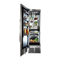
Column Refrigeration
Residental and Commercial
Brand: Perlick
|
Category: Refrigerator
|
Size: 12 MB
Table of Contents
Advertisement
Perlick CC24D Series Service Manual (133 pages)
Column Refrigeration
Brand: Perlick
|
Category: Refrigerator
|
Size: 14 MB
Table of Contents
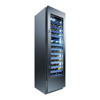
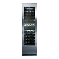
Perlick CC24D Series Installation & Operation Manual (28 pages)
Wine Column Refrigeration
Brand: Perlick
|
Category: Refrigerator
|
Size: 4 MB
Table of Contents
Advertisement
Advertisement