Sign In
Upload
Manuals
Brands
Omron Manuals
Amplifier
V700-L11
Omron V700-L11 ID Link Unit Manuals
Manuals and User Guides for Omron V700-L11 ID Link Unit. We have
7
Omron V700-L11 ID Link Unit manuals available for free PDF download: User Manual
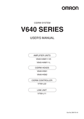
OMRON V700-L11 User Manual (144 pages)
V640 SERIES
Brand:
OMRON
| Category:
Amplifier
| Size: 3 MB
Table of Contents
Introduction
2
Performance Data
6
Ec Declaration of Conformity
9
Applicable SEMI Standards
10
Precautions for Safe Use
11
Precautions for Correct Use
12
Editor's Note
14
Table of Contents
15
Introduction
16
SECTION 1 Product Outline
18
What Is a CIDRW System
19
Features
20
System Configuration
21
Component Names and Functions
22
Cidrw Head V640-Hs
24
Flowchart for Getting Started
26
SECTION 2 Installation and Connections/Wiring
28
Installation
29
Influence of Background Metal on ID Tag
32
Influence of Noise
32
Connections and Wiring
34
Connector for Connecting a Cidrw Head
37
Power Supply
44
H
45
Host Connection Port
45
SECTION 3 Preparing for Communications
50
Set the Communications Conditions for the CIDRW Controller
51
Switch to the Setting Mode
51
100 C
56
Change the Data Segment Area
56
Change the Response Time-Out Time
59
Return to the Normal Operation Mode
61
Set the Communications Conditions for Amplifier Units
64
Set the Communications Conditions for Link Units
66
T
68
Communications Test
68
Test for Communications with the Host Device
68
W
69
When Secs Is Used
69
When Secs Is Not Used
71
SECTION 4 Reading From/Writing to ID Tags
72
When SECS Is Used
73
Message Specifications
73
Specifications for each Stream/Function
75
When SECS Is Not Used
84
Command/Response Format
84
S
89
Same Write
89
Noise Measurement
92
Troubleshooting
94
Setting Mode
99
A
101
Amplifier Unit Indicators
101
From Installation to Trial Operation
102
From Trial Operation to Communications
104
Specifications and Dimensions
107
Appendix
111
System Configuration Examples
111
Characteristic Data Depending on Conditions of Use
113
F
125
For Coaxial Installation
125
For Parallel Installation
126
For Face-To-Face Installation
126
500 D
132
Data Segment Area
132
Regular Inspection
133
Secs Protocol Specifications
134
Operation Model
134
Protocol Specifications
135
Support Attributes
137
Ascii Code Table
139
Protective Construction
140
Revision History
144
Advertisement
OMRON V700-L11 User Manual (141 pages)
V640 SERIES AMPLIFIER UNIT, CIDRW HEAD, CIDRW CONTROLLER, CIDRW CONTROLLER
Brand:
OMRON
| Category:
Amplifier
| Size: 3 MB
Table of Contents
Introduction
2
Performance Data
4
Applicable SEMI Standards
6
Applicable Standards
6
Precautions for Correct Use
7
Precautions for Safe Use
7
To Users of Model V700-L21
10
Editor's Note
11
Table of Contents
13
SECTION 1 Product Outline
15
What Is a CIDRW System
16
Features
17
System Configuration
18
Component Names and Functions
19
Amplifier Unit V640-Ham
20
Cidrw Head V640-Hs
21
Flowchart for Getting Started
23
SECTION 2 Installation and Connections/Wiring
25
Installation
26
Influence of Background Metal on ID Tag
29
Influence of Noise
29
Connections and Wiring
31
Connector for Connecting a Cidrw Head
34
Rs-232C Port
36
Rs-485 Port
39
Power Supply
41
Host Connection Port
42
SECTION 3 Preparing for Communications
47
Set the Communications Conditions for the CIDRW Controller
48
Change the Data Segment Area
53
Change the Response Time-Out Time
56
Return to the Normal Operation Mode
58
Set the Communications Conditions for Amplifier Units
61
Set the Communications Conditions for Link Units
63
Communications Test
65
When Secs Is Used
66
When SECS Is Used When SECS Is Not Used
69
SECTION 4 Reading From/Writing to ID Tags
69
Message Specifications
70
When SECS Is Not Used
81
Command/Response Format
81
Command Code List
83
Response Code List
83
Same Write
87
Noise Measurement
90
SECTION 5 Troubleshooting
91
When SECS Is Used
92
Troubleshooting
93
Setting Mode
96
Amplifier Unit Indicators
98
When SECS Is Not Used
98
From Installation to Trial Operation
99
From Trial Operation to Communications
101
SECTION 6 Appendix
103
Specifications and Dimensions
104
System Configuration Examples
108
Characteristic Data Depending on Conditions of Use
110
Mutual Interference Distances (Reference Only)
122
For Coaxial Installation
122
For Parallel Installation
123
For Face-To-Face Installation
123
Influence of Background Metals (Reference Only)
124
Data Segment Area
129
Regular Inspection
130
SECS Protocol Specifications
131
Operation Model
131
Protocol Specifications
132
Support Attributes
134
ASCII Code Table
136
Protective Construction
137
Iec (International Electrotechnical Commission)
137
Revision History
141
Omron V700-L11 User Manual (165 pages)
CIDRW SYSTEM, AMPLIFIER UNITS, CIDRW HEADS, CIDRW CONTROLLER, LINK UNIT
Brand:
Omron
| Category:
Amplifier
| Size: 6 MB
Table of Contents
Table of Contents
16
What Is a CIDRW System
18
Features
19
System Configuration
20
Component Names and Functions
21
Flowchart for Getting Started
26
Section 4 Reading From/Writing to ID Tags
75
When SECS Is Used
76
Get Attributes
78
Online Check
78
Set Attributes
79
Read Data
80
Write Data
81
Read ID
82
Write ID
82
Subsystem Command (Getstatus)
84
Subsystem Command (Performdiagnostics)
84
Subsystem Command (Reset)
85
When SECS Is Not Used
87
Byte Write
89
Clear Communications History
89
Get Communications History
89
Get Last Command
89
Get Parameter
89
Nak
89
Read
89
Same Write
89
Test
89
Write
89
When SECS Is Used
102
When SECS Is Not Used
108
SECTION 7 Appendix
115
Specifications and Dimensions
116
System Configuration Examples
121
Characteristic Data According to Conditions of Use
123
ID Tag Memory Maps
153
Regular Inspection
154
SECS Protocol Specifications
155
ASCII Code Table
160
Protective Construction
161
SECTION 8 Revision History
164
Advertisement
Omron V700-L11 User Manual (174 pages)
V640 Series CIDRW SYSTEM
Brand:
Omron
| Category:
Industrial Electrical
| Size: 9 MB
Table of Contents
Table of Contents
16
Flowchart for Getting Started
27
Refer to
32
Refer to
34
Refer to
35
Refer to
45
Setting the Communications Conditions for the CIDRW Controller
53
SECTION 6 Appendix
121
Specifications and Dimensions
122
System Configuration Examples
128
Characteristic Data According to Conditions of Use
131
ID Tag Memory Maps
161
Regular Inspection
162
SECS Protocol Specifications
163
ASCII Table
168
Protective Construction
169
Revision History
172
Omron V700-L11 User Manual (80 pages)
FOR SEMI STANDARD-COMPATIBLE CIDRW SYSTEM
Brand:
Omron
| Category:
Other
| Size: 1 MB
Table of Contents
Meanings of Signal Words
4
Meanings of Alert Symbols
4
Alert Statements in this Manual
4
Introduction
4
Precautions for Correct Use
5
Limitations about Model V700-HMD13
6
Table of Contents
7
Contents
7
Section 1 System Configuration and Features
9
System Configuration
10
Features
11
Section 2 Unit Specifications
13
CIDRW Controller: Model V700-L21
14
Names and Functions of Various Components/Specifications
14
Interface Specifications
17
Dimensional Drawing and Mounting Method
19
Names and Functions of Various Components/Specifications
20
Link Unit: Model V700-L11
20
Interface Specifications
23
Dimensional Drawing and Mounting Method
26
IDR/W Head: Model V700-HMD13
27
Names and Functions of Various Components/Specifications
27
Interface Specifications (same as with Model V700-HMD11-1)
28
Dimensional Drawing and Mounting Method
29
Communication Performance (Information Only)
31
IDR/W Head: Model V700-HMD11-1
32
Names and Functions of Various Components/Specifications
32
Interface Specifications (same as with Model V700-HMD13 )
33
Dimensional Drawing and Mounting Method
34
Communication Performance (Information Only)
35
ID Tag: Model V700-D23P41
36
Dimensional Drawing and Specifications
36
Memory Map
37
Section 3 System Connections
39
Connection Work and Startup
40
System Configuration Example
41
Section 4 SECS Protocol Specifications
43
Operation Model
44
Protocol Specifications
45
Support Attributes
47
Message Specifications
49
Operating Conditions
62
Section 5 Setup Mode
63
Accessing Setup Mode
64
How to Set up Parameters
65
Section 6 Reference
69
Processing Time (Information Only)
70
Performance Data Based on Operating Conditions (Information Only)
71
Effect of Nearby Metal Object Onto IDRW Head
71
Spacing for Installing IDRW Heads
72
Effect of Inclination of ID Tag
73
Section 7 Troubleshooting
75
No Acknowledge Message (Acknowledge Message Not yet Received)
76
Acknowledge Message Received (Other than SSACK="NO")
77
Revision History
79
Omron V700-L11 User Manual (63 pages)
FOR RFID SYSTEM FOR SEMI CONDUCTOR DEVICE FABRICATION LINE
Brand:
Omron
| Category:
Other
| Size: 1 MB
Table of Contents
Meanings of Signal Words
4
Meanings of Alert Symbols
4
Alert Statements in this Manual
4
Introduction
4
Precautions for Correct Use
5
Limitations about Model V700-HMD13
6
Table of Contents
7
Contents
7
Section 1 System Features and Configuration
9
System Features
10
System Configuration
11
Section 2 Unit Specifications
13
IDR/W Head: Model V700-HMD13
14
Names and Functions of Various Components/Specifications
14
Names and Functions of Various Components/ Specifications
14
Interface Specifications (same as with Model V700-HMD11-1)
15
Dimensional Drawing and Mounting Method
17
Communication Performance (Information Only)
19
IDR/W Head: Model V700-HMD11-1
20
Names and Functions of Various Components/Specifications
20
Names and Functions of Various Components/ Specifications
20
Interface Specifications (same as with Model V700-HMD13 )
21
Specifications
21
Dimensional Drawing and Mounting Method
23
Communication Performance (Information Only)
24
ID Link Unit: Model V700-L11
25
Names and Functions of Various Components/Specifications
25
Interface Specifications
28
Dimensional Drawing and Mounting Method
32
ID Tag: Model V700-D23P41-1
33
Section 3 System Configuration Examples
35
Configuration Based on Upstream Controller and RS-232C
36
Configuration Based on Upstream Controller and RS-485
37
Section 4 Data Read/Write with ID Tag
39
Operating Principle
40
Command/Response Frame Structure
41
Response Code List
43
Command Types and Response <Applicable to OMRON Original 1:1 Protocol
44
Read
44
Write
45
Same Write
46
Byte Write
47
Test
48
Section 5 Data Transaction Time (Information Only)
49
Data Transaction Time
50
TAT (Turn Around Time)
51
Section 6 Performance Data Based on Operating Conditions (Information Only)
53
Effect of Nearby Metal Object Onto IDRW Head
54
Spacing for Installing IDRW Heads
55
Effect of Inclination of ID Tag
56
Section 7 Troubleshooting
57
IDRW Head Is Directly Connected to Upstream Controller
58
No Response (Response Not yet Received), Or, Occurrence of Illegal Characters
58
Response Is Available (Response Code Is Other than "00")
58
Configuration Using Link Unit
59
No Response (Response Not yet Received), or Occurrence of Illegal Characters
59
Response Is Available (Response Code Is Other than "00")
60
Memory Assignment with SEMI E99-Conforming System (with Model V700-L21)
61
Revision History
62
Omron V700-L11 User Manual (64 pages)
CIDRW SYSTEM
Brand:
Omron
| Category:
Amplifier
| Size: 3 MB
Table of Contents
Introduction
3
Table of Contents
4
General Safety Precautions
6
Warning
6
Caution
6
Notice
7
Applicable SEMI Standards
9
Applicable Standards
10
Editor's Note
12
SECTION 1 Product Outline
13
What Is a CIDRW System
14
Features
15
System Configuration
16
Component Names and Functions
17
Flowchart for Getting Started
21
SECTION 2 Installation and Connections/Wiring
23
Installation
24
Connections and Wiring
29
SECTION 3 Preparing for Communications
45
Set the Communications Conditions for the CIDRW Controller
46
Set the Communications Conditions for Amplifier Units
57
Set the Communications Conditions for Link Units
59
Communications Test
61
When SECS Is Used
61
When SECS Is Not Used
61
Advertisement
Related Products
Omron V700-L22
Omron V1000 Series
Omron V1000 VZA B0P2B
Omron V1000 VZA 20P4B
Omron V1000 VZA 2015F
Omron V1000 VZA 41P5B
Omron V1000 VZA 44P0B
Omron V640-HAM11-ETN-V2
Omron V640-HAM11-V3
Omron V640-HAM11-L
Omron Categories
Blood Pressure Monitor
Controller
Accessories
Switch
Inverter
More Omron Manuals
Login
Sign In
OR
Sign in with Facebook
Sign in with Google
Upload manual
Upload from disk
Upload from URL