Table of Contents
Advertisement
Quick Links
Advertisement
Table of Contents

Related Manuals for Omron V700-HMD13 series


Summary of Contents for Omron V700-HMD13 series
- Page 1 RFID SYSTEM FOR SEMI CONDUCTOR DEVICE FABRICATION LINE USER'S MANUAL ID Link Unit Model V700-L11 IDRW Head Model V700-HMD13 Model V700-HMD11-1 ID Tag Model V700-D23P41-1 OMRON Corporation © OMRON Corporation 2003 All Right Reserved Catalog No. Z213-E1-01B...
- Page 2 Introduction Thank you for purchasing the OMRON product. To be able to operate the product safely and efficiently, carefully study this user's manual and get fully familiar with the instruction in it before attempting to use the product. Keep this manual at hand for speedy reference...
- Page 3 Please read and understand this document before using the products. Please consult your OMRON representative if you have any questions or comments. WARRANTY OMRON’s exclusive warranty is that the products are free from defects in materials and workmanship for a period of one year (or other period if specified) from date of sale by OMRON. OMRON...
-
Page 4: Introduction
Introduction Meanings of Signal Words The following signal words are used in this manual. Indicates a potentially hazardous situation which, if not avoided, will result in minor or moderate injury, or may result in serious injury or death. Additionally, there may be WARNING significant property damage. -
Page 5: Precautions For Correct Use
Introduction Precautions for Correct Use To operate the system more reliably and to allow the system to fully perform as designed, follow the instructions below: About environments of installation Do not install or leave the product to a location such as: •... -
Page 6: Limitations About Model V700-Hmd13
Introduction Limitations about Model V700-HMD13 When a Model V700-HMD13 (not Model V700-HMD13 ) is used to configure a system, there will be the operating limitations described below. <Description of limitations> Among the memory page1 1 through 30 on an ID tag, page 1 through 12 are available to the user. Do not access to page 13 to 30 with commands. -
Page 7: Table Of Contents
Introduction CONTENTS Introduction Meanings of Signal Words Meanings of Alert Symbols Alert statements in this Manual Precautions for Correct Use Limitations about Model V700-HMD13 CONTENTS Section 1 System Features and Configuration 1.1 System features 1.2 System configuration Section 2 Unit Specifications 2.1 IDR/W head: Model V700-HMD13 2.1.1 Names and functions of various components/specifications 2.1.2 Interface specifications (same as with Model V700-HMD11-1) - Page 8 Introduction Section 4 Data Read/Write with ID Tag 4.1 Operating principle 4.2 Command/response frame structure 4.3 Response code list 4.4 Command types and response <applicable to OMRON original 1:1 protocol> 4.4.1 Read 4.4.2 Write 4.4.3 Same write 4.4.4 Byte write 4.4.5 Test...
-
Page 9: Section 1 System Features And Configuration
Section 1 System Features and Configuration 1.1 System features 1.2 System configuration V700-L11 User's Manual... -
Page 10: System Features
System Features and Configuration 1.1 System features OMRON's RFID system for semiconductor device fabrication line is configured with the following units: Model V700-HMD13 , or V700-HMD11-1 (ID R/W head) An ID R/W head that reads or writes data from or into the memory on ID tag without a need to contact the ID tag. -
Page 11: System Configuration
Section 1 System Features and Configuration 1.2 System configuration By combining an IDRW head and a link unit, various system configurations (connection configuration, supply voltage). Interfacing with upstream controller: RS-232C Unit-to-unit configuration IDRW head/link unit connection configuration • 1:1 connection (RS-232C) ID tag •... - Page 12 Section 1 System Features and Configuration By altering the connection to a link unit, it is possible to connect the link unit to an upstream controller that has RS-485 interface. Interfacing with upstream controller: RS-485 Unit-to-unit configuration IDRW head/link unit connection configuration •...
-
Page 13: Section 2 Unit Specifications
Section 2 Unit Specifications 2.1 IDR/W head: Model V700-HMD13 2.1.1 Names and functions of various components/ specifications 2.1.2 Interface specifications (same as with Model V700-HMD11-1) 2.1.3 Dimensional drawing and mounting method 15 2.1.4 Communication performance (information only) 17 2.2 IDR/W head: Model V700-HMD11-1 2.2.1 Names and functions of various components/ specifications 2.2.2 Interface specifications (same as with Model... -
Page 14: Idr/W Head: Model V700-Hmd13
Section 2 Unit Specifications 2.1 IDR/W head: Model V700-HMD13 2.1.1 Names and functions of various components/specifications Communication area Mounting bracket I/F connector I/F cable Antenna section Antenna section This section reads or writes data from or into an ID tag. Mounting bracket This bracket is for securing the antenna section. -
Page 15: Interface Specifications (Same As With Model V700-Hmd11-1)
9-pin D-SUB connector plug, with M2.6 lock screws Power supply 5 VDC±5% Communication standard RS-232C Synchronization Asynchronous mode, start-stop synchronization Communications control stan- OMRON original 1:1 protocol dard Baud rate (fixed) 9600 bps Character format (fixed) Start bit Data bit Parity bit... - Page 16 XM2Z-0001 (OMRON) : <DOS/V PC side> socket-Model XM2D-0901 (OMRON), hood-Model XM2S-0911(OMRON) • Recommended 5 V power supply : <for AC input> Model S82S-0705 (OMRON), <for DC input> Model S82S-7705 (OMRON) <Connection with link unit> The IDR/W head can be directly connected to the ID connection port on the link unit. When consider- ing extending the cable, use the cable whose configuration is specified below.
-
Page 17: Dimensional Drawing And Mounting Method
Section 2 Unit Specifications 2.1.3 Dimensional drawing and mounting method IDR/W head with mounting brackets installed PVC-insulated round cable 6 (7/ 0.18) 8-core, Coil 4-M4 standard length, 1 m (FOUP side) 119.8 149.8 Mounting bracket (material: SUS 304) Mounting bracket (material: SUS 304) 4-M4 22.4... - Page 18 Section 2 Unit Specifications Mounting brackets 2-M4 2-M4 10.1 10.1 44.8 44.8 36.4 36.4 Mounting hole drawing Mounting holes dimensions Mounting holes dimensions (front mounting configuration) (top mounting configuration) 4-M4 or ∗ Be sure to limit the tightening torque for the M4 screws and bracket mounting screws to 1.2 N-m or less. In the installation work, do not exert an excessively strong force to the case or deform the case.
-
Page 19: Communication Performance (Information Only)
Section 2 Unit Specifications 2.1.4 Communication performance (information only) Communication area (Model V700-HMD13 vs. Mode V700-D23P41-1) Locus of the tip of V700-D23P41-1 V700-D23P41 FOUP side Unit: mm Location of the tip of ID tag Antenna Range supported by the HMD13A and D23P41-1. -
Page 20: Idr/W Head: Model V700-Hmd11-1
Section 2 Unit Specifications 2.2 IDR/W head: Model V700-HMD11-1 2.2.1 Names and functions of various components/specifications Communication area I/F connector I/F cable Antenna section Status indicators (located on sideplate) Antenna section This section reads or writes data from or into an ID tag. I/F connector This interface connector supplies power to IDR/W head, and permits data transmission with an upstream controller. -
Page 21: Interface Specifications (Same As With Model V700-Hmd13 )
9-pin D-SUB connector plug, with M2.6 lock screws ± Power supply 5 VDC Communication standard RS-232C Synchronization Asynchronous mode, start-stop synchronization Communications control stan- OMRON original 1:1 protocol dard Baud rate (fixed) 9,600 bps Character format (fixed) Start bit Data bit Parity bit Stop bit... - Page 22 XM2Z-0001 (OMRON) : <DOS/V PC side> socket-Model XM2D-0901 (OMRON), hood-Model XM2S-0911(OMRON) • Recommended 5 V power supply : <for AC input> Model S82S-0705 (OMRON), <for DC input> Model S82S-7705 (OMRON) <Connection with link unit> The IDR/W head can be directly connected to the ID connection port on the link unit. When consider- ing extending the cable, use the cable whose configuration is specified below.
-
Page 23: Dimensional Drawing And Mounting Method
Section 2 Unit Specifications 2.2.3 Dimensional drawing and mounting method Model V700-HMD11-1 6, length 1000 Lock screw 2- 10 4-R1 (mounting hole) 45.5 Status indicator Case material ABS resin Filler resin Epoxy resin Cable PVC (oil-resistant) (Unit: mm) Mounting method (1) Front mounting 2-M4 Center of coil... -
Page 24: Communication Performance (Information Only)
Section 2 Unit Specifications 2.2.4 Communication performance (information only) Communication area (Model V700-HMD11-1 vs. Mode V700-D23P41) Recommended communication area Y(mm) 37mm Model V700-HMD11-1 X(mm) Effect of background metal (Model V700-HMD11-1 vs. Mode V700-D23P41) Model V700-HMD11-1 Distance to background metal X (mm) V700-L11 User's Manual... -
Page 25: Id Link Unit: Model V700-L11
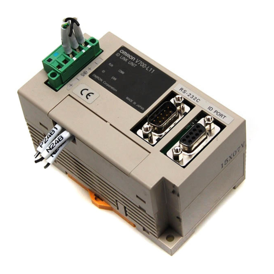
Section 2 Unit Specifications 2.3 ID link unit: Model V700-L11 2.3.1 Names and functions of various components/specifications Multiconnection port (RS-485) Status indicators Upstream controller connection port (RS-232C) ID connection port RUN COMM ID ERR Setup DIP-SW (behind cover) 24 V power terminals (behind cover) Upstream controller connection port (RS-232C) This port is for connection to the CIDRW controller according to RS-232C interface standard, and a dust cover has been factory-installed to it. - Page 26 RS-485 terminator ON/ OFF • Recommended 24 V power supply: Model S82K-03024 (OMRON) • Set the RS-485 terminator setting to ON for the link units on both ends of multidrop, and to OFF for other units. If only one link unit is operated, set the terminator setting to ON.
- Page 27 Section 2 Unit Specifications • Assign a unique node No. to an IDRW head within a given subsystem. [DIP-SW setting vs. Node No. correspondence table] Switch No. in setup DIP-SW Node No. Prohibited V700-L11 User's Manual...
-
Page 28: Interface Specifications
Connector specification 9-pin D-SUB connector plug, with #4-40UNC lock screws Communication standard RS-232C Synchronization Asynchronous mode, start-stop synchronization Communications control OMRON original 1:N protocol standard Baud rate 38400, 19200, 9600, 4800 bps (selectable with DIP-SW) Character format Start bit Data bit... - Page 29 ∗2 If CS function is used on the DOS/V PC side, a loop-back line is necessary. • Recommended cable: CO-MA-VV-SB 5PX28AWG (Hitachi Cable, Ltd.) • Recommended connector: socket-Model XM2D-0901 (OMRON), hood-Model XM2S-0913 (OMRON) Wrong wiring connection can lead to a malfunction of the equipment. Be fully sure of the correct wiring connections.
- Page 30 Connector Special 5-pin connector (included in link unit) Communication standard RS-485 Synchronization Asynchronous mode, start-stop synchronization Communications control OMRON original 1:N protocol standard Baud rate 38400, 19200, 9600, 4800 bps (selectable with DIP-SW) Character format Start bit Data bit Parity bit...
- Page 31 An ordinary screwdriver whose shank is tapered at the tip does not go all the way into the hole. Use a miniature flat-blade screwdriver with a straight shank. Tighten the cable locking screws at an appropriated tightening torque (approx. 0.5 N-m). The following purpose-built screwdriver is available: OMRON: Model XW4Z-00C Form of tip Side view Front view...
-
Page 32: Dimensional Drawing And Mounting Method
Section 2 Unit Specifications 2.3.3 Dimensional drawing and mounting method 41.5 RS-232C connector 26.5 41.3 18.5 20.3 ID port connector 4 Status indicators RS-485 connector Mounting holes 2-M4 or Case material PC/ABS resin (Unit: mm) ∗ Be sure to limit the tightening torque for the M4 screws to 1.2 N-m or less. ∗... -
Page 33: Id Tag: Model V700-D23P41-1
Section 2 Unit Specifications 2.4 ID tag: Model V700-D23P41-1 General specifications Characteristic Specification Memory capacity 240 bytes (user area) Memory type EEP-ROM Data retention time 10 years after data writing Number of overwrites 100,000 times per address −25 to +70°C (no freezing) Operating ambient temperature −40 to +110°C (no freezing) Operating ambient temperature... - Page 34 Section 2 Unit Specifications MEMO V700-L11 User's Manual...
-
Page 35: Section 3 System Configuration Examples
Section 3 System Configuration Examples 3.1 Configuration based on upstream controller and RS-232C 34 3.2 Configuration based on upstream controller and RS-485 V700-L11 User's Manual... -
Page 36: Configuration Based On Upstream Controller And Rs-232C
Section 3 System Configuration Examples 3.1 Configuration based on upstream controller and RS-232C 24 V 24 V 24 V 24 V power power power power supply supply supply supply Upstream 24V- 24V- 24V- 24V- controller 54321 54321 54321 54321 24V+ 24V+ 24V+ 24V+... -
Page 37: Configuration Based On Upstream Controller And Rs-485
Section 3 System Configuration Examples 3.2 Configuration based on upstream controller and RS-485 24 V 24 V 24 V 24 V power power power power supply supply supply supply 24V- 24V- 24V- 24V- 54321 54321 54321 54321 Upstream controller 24V+ 24V+ 24V+ 24V+... - Page 38 Section 3 System Configuration Examples MEMO V700-L11 User's Manual...
-
Page 39: Section 4 Data Read/Write With Id Tag
Section 4 Data Read/Write with ID Tag 4.1 Operating principle 4.2 Command/response frame structure 4.3 Response code list 4.4 Command types and response <applicable to OMRON original 1:1 protocol> 4.4.1 Read 4.4.2 Write 4.4.3 Same write 4.4.4 Byte write 4.4.5 Test... -
Page 40: Operating Principle
Section 4 Data Read/Write with ID Tag 4.1 Operating principle A memory space of 240 bytes is assigned to an ID tag user. With this memory space, an 8-byte area (such as 00h-07h, 08h-0Fh ) is handled as one page. The IDRW head can interact with the ID tag memory as described below. -
Page 41: Command/Response Frame Structure
Section 4 Data Read/Write with ID Tag 4.2 Command/response frame structure Direct connection to IDRW head-OMRON original 1:1 protocol Command frame structure Command code Parameter 1 Parameter n ∗ Arrange data transmission so that an inter-character spacing is less than 2 seconds. A spacing in excess of 2 seconds will trigger a command error. - Page 42 Data Read/Write with ID Tag Configuration involving link unit-OMRON original 1:N protocol When intending to operate a link unit, OMRON original 1:1 protocol format is prefixed with [SOH] and Node No. and suffixed with a check code. Command frame structure SOH Node No.
-
Page 43: Response Code List
Section 4 Data Read/Write with ID Tag 4.3 Response code list Response Type Name Description code Normal comple- Normal completion • No error occurred and command execution completed normally. tion Error in communi- Parity error • A parity error has occurred with any character in the command. cation to IDRWH Framing error •... -
Page 44: Command Types And Response
Data Read/Write with ID Tag 4.4 Command types and response <applicable to OMRON original 1:1 protocol> 4.4.1 Read This command is used to read data from an ID tag. It is possible to read data of arbitrary pages on a page by page basis. -
Page 45: Write
Section 4 Data Read/Write with ID Tag 4.4.2 Write This command is used to write data into an ID tag page by page. It is possible to write data into arbitrary pages. At a time, data can be written into up to 16 pages. Command frame structure As parameters associated to this command, a data write page(s) and data being written into each page are transmitted. -
Page 46: Same Write
Section 4 Data Read/Write with ID Tag 4.4.3 Same write This command is used to write a same data set into an ID tag page by page. It is possible to write a data set into arbitrary pages. Command frame structure As parameters associated to this command, a data write page and data (identical to each page) for respective pages are transmitted. -
Page 47: Byte Write
Section 4 Data Read/Write with ID Tag 4.4.4 Byte write This command is used to write a block of data of a given number of bytes (up to 128 bytes) in an area beginning with a specified address in an ID tag. It is possible to define an area that spans a plurality of pages. At a time, data can be written into up to 16 pages. -
Page 48: Test
Section 4 Data Read/Write with ID Tag 4.4.5 Test This command is for verifying loop back communications performance between the upstream controller and IDRW head. Upon receiving this command, the IDRW head returns the response code and test data of command as a response to the upstream controller. -
Page 49: Section 5 Data Transaction Time (Information Only)
Section 5 Data Transaction Time (information only) 5.1 Data transaction time 5.2 TAT (Turn Around Time) V700-L11 User's Manual... -
Page 50: Data Transaction Time
Section 5 Data Transaction Time (information only) The communication time with this RFID system can be categorized into two types-data transaction time and TAT (Turn Around Time). 5.1 Data transaction time This is a time span needed for data transaction between the IDRW head and ID tag, and will vary depending on the number of pages subjected to data reading or writing. -
Page 51: Tat (Turn Around Time)
This is a time span needed for the upstream controller to send a command and receive a response, and is governed by the transaction time and number of characters of command/response. IDRW head is directly connected-OMRON original 1:1 protocol Command... - Page 52 Section 5 Data Transaction Time (information only) IDRW head is connected via link unit-OMRON original 1:N protocol Processing time on link unit Command Response transmission time transmission time Upstream 1.6 msec 1.6m sec controller Command Response Link unit Command Response...
-
Page 53: Section 6 Performance Data Based On Operating Conditions (Information Only)
Section 6 Performance Data Based on Operating Conditions (information only) 6.1 Effect of nearby metal object onto IDRW head 6.2 Spacing for installing IDRW heads 6.3 Effect of inclination of ID tag V700-L11 User's Manual... -
Page 54: Effect Of Nearby Metal Object Onto Idrw Head
Section 6 Performance Data Based on Operating Conditions (information only) The maximum effective communication distance of an IDRW head varies depending on the operating conditions (presence/absence of a nearby metal object, number of the IDRW heads, etc.). This section describes the effect of varying operating conditions on the effective communication distance. Before operating the IDRW heads, study the information in this section. -
Page 55: Spacing For Installing Idrw Heads
Section 6 Performance Data Based on Operating Conditions (information only) 6.2 Spacing for installing IDRW heads When two or more IDRW heads are connected via link unit, there is no limitation on the spacing of antenna sections since all the IDRW heads do not handle a command simultaneously. If IDRW heads are connected to an individual upstream controller, and when these IDRW heads situated in close vicinity are simultaneously processing a command, mutual interference can occur across the IDRW heads, possibly leading to total inability of communication or loss in effective communication distance despite... -
Page 56: Effect Of Inclination Of Id Tag
Section 6 Performance Data Based on Operating Conditions (information only) 6.3 Effect of inclination of ID tag Mount the IDRW head and ID tag as vertical as possible. The IDRW head or ID tag remains capable of communication even if installed inclined. However, in this situation, a shorter communication distance will result. -
Page 57: Section 7 Troubleshooting
Section 7 Troubleshooting 7.1 IDRW head is directly connected to upstream controller 7.1.1 No response (response not yet received), or, occurrence of illegal characters 7.1.2 Response is available (response code is other than "00") 7.2 Configuration using link unit 7.2.1 No response (response not yet received), or occurrence of illegal characters 7.2.2 Response is available (response... -
Page 58: Idrw Head Is Directly Connected To Upstream Controller
Section 7 Troubleshooting If a fault should occur, first thoroughly study the symptom in order to be able to correctly judge the reproducibility of a problem, and interaction with other associated equipment. Thus, find an appropriate remedy. 7.1 IDRW head is directly connected to upstream controller 7.1.1 No response (response not yet received), or, occurrence of ille- gal characters... -
Page 59: Configuration Using Link Unit
Section 7 Troubleshooting 7.2 Configuration using link unit 7.2.1 No response (response not yet received), or occurrence of ille- gal characters In normal communication status, the STATUS indicators will appear as follows: COMM Normally lit Lit during communication service Lit during communication with IDRW Normally unlit Check the following points based on the states of STATUS indicators on a link unit that has failed to communicate. -
Page 60: Response Is Available (Response Code Is Other Than "00")
Section 7 Troubleshooting 7.2.2 Response is available (response code is other than "00") According to the response code in response data, check the following points. Error in communication with upstream controller side Response code Name Typical checkpoint "14" Format error •... -
Page 61: Memory Assignment With Semi E99-Conforming System (With Model V700-L21)
[Reference] <Memory assignment with SEMI E99-conforming system (with Model V700-L21)> Memory map in ID tag (00h through EFh correspond with addresses) Page 8 bytes/page Carrier ID (16 bytes) "S01" "S02" "S03" "S04" "S05" "S06" "S07" "S08" "S09" "S10" "S11" "S12" "S13"... -
Page 62: Revision History
Revision History A manual revision code is suffixed to the manual ID located to the bottom right corner of front cover and to the bottom left corner of back cover. Catalog No. Z213-E1-01B Revision code Revision note Date Revised contents August 2000 version Warranty and liability information added to beginning of manual,... - Page 63 OMRON ASIA PACIFIC PTE. LTD. 83 Clemenceau Avenue, #11-01, UE Square, 239920 Singapore Tel: (65)6835-3011/Fax: (65)6835-2711 OMRON CHINA CO., LTD. BEIJING OFFICE Room 1028, Office Building, Beijing Capital Times Square, No. 88 West Chang'an Road, Beijing, 100031 China Tel: (86)10-8391-3005/Fax: (86)10-8391-3688 Cat.