Omron TM14M Collaborative Robot Manuals
Manuals and User Guides for Omron TM14M Collaborative Robot. We have 7 Omron TM14M Collaborative Robot manuals available for free PDF download: Hardware Installation Manual, Quick Start Manual
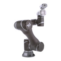
Omron TM14M Hardware Installation Manual (79 pages)
Table of Contents
-
-
-
Overview18
-
-
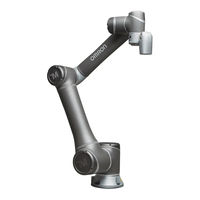
Robot Arm19
-
Tm5X-70037
-
Control Box39
-
Robot Stick40
-
-
-
Overview46
-
Control Box46
-
-
Analog in56
-
Analog out57
-
USB Port58
-
-
-
-
Advertisement
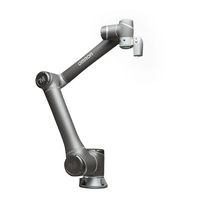
Omron TM14M Hardware Installation Manual (82 pages)
Medium & Heavy Payload Series
Table of Contents
-
Overview11
-
Labels15
-
Overview18
-
Robot Arm19
-
Control Box39
-
Robot Stick40
-
Overview47
-
Control Box47
-
Analog in57
-
Analog out58
-
USB Port59
-
Overview69
-
Unboxing70
-
Carton Types70
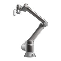
Omron TM14M Hardware Installation Manual (82 pages)
Medium & Heavy Payload
Table of Contents
-
Overview11
-
Labels15
-
Overview18
-
Robot Arm19
-
Control Box39
-
Robot Stick40
-
Overview47
-
Control Box47
-
Analog in57
-
Analog out58
-
USB Port59
-
Overview69
-
Unboxing70
-
Carton Types70
Advertisement
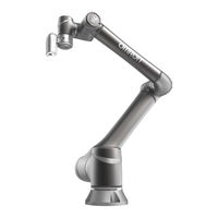
Omron TM14M Hardware Installation Manual (80 pages)
Table of Contents
-
Overview11
-
Labels15
-
Overview18
-
Robot Arm19
-
Control Box39
-
Robot Stick40
-
Overview46
-
Control Box46
-
Analog in56
-
Analog out57
-
USB Port58
-
Overview68
-
Unboxing69
-
Carton Types69
Omron TM14M Hardware Installation Manual (80 pages)
Medium & Heavy Payload
Table of Contents
-
Overview11
-
Labels15
-
Overview18
-
Robot Arm19
-
Control Box39
-
Robot Stick40
-
Overview46
-
Control Box46
-
Analog in56
-
Analog out57
-
USB Port58
-
Overview68
-
Unboxing69
-
Carton Types69
Omron TM14M Hardware Installation Manual (68 pages)
Collaborative Robot
Table of Contents
-
-
Overview16
-
-
Robot Arm17
-
Control Box32
-
Robot Stick32
-
-
-
-
-
Overview36
-
Control Box37
-
-

Omron TM14M Quick Start Manual (12 pages)
Collaborative Robot. Safety Laser Scanner Installation.
Table of Contents
Advertisement