Sign In
Upload
Manuals
Brands
Omron Manuals
Processor
CP1L-M30D Series
Omron CP1L-M30D Series Manuals
Manuals and User Guides for Omron CP1L-M30D Series. We have
7
Omron CP1L-M30D Series manuals available for free PDF download: Programming Manual, Operation Manual, Introduction Manual, Getting Started Manual, Brochure
OMRON CP1L-M30D Series Programming Manual (1175 pages)
CP1H/CP1L CPU Unit
Brand:
OMRON
| Category:
Processor
| Size: 13.98 MB
Table of Contents
Table of Contents
12
About this Manual
14
Related Manuals
16
Precautions
22
General Precautions
23
Intended Audience
23
Safety Precautions
23
Operating Environment Precautions
25
Application Precautions
26
Applicable Directives
29
Concepts
29
Conformance to EC Directives
29
Relay Output Noise Reduction Methods
30
Conditions for Meeting EMC Directives When Using CP1, CP-Series, or CPM1A Relay Expansion I/O Units
31
Section 1 Programming Concepts
34
Programming Concepts
34
Programming Concepts
35
Programs and Tasks
35
Basic Information on Instructions
37
Instruction Location and Execution Conditions
39
Addressing I/O Memory Areas
40
Specifying Instruction Operands
41
Data Formats
46
Execution Conditions
50
Instruction Variations
50
I/O Instruction Timing
52
1-1-10 Refresh Timing
53
1-1-11 Program Capacity
55
1-1-12 Basic Ladder Programming Concepts
55
1-1-13 Inputting Mnemonics
60
1-1-14 Program Examples
61
Condition Flags
66
Precautions
66
Special Program Sections
71
Checking Programs
74
CX-Programmer
74
Program Checks with the CX-Programmer
75
Program Execution Check
76
Other Errors
77
Checking Fatal Errors
78
Introducing Function Blocks
79
Overview and Features
79
Function Block Specifications
80
Files Created with CX-Programmer
81
Section 2 Tasks
82
Overview
83
Programming with Tasks
83
Tasks and Programs
85
Basic CPU Unit Operation
86
Types of Tasks
87
Cyclic Task Status
89
Task Execution Conditions and Settings
89
Status Transitions
90
TASK on and TASK off
91
Using Tasks
91
Task Instruction Limitations
94
Flags Related to Tasks
95
Examples of Tasks
98
Designing Tasks
99
Global Subroutine
101
Interrupt Tasks
101
Types of Interrupt Tasks
101
External Interrupt
105
Interrupt Task Flags and Words
106
Application Precautions
107
CX-Programmer Operations for Tasks
108
Instructions
110
Notation and Layout of Instruction Descriptions
119
Sequence Input Instructions
122
Load: Ld
122
Load Not: Ld Not
124
And: and
126
And Not: and Not
128
Or: or
130
Or Not: or Not
131
And Load: and Ld
133
Or Load: or Ld
135
Differentiated and Immediate Refreshing Instructions
138
Operation Timing for I/O Instructions
139
Tr Bits
140
Sequence Output Instructions
146
Output: out
146
Output Not: out Not
147
Set and Reset: Set and Rset
155
Sequence Control Instructions
165
Overview of Interlock Instructions
166
Timer and Counter Instructions
201
Timer Operation
202
Comparison Instructions
242
Data Movement Instructions
280
Data Shift Instructions
307
Specified Values Only
342
Increment/Decrement Instructions
353
Symbol Math Instructions
369
Conversion Instructions
422
Logic Instructions
469
Special Math Instructions
484
Floating-Point Math Instructions
505
Double-Precision Floating-Point Instructions
558
Table Data Processing Instructions
600
Data Control Instructions
648
Subroutines
701
Interrupt Control Instructions
725
0000 Hex: Recorded Interrupt Retained
732
0001 Hex: Recorded Interrupt Cleared
732
S Recorded Interrupt Clear Specification
732
Section 3-19
733
High-Speed Counter/Pulse Output Instructions
738
Auxiliary Bit Area
739
CIO 0 to CIO
739
CIO Area
739
Counter Area
739
Holding Bit Area
739
Operand Specifications
739
Timer Area
739
Work Area
739
C0000 to C4095
749
D0 to D32767 @ D0 to @ D32767
749
T0000 to T4095
749
DR0 to DR15, IR0 to IR15
754
IR0 to ,IR15
754
To +2047, IR0 to -2048 to +2047, IR15
754
Step Instructions
784
IR0+(++) to ,IR15+(++) ,-(- -)IR0 To, -(- -)IR15
786
Application Examples
796
Basic I/O Unit Instructions
802
Serial Communications Instructions
838
Advertisement
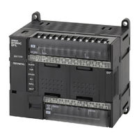
OMRON CP1L-M30D Series Operation Manual (810 pages)
CP1L CPU Unit
Brand:
OMRON
| Category:
Computer Hardware
| Size: 16.89 MB
Table of Contents
Table of Contents
12
About this Manual
15
Related Manuals
17
Precautions
23
General Precautions
24
Intended Audience
24
Safety Precautions
24
Operating Environment Precautions
26
Application Precautions
27
Conformance to EC Directives
30
Applicable Directives
30
Relay Output Noise Reduction Methods
30
Conformance to EC Directives
32
Conditions for Meeting EMC Directives When Using CP/CPM1A Relay Expansion I/O Units
32
Section 1 Features and System Configuration
35
Features and System Configuration
35
Features and Main Functions
36
CP1L Overview
36
Features and Main Functions
38
Features
41
System Configuration
49
Basic System
49
Optional Products
50
Serial Communications
50
System Expansion
52
Restrictions on System Configuration
55
Connecting the CX-Programmer
57
Connecting with a Commercially Available USB Cable
58
Connecting to a Serial Port
65
Function Charts
67
Function Blocks
68
Overview of Function Blocks
68
Advantages of Function Blocks
68
Section 2 Nomenclature and Specifications
71
Nomenclature and Specifications
71
Part Names and Functions
72
CP1L CPU Units
72
CP1W-CIF01 RS-232C Option Boards
75
CP1W-CIF11/CIF12 RS-422A/485 Option Boards
76
Specifications
77
CP1L CPU Units
77
Current Consumption
80
I/O Memory Details
84
I/O Specifications
85
Input Specifications
98
Output Specifications
100
CP/CPM1A-Series Expansion I/O Unit I/O Specifications
103
CP1L CPU Unit Operation
107
Overview of CPU Unit Configuration
107
Flash Memory Data Transfers
111
Memory Cassette Data Transfers
113
CPU Unit Operation
115
General Flow
115
I/O Refresh Methods
116
I/O Refreshing and Peripheral Servicing
116
Initialization at Startup
118
CPU Unit Operating Modes
119
Operating Modes
119
Status and Operations in each Operating Mode
119
Operating Mode Changes and I/O Memory
120
Startup Mode Setting
120
Power off Operation
121
Overview
121
Description of Operation
122
Instruction Execution for Power Interruptions
122
Computing the Cycle Time
123
CPU Unit Operation Flowchart
123
Cycle Time Overview
124
Functions Related to the Cycle Time
125
Minimum Cycle Time
125
Cycle Time Calculation Example
127
I/O Refresh Times for PLC Units
127
Online Editing Cycle Time Extension
128
I/O Response Time
129
Interrupt Response Times
130
Serial PLC Link Response Performance
131
2-7-10 Pulse Output Start Time
132
2-7-11 Pulse Output Change Response Time
132
Section 3 Installation and Wiring
133
Fail-Safe Circuits
134
Installation Precautions
135
Installation and Wiring Precautions
135
Mounting
137
Mounting in a Panel
137
Connecting Expansion Units and Expansion I/O Units
140
Mounting Height
140
DIN Track Installation
142
Wiring CP1L CPU Units
144
Wiring Power Supply and Ground Lines
145
Wiring Built-In I/O
147
Wiring Safety and Noise Controls
150
Wiring CPU Unit I/O
152
I/O Wiring for CPU Units with 60 I/O Points
152
I/O Wiring for CPU Units with 40 I/O Points
153
I/O Wiring for CPU Units with 30 I/O Points
155
I/O Wiring for CPU Units with 20 I/O Points
156
I/O Wiring for CPU Units with 14 I/O Points
158
I/O Wiring for CPU Units with 10 I/O Points
159
Pulse Input Connection Examples
161
Pulse Output Connection Examples
161
CP/CPM1A-Series Expansion I/O Unit Wiring
164
Section 4 I\/O Memory Allocation
171
I/O Memory Allocation
171
Overview of I/O Memory Area
172
I/O Memory Area
172
Overview of the Data Areas
173
Clearing and Holding I/O Memory
177
Hot Start/Hot Stop Functions
177
I/O Area and I/O Allocations
179
I/O Bits Allocated to CPU Units
180
I/O Bits Allocated to Expansion I/O Units
182
I/O Allocation Examples with Expansion I/O Units
184
I/O Word Allocations to Expansion Units
185
1:1 Link Area
186
Serial PLC Link Area
187
Internal Work Area
187
Holding Area (H)
188
Auxiliary Area (A)
189
TR (Temporary Relay) Area
189
Timers and Counters
190
Timer Area (T)
190
Counter Area (C)
191
Changing the BCD or Binary Mode for Counters and Timers
193
Data Memory Area (D)
194
4-11 Index Registers
195
4-11-1 Using Index Registers
199
4-11-2 Precautions for Using Index Registers
201
4-12 Data Registers
203
4-13 Task Flags
205
4-14 Condition Flags
205
4-15 Clock Pulses
207
Section 5 Pulse and Counter Functions
209
Pulse and Counter Functions
209
High-Speed Counters
210
Overview
210
High-Speed Counter Specifications
211
Procedure
216
PLC Setup
217
High-Speed Counter Terminal Allocation
218
Ladder Program Example
224
Pulse Input Connection Examples
224
Additional Capabilities and Restrictions
227
Pulse Outputs
231
Overview
231
Pulse Output Specifications
234
Pulse Output Terminal Allocations
235
Pulse Output Patterns
242
Origin Search and Origin Return Functions
254
Related Auxiliary Area Flags
267
Origin Return
271
Pulse Output Procedures
273
Instructions Used for Pulse Outputs
275
5-2-10 Example Pulse Output Applications
284
Variable Duty Factor Pulse Outputs (PWM(891) Outputs)
284
Cutting Long Material Using Fixed Feeding
291
Inverter Positioning
314
Features
314
System Configuration
317
Functional Overview
318
Specifications
320
Application Procedure for Inverter Positioning
322
Instruction Specifications
323
Determining the Internal Pulse Output Frequency
329
Basic Settings
331
PLC Setup
331
Automatic Calculation of Inverter Frequency Command Value
336
5-3-10 Memory Allocations
339
Auxiliary Area
340
5-3-11 Application Example with Serial Communications
351
Connection Example
353
5-3-12 Application Example with an Analog Output
361
5-3-13 Supplemental Information
370
Advanced Functions
371
Interrupt Functions
372
Overview of Cp1L Interrupt Functions
372
Input Interrupts (Direct Mode)
376
Input Interrupts (Counter Mode)
381
Scheduled Interrupts
384
High-Speed Counter Interrupts
387
Quick-Response Inputs
396
Serial Communications
400
No-Protocol Communications
402
Modbus-Rtu Easy Master Function
405
Communications: Smart Active Parts and Function Blocks
408
Serial Plc Links
410
N Nt Links
420
Host Link Communications
422
Analog Adjuster and External Analog Setting Input
427
Battery-Free Operation
428
Using Battery-Free Operation
429
Memory Cassette Functions
430
Mounting and Removing a Memory Cassette
431
Operation Using the CX-Programmer
433
Memory Cassette Data Transfer Function
434
Copying the System
437
Program Protection
438
Operating from a Memory Cassette
438
Read Protection
438
Write Protection
444
Protecting Program Execution Using the Lot Number
446
Failure Diagnosis Functions
447
Simulating System Errors
449
Output off Bit
450
Clock
451
Using Expansion Units and Expansion I/O Units
453
Connecting Expansion Units and Expansion I/O Units
454
Analog Input Units
455
Analog Input Signal Ranges
457
Analog Output Units
464
Analog Output Signal Ranges
466
Analog I/O Units
472
Cpm1A-Mad01 Analog I/O Units
472
Cp1W-Mad11/Cpm1A-Mad11 Analog I/O Units
482
Temperature Sensor Units
495
Main Specifications
496
Compobus/S I/O Link Units
510
Operating Procedure
513
Devicenet I/O Link Units
516
LCD Option Board
523
Features
524
Specifications
525
Part Names
526
Installation and Removing
527
Basic Operation
528
Screen Transitions
529
Operation Examples
531
LCD Option Board Function
533
Function Overview
533
Plc Mode
536
I/O Memory Setting
537
Memory Cassette
548
Message Screen
561
Data Backup
572
Language Selection
575
Plc Cycle Time
576
Plc Clock Setting
577
Plc System Information
578
Lcd Backlight Setting
579
Lcd Contrast Setting
580
Lcd Factory Setting
581
Trouble Shooting
582
Communication Error Message During Operation
582
Symptom at Power on or During Operation
582
Deleting Eeprom Error
583
Ethernet Option Board
585
Ethernet Option Board Function Guide
586
Overall System Configuration Example
586
Connecting the CX-Programmer to Plcs Online Via Ethernet
587
Receiving Data from Omron Plcs Using Ethernet
588
Differential Monitoring
589
Devices Required for Constructing a Network
590
System Configuration
590
Specifications
591
FINS Communications
592
Fins Communications Service Specifications
592
Overview of Fins Communication Service
593
Part Names
594
Comparison with Previous Models
595
Installation and Initial Setup
596
Overview of Startup Procedure
596
Network Installation
598
Web Browser Setting Function
601
Cio Area Allocation
603
Memory Allocations
603
Error Status
604
DM Area Allocation
605
Mode Setting
606
Subnet Mask
606
Web Browser Setup and Display
609
Multi-Language Function
609
Overview of Web Browser Function
609
Unit Information
616
Unit Status
617
Fins Status
618
Error Log
619
Trouble Shooting
620
Trouble-Shooting with Indicators and Error Code Display
623
Sample Application
625
Program Transfer, Trial Operation, and Debugging
631
Program Transfer
632
Trial Operation and Debugging
632
Forced Set/Reset
632
Tracing Data
636
Troubleshooting
639
Error Classification and Confirmation
640
Troubleshooting
642
Error Processing Flowchart
642
No Operation When Power Is Supplied
642
Fatal Errors
643
Reference Information
646
Cpu Errors
647
Other Errors
650
Error Log
651
Troubleshooting Unit Errors
652
Inspection and Maintenance
655
Inspections
656
Unit Replacement Precautions
657
Replacing User-Serviceable Parts
658
A Standard Models
663
Programming Devices
664
Expansion Units
666
B Dimensions Diagrams
669
Cpu Unit Settings
677
Initial Settings
677
Data Tracing
685
Comment Memory
686
E Memory Map
747
Memory Map
748
Connection Methods
749
Connection Examples
767
Input Constant Settings
778
Pulse Output 0 Settings
790
Pulse Output 1 Settings
793
Index
801
Revision History
807
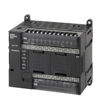
OMRON CP1L-M30D Series Operation Manual (673 pages)
CP1L CPU Unit
Brand:
OMRON
| Category:
Computer Hardware
| Size: 13.19 MB
Table of Contents
Table of Contents
11
About this Manual
14
Related Manuals
16
Precautions
22
General Precautions
23
Intended Audience
23
Safety Precautions
23
Operating Environment Precautions
25
Application Precautions
26
Conformance to EC Directives
29
Applicable Directives
29
Concepts
29
Relay Output Noise Reduction Methods
29
Conditions for Meeting EMC Directives When Using CPM1A Relay Expansion I/O Units
31
Section 1 Features and System Configuration
34
Features and System Configuration
34
Features and Main Functions
35
CP1L Overview
35
Features
38
System Configuration
45
Basic System
45
Optional Products
46
Serial Communications
46
System Expansion
47
Restrictions on System Configuration
50
Connecting the CX-Programmer
53
Connecting with a Commercially Available USB Cable
53
Connecting to a Serial Port
60
Function Charts
62
Function Blocks
63
Advantages of Function Blocks
63
Overview of Function Blocks
63
Section 2 Nomenclature and Specifications
66
Nomenclature and Specifications
66
Part Names and Functions
67
CP1L CPU Units
67
CP1W-CIF01 RS-232C Option Boards
70
CP1W-CIF11 RS-422A/485 Option Boards
71
Specifications
72
CP1L CPU Units
72
Current Consumption
74
I/O Memory Details
77
I/O Specifications
78
Input Specifications
87
Output Specifications
89
CP/CPM1A-Series Expansion I/O Unit I/O Specifications
92
CP1L CPU Unit Operation
95
Overview of CPU Unit Configuration
95
Flash Memory Data Transfers
98
Memory Cassette Data Transfers
100
CPU Unit Operation
102
General Flow
102
I/O Refresh Methods
103
I/O Refreshing and Peripheral Servicing
103
Initialization at Startup
105
CPU Unit Operating Modes
106
Operating Modes
106
Status and Operations in each Operating Mode
106
Operating Mode Changes and I/O Memory
107
Startup Mode Setting
107
Power off Operation
108
Overview
108
Description of Operation
109
Instruction Execution for Power Interruptions
109
Computing the Cycle Time
110
CPU Unit Operation Flowchart
110
Cycle Time Overview
111
Functions Related to the Cycle Time
112
Minimum Cycle Time
112
Cycle Time Calculation Example
114
I/O Refresh Times for PLC Units
114
Online Editing Cycle Time Extension
115
I/O Response Time
116
Interrupt Response Times
117
Serial PLC Link Response Performance
118
Pulse Output Change Response Time
119
Pulse Output Start Time
119
Section 3 Installation and Wiring
120
Installation and Wiring
120
Fail-Safe Circuits
121
Installation Precautions
122
Installation and Wiring Precautions
122
Mounting
124
Mounting in a Panel
124
Connecting Expansion Units and Expansion I/O Units
127
Mounting Height
127
DIN Track Installation
129
Wiring CP1L CPU Units
130
Wiring Power Supply and Ground Lines
131
Wiring Built-In I/O
133
Wiring Safety and Noise Controls
136
Wiring CPU Unit I/O
138
I/O Wiring for CPU Units with 40 I/O Points
138
I/O Wiring for CPU Units with 30 I/O Points
139
I/O Wiring for CPU Units with 20 I/O Points
141
I/O Wiring for CPU Units with 14 I/O Points
143
Pulse Input Connection Examples
144
Pulse Output Connection Examples
145
CP/CPM1A-Series Expansion I/O Unit Wiring
147
Section 4 I\/O Memory Allocation
152
I/O Memory Allocation
152
Overview of I/O Memory Area
153
I/O Memory Area
153
Overview of the Data Areas
154
Clearing and Holding I/O Memory
158
Hot Start/Hot Stop Functions
158
I/O Area and I/O Allocations
160
I/O Bits Allocated to CPU Units
160
I/O Bits Allocated to Expansion I/O Units
162
I/O Allocation Examples with Expansion I/O Units
163
I/O Word Allocations to Expansion Units
165
1:1 Link Area
166
Serial PLC Link Area
167
Internal Work Area
167
Holding Area (H)
168
Auxiliary Area (A)
169
TR (Temporary Relay) Area
169
Timers and Counters
170
Timer Area (T)
170
Counter Area (C)
171
Changing the BCD or Binary Mode for Counters and Timers
173
Data Memory Area (D)
174
Index Registers
175
Using Index Registers
178
Precautions for Using Index Registers
180
Data Registers
182
Task Flags
184
Condition Flags
184
Clock Pulses
186
Section 5 Pulse and Counter Functions
188
Pulse and Counter Functions
188
High-Speed Counters
189
Overview
189
High-Speed Counter Specifications
190
Reset Methods
194
Procedure
195
PLC Setup
196
High-Speed Counter Terminal Allocation
197
Ladder Program Example
201
Pulse Input Connection Examples
201
Additional Capabilities and Restrictions
204
Pulse Outputs
208
Overview
208
Pulse Output Specifications
211
Pulse Output Terminal Allocations
212
Pulse Output Patterns
218
Origin Search and Origin Return Functions
230
Related Auxiliary Area Flags
243
Origin Return
247
Pulse Output Procedures
249
Instructions Used for Pulse Outputs
251
Bits 4 to 7
253
Bits 8 to 11
253
Hex: CW/CCW
253
Hex: Pulse + Direction
253
Advertisement
OMRON CP1L-M30D Series Operation Manual (671 pages)
CP1L CPU Unit
Brand:
OMRON
| Category:
Processor
| Size: 14.96 MB
Table of Contents
Table of Contents
11
About this Manual
14
Related Manuals
16
Precautions
22
General Precautions
23
Intended Audience
23
Safety Precautions
23
Operating Environment Precautions
25
Application Precautions
26
Conformance to EC Directives
29
Applicable Directives
29
Concepts
29
Relay Output Noise Reduction Methods
29
Conditions for Meeting EMC Directives When Using CPM1A Relay Expansion I/O Units
31
Section 1 Features and System Configuration
34
Features and System Configuration
34
Features and Main Functions
35
CP1L Overview
35
Features
38
System Configuration
45
Basic System
45
Optional Products
46
Serial Communications
46
System Expansion
47
Restrictions on System Configuration
50
Connecting the CX-Programmer
53
Connecting with a Commercially Available USB Cable
53
Connecting to a Serial Port
60
Function Charts
62
Function Blocks
63
Advantages of Function Blocks
63
Overview of Function Blocks
63
Section 2 Nomenclature and Specifications
66
Nomenclature and Specifications
66
Part Names and Functions
67
CP1L CPU Units
67
CP1W-CIF01 RS-232C Option Boards
70
CP1W-CIF11 RS-422A/485 Option Boards
71
Specifications
72
CP1L CPU Units
72
Current Consumption
74
I/O Memory Details
77
I/O Specifications
78
Input Specifications
87
Output Specifications
89
CP/CPM1A-Series Expansion I/O Unit I/O Specifications
92
CP1L CPU Unit Operation
96
Overview of CPU Unit Configuration
96
Flash Memory Data Transfers
100
Memory Cassette Data Transfers
102
CPU Unit Operation
104
General Flow
104
I/O Refresh Methods
105
I/O Refreshing and Peripheral Servicing
105
Initialization at Startup
107
CPU Unit Operating Modes
108
Operating Modes
108
Status and Operations in each Operating Mode
108
Operating Mode Changes and I/O Memory
109
Startup Mode Setting
109
Power off Operation
110
Overview
110
Description of Operation
111
Instruction Execution for Power Interruptions
111
Computing the Cycle Time
112
CPU Unit Operation Flowchart
112
Cycle Time Overview
113
Functions Related to the Cycle Time
114
Minimum Cycle Time
114
Cycle Time Calculation Example
116
I/O Refresh Times for PLC Units
116
Online Editing Cycle Time Extension
117
I/O Response Time
118
Interrupt Response Times
119
Serial PLC Link Response Performance
120
2-7-10 Pulse Output Start Time
121
2-7-11 Pulse Output Change Response Time
121
Section 3 Installation and Wiring
122
Fail-Safe Circuits
123
Installation Precautions
124
Installation and Wiring Precautions
124
Mounting
126
Mounting in a Panel
126
Connecting Expansion Units and Expansion I/O Units
129
Mounting Height
129
DIN Track Installation
131
Wiring CP1L CPU Units
132
Wiring Power Supply and Ground Lines
133
Wiring Built-In I/O
135
Wiring Safety and Noise Controls
138
Wiring CPU Unit I/O
140
I/O Wiring for CPU Units with 40 I/O Points
140
I/O Wiring for CPU Units with 30 I/O Points
141
I/O Wiring for CPU Units with 20 I/O Points
143
I/O Wiring for CPU Units with 14 I/O Points
144
Pulse Input Connection Examples
145
Pulse Output Connection Examples
146
CP/CPM1A-Series Expansion I/O Unit Wiring
148
Section 4 I\/O Memory Allocation
154
I/O Memory Allocation
154
Overview of I/O Memory Area
155
I/O Memory Area
155
Overview of the Data Areas
156
Clearing and Holding I/O Memory
160
Hot Start/Hot Stop Functions
160
I/O Area and I/O Allocations
162
I/O Bits Allocated to CPU Units
162
I/O Bits Allocated to Expansion I/O Units
164
I/O Allocation Examples with Expansion I/O Units
165
I/O Word Allocations to Expansion Units
167
1:1 Link Area
168
Serial PLC Link Area
169
Internal Work Area
169
Holding Area (H)
170
Auxiliary Area (A)
171
TR (Temporary Relay) Area
171
Timers and Counters
172
Timer Area (T)
172
Counter Area (C)
173
Changing the BCD or Binary Mode for Counters and Timers
175
Data Memory Area (D)
176
4-11 Index Registers
177
4-11-1 Using Index Registers
180
4-11-2 Precautions for Using Index Registers
182
4-12 Data Registers
184
4-13 Task Flags
186
4-14 Condition Flags
186
4-15 Clock Pulses
188
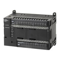
OMRON CP1L-M30D Series Introduction Manual (182 pages)
CP1L/CP1E CPU Unit
Brand:
OMRON
| Category:
Controller
| Size: 10.76 MB
Table of Contents
Table of Contents
5
Precautions
11
Intended Audience
12
General Precautions
12
Safety Precautions
12
Application Precautions
13
Section 1 Cp1L/Cp1E Overview
15
CP1L/CP1E Overview
15
CP1L/CP1E Models
16
CP1L Models
16
CP1E Models
17
Part Names and Functions
19
Section 2 Designing Systems
23
Designing Systems
23
SECTION 2 Designing Systems
23
Organization of this Manual
24
About the Shutter Control System
26
Operation
26
System Components
27
I/O Allocation for the Shutter Control System
28
Example Ladder Program
30
Section 3 Mounting and Wiring
31
Mounting and Wiring
31
Installation Notes
32
Mounting Onto DIN Tracks
35
Wiring Devices
36
Connecting Power Supply and Ground Lines
36
Connecting I/O Lines
37
Power Testing CP1L
39
Section 4 Creating Programs
41
Creating Programs
41
SECTION 4 Creating Programs
41
Preparing for Programming
42
What Is CX-Programmer
42
Connecting to a Computer and Installing the USB Driver
43
Creating Ladder Programs
47
Operation
47
Ladder Program
49
Using CX-Programmer
50
Starting CX-Programmer
50
Operation Screens
51
Using the Help
53
Inputting Programs
55
Creating New Projects
55
Inputting Contacts
58
Inputting Output Coils
62
Inputting Timers
64
Inputting Counters
67
Inputting Auxiliary Areas
72
Inputting Differentiated up Contacts
73
END Instruction
75
Saving/Loading Programs
76
Compiling Programs
76
Saving Programs
77
Loading Programs
78
Editing Programs
79
Editing I/O Comments
79
Inputting Rung Comments
80
Editing Rungs
82
Section 5 Transferring and Debugging Programs
85
Transferring and Debugging Programs
85
Going Online
86
Setting the CP1L Clock
87
Changing the Operating Mode
88
Transferring Programs
90
Executing Operations
92
Adjusting/Debugging Online
93
Monitoring
93
Force-Setting/Force-Resetting
96
Changing Timer Settings (Only CP1L)
97
Searching
97
Online Editing
100
Confirming Cycle Time
101
OMRON CP1L-M30D Series Getting Started Manual (167 pages)
CP1L CPU Unit
Brand:
OMRON
| Category:
Processor
| Size: 15.22 MB
Table of Contents
Table of Contents
4
About this Manual
5
Related Manuals
6
Precautions
10
Intended Audience
11
General Precautions
11
Safety Precautions
11
Application Precautions
11
SECTION 1CP1L Overview
12
CP1L Models
13
Part Names and Functions
16
Section 2 Designing Systems
20
SECTION 2Designing Systems
20
Organization of this Manual
21
Designing Systems
21
About the Shutter Control System
23
Operation
23
System Components
24
I/O Allocation for the Shutter Control System
25
Example Ladder Program
27
Section 3 Mounting and Wiring
28
SECTION 3Mounting and Wiring
28
Installation Notes
29
Mounting and Wiring
29
External Dimensions
31
Mounting Onto DIN Tracks
32
Wiring Devices
33
Connecting Power Supply and Ground Lines
33
Connecting I/O Lines
34
Power Testing CP1L
36
Section 4 Creating Programs
38
SECTION 4Creating Programs
38
Preparing for Programming
39
Creating Programs
39
What Is CX-Programmer
39
Connecting to a Computer and Installing the USB Driver
40
Creating Ladder Programs
45
Operation
45
Ladder Program
47
Using CX-Programmer
48
Starting CX-Programmer
48
Operation Screens
49
Using the Help
51
Inputting Programs
54
Creating New Projects
54
Inputting Contacts
57
Inputting Output Coils
60
Inputting Timers
62
Inputting Counters
64
Inputting Auxiliary Areas
67
Inputting Differentiated up Contacts
69
END Instruction
70
Saving/Loading Programs
71
Compiling Programs
71
Saving Programs
72
Loading Programs
73
Editing Programs
74
Editing I/O Comments
74
Inputting Rung Comments
75
Editing Rungs
76
Section 5 Transferring and Debugging Programs
78
SECTION 5Transferring and Debugging Programs
78
Going Online
79
Setting the CP1L Clock
80
Changing the Operating Mode
81
Transferring Programs
83
Executing Operations
85
Adjusting/Debugging Online
86
Monitoring
86
Force-Setting/Force-Resetting
89
Changing Timer Settings
91
Searching
91
Online Editing
94
Confirming Cycle Time
95
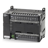
OMRON CP1L-M30D Series Brochure (12 pages)
Compact machine controllers
Brand:
OMRON
| Category:
Controller
| Size: 1.9 MB
Advertisement
Related Products
Omron CP1L-M40D Series
Omron CP1L-M60D Series
OMRON CP1L CPU UNITS - PROGRAMMING 05-2007
OMRON CP1L CPU UNIT - 06-2007
Omron CP1L-EL20DR-D
Omron CP1L-EL20DT1-D
Omron CP1L-EM30DR-D
Omron CP1L-EM40DR-D
Omron CP1L-EM40DT-D
Omron CP1L-EM40DT1-D
Omron Categories
Blood Pressure Monitor
Controller
Accessories
Switch
Inverter
More Omron Manuals
Login
Sign In
OR
Sign in with Facebook
Sign in with Google
Upload manual
Upload from disk
Upload from URL