Sign In
Upload
Manuals
Brands
MAHA Manuals
Measuring Instruments
POWERDYNO MSR 800
MAHA POWERDYNO MSR 800 Manuals
Manuals and User Guides for MAHA POWERDYNO MSR 800. We have
1
MAHA POWERDYNO MSR 800 manual available for free PDF download: Original Operating Instructions
MAHA POWERDYNO MSR 800 Original Operating Instructions (125 pages)
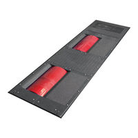
Single Roller Dynamometer
Brand:
MAHA
| Category:
Measuring Instruments
| Size: 9 MB
Table of Contents
Table of Contents
2
1 Safety
7
Introduction
7
Symbols
7
Intended Use
7
Safety Instructions for Commissioning
7
Safety Instructions for Operation
8
Safety Instructions for Servicing
9
Danger Zone
10
Safety Information about Tires
10
Safety Information about the Eddy Current Brake
11
Safety Features
11
Accessories
11
What to Do in the Event of an Accident
11
2 Description
12
General Information
12
Specifications
13
Dimensions
13
Communication Desk
15
Msr 500/1
16
Msr 500/2
17
Msr 500/2 4Wd
18
Msr 500/3 4Wd
19
Msr 800
20
Msr 830
21
Msr 850
22
Msr 1000
23
Msr 1050
24
Main Switch
25
Controls and Indicators
25
Emergency Stop
26
Remote Control
27
Description of the Interface Box
29
RPM Module (Standard)
31
Environmental Module (Standard)
33
OBD Module (Optional)
34
Pressure/Temperature Module (Optional)
34
Analog Input Module (Optional)
35
Analog Output Card (Optional)
35
Measurement Programs
36
Calculation Basis
37
Road Load
37
Torque
38
Extrapolation of the Engine Power with Gasoline Engines
39
Extrapolation of the Engine Power with Diesel Engines (Naturally Aspirated or Supercharged)
40
Extrapolation of the Engine Power with Turbodiesel Engines
41
Calculate Engine Factor Fm
42
Wheel Drive Operation
43
3 Description of the SINAMICS Components
44
Special Safety Instructions for the SINAMICS Components
44
Mains Connection for Booksize Drive Assembly
45
Basic Setup
46
4 Transport and Storage
47
5 Installation and Initial Operation
47
6 Installation
47
Requirements for the Place of Installation
47
Safety Measures
47
Heat Balance
47
Exhaust Suction System
49
Fresh Air Supply for the Test Room
50
7 Software
51
System Requirements
51
Starting the Setup
51
Selecting the Setup Language
52
Selecting the Destination Folder
53
Selecting the SQL Server
53
Selecting the Dyno Type
54
Selecting Features
54
Installing Drivers
55
Finishing the Setup
55
Additional Settings under Windows 7 or Higher
56
8 Preparations for Testing
59
Switch on the Dyno
59
Drive Onto Dyno and Secure Vehicle
59
Connect the RPM Sensor
60
Connect Oil Temperature Probe
61
Attach Exhaust Suction System
61
Position Cooling Air Fan
61
Bring the Vehicle up to Operating Temperature
62
Vehicle Ready for Testing
62
Exit the Dynamometer
62
9 Program Structure
63
General Information
63
Tree Model
64
Screen Design
65
Status Line
65
Main Screen
67
Button Bar
67
Starting the Program
68
End Program / Switch off Dyno
68
10 Measurements
69
Load Simulation
69
Identical Functions
69
Constant Traction
74
Constant Speed
76
Driving Simulation
77
Constant Engine RPM
79
Standstill
79
Drive Dyno
80
Measure Engine Power
80
Display Last Measurement
80
Continuous Measurement
81
Discrete Measurement
84
Engine Flexibility Test
86
Speedometer Check
87
Vehicle Speed
87
Mileage
89
Load Adaption (Optional)
89
Coefficient Adaption Based on ECE
90
Coefficient Adaption Based on SAE J2264
91
Lug-Down Test (Option)
92
11 Settings
93
Database
93
Identical Functions
93
Performance Curves
96
Time Diagram
100
Vehicle Data
101
Load Simulation Profile
102
Driving Cycle Data
104
Vehicle Data
105
RPM Setting
106
Driving Trial
107
Special Settings
108
Select Dyno Type
109
Units
109
Language
110
Device / Interfaces
110
OBD Settings (Optional)
111
12 Diagnosis / Service
112
Dyno Status
112
Driver's Aid Setup (Optional)
112
Test Driving Cycle
113
Edit Profile
114
New Profile
114
Delete Profile
115
Backup/Restore Database
115
Backup Database
115
Restore Database
115
Delete Table
116
Delete Database
116
13 Maintenance
117
Important Information
117
Annual Inspection
117
Maintenance by the Operator
117
Roller Set
117
Eddy Current Brake
117
Bearing Positions
118
Troubleshooting
118
Care Instructions
119
Spare Parts
119
14 Dismantling
119
15 Disposal
119
16 Diagnosis of SINAMICS Components
120
Leds after the Control Unit Has Booted
120
Smart Line Module 16Kw and 36Kw
122
Single Motor Module / Double Motor Module
123
Sensor Module Cabinet 30 (SMC30)
124
17 Company Information
125
Advertisement
Advertisement
Related Products
MAHA POWERDYNO MSR 500
MAHA POWERDYNO MSR 1000
MAHA POWERDYNO MSR 1050
MAHA POWERDYNO MSR 830
MAHA POWERDYNO MSR 850
MAHA Powerdyno MSR 400
MAHA POWERDYNO MSR Series
MAHA MSD 3000
MAHA MSL 4.0 A
MAHA MSL 4.0 U
MAHA Categories
Lifting Systems
Test Equipment
Scissor Lifts
Measuring Instruments
Jacks
More MAHA Manuals
Login
Sign In
OR
Sign in with Facebook
Sign in with Google
Upload manual
Upload from disk
Upload from URL