Sign In
Upload
Manuals
Brands
Magnum Energy Manuals
Remote Control
ME-RC
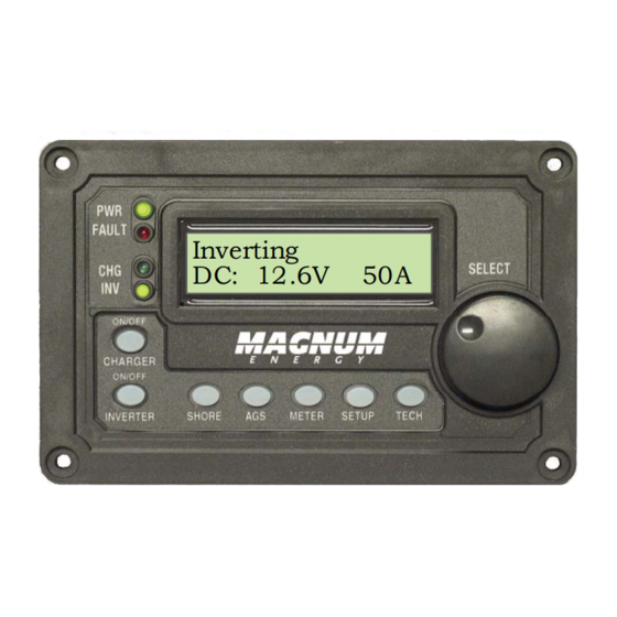
Magnum Energy ME-RC Remote Control Manuals
Manuals and User Guides for Magnum Energy ME-RC Remote Control. We have
3
Magnum Energy ME-RC Remote Control manuals available for free PDF download: Owner's Manual
Magnum Energy ME-RC Owner's Manual (87 pages)
Standard Remote Control
Brand:
Magnum Energy
| Category:
Remote Control
| Size: 1 MB
Table of Contents
Contact Information
2
Table of Contents
4
1 Introduction
8
Figure 1-1, Front Panel Features
8
2 0 Installation
9
Pre-Installation
9
Installation Guidelines
9
Unpacking and Inspection
9
Tools Required
9
Connecting the Remote Cable
10
Connecting the ME-RC to a Magnum Inverter
10
Figure 2-1, Remote Cable
10
Figure 2-2, Remote Control Connections
10
ME-RC Remote Dimensions
11
Mounting the ME-RC Remote
11
Figure 2-3, ME-RC Remote Dimensions
11
Flush Mount Installation Procedure
12
Figure 2-4, Flush Mounting the ME-RC
12
Power-Up Self Test
13
Figure 2-5, Power-Up Self Test Screens
13
Figure 2-6, Example: ME-RC Home Screen
13
3 Setup
14
Navigating the Remote
14
Figure 3-1, Front Panel Setup Features
14
Figure 3-2, SETUP Menu Navigation
15
Remote Feature to Inverter Compatibility
16
Table 3-1, ME-RC (Revision 2.8) Compatibility Matrix
16
Remote Buttons and Menu Items
20
SHORE Menu
20
Figure 3-3, SHORE: Shore Max Selections
20
AGS Menu
21
Figure 3-4, AGS Menu Display
21
METER Menu
22
Figure 3-5, METER: 01 INV/CHG Meter Display
22
SETUP Menu
23
Figure 3-6, SETUP: 01 Search Watts Selections
23
Figure 3-7, SETUP: 02 Lowbattcutout Selections (12V)
24
Figure 3-8, SETUP: 03 Absorb Time Selections
25
Table 3-2, Battery Amphrs Capacity to Suggested Absorb Time
26
Table 3-3, Battery Size to Battery Amphrs (Estimated)
26
Figure 3-9, SETUP: 04 Battery Type Selections
27
Table 3-4, Battery Type to Charge Voltages
28
Figure 3-10, Done Time/Amps Charge Stages
29
Figure 3-11, Hold VDC Charge Stages
31
Figure 3-12, SETUP: 05 Charge Rate Selections
32
Figure 3-13, SETUP: 06 VAC Dropout Selections
33
Figure 3-14, SETUP: 07 Power Save Selections
34
Figure 3-15, SETUP: 08 Screen Setup Selections
34
TECH Menu
36
Figure 3-16, TECH: 01 Temperatures Display
37
Figure 3-17, TECH: 02 Revisions Display
37
Figure 3-18, TECH: 03 Inv Model Display
37
Table 3-5, ME-Rc's Inverter/Charger Default Settings
38
Figure 3-19, TECH: 04 Load Defaults Selection
38
Figure 3-20, TECH: 05 Ext Control Display
39
Figure 3-21, Example: Ext Control Scrolling Screens
39
4 Menu Map: ME-RC Remote Control
41
Figure 4-1, Inverter/Charger Menu Map
41
Figure 4-2, Inverter/Charger Menu Map
42
Figure 4-3, Inverter/Charger Menu Map
43
5 0 Operation
44
Front Panel
44
LED Indicators
44
LCD Display
44
Figure 5-1, ME-RC Front Panel Controls and Indicators
44
ON/OFF Pushbuttons
45
Menu Buttons
45
Rotary SELECT Knob
45
Operating the Inverter/Charger
46
Inverter Mode
46
Charger Mode
46
System Status Messages
47
Inverter Mode Status Messages
47
Figure 5-2, System Status Screen (Example)
47
Figure 5-3, Inverter Standby Mode
47
Figure 5-4, Inverting Mode
47
Charger Mode Status Messages
48
Figure 5-5, off Mode
48
Figure 5-6, Searching Mode
48
Figure 5-7, Absorb Charging Mode
48
Figure 5-8, Bulk Charging Mode
49
Figure 5-9, Charger Standby Mode
49
Figure 5-10, Charging Mode
49
Figure 5-11, Equalizing Mode
50
Figure 5-12, Float Charging Mode
51
Figure 5-13, Full Charge Mode
51
Figure 5-14, Load Support AAC Mode
51
Figure 5-15, Load Support VDC Mode
52
Figure 5-16, Silent Mode
52
Fault Mode Messages
53
5.3.3.1 System Fault Messages
53
Figure 5-17, AC Backfeed Fault
53
Figure 5-18, AC Overload Fault
53
Figure 5-19, Breaker Tripped Fault
54
Figure 5-20, Dead Battery Charge Fault
54
Figure 5-21, FET Overload Fault
54
Figure 5-22, High Battery Fault
55
Figure 5-23, High Battery Temperature Fault
55
Figure 5-24, High Volts AC Fault
56
Figure 5-25, Low Battery Fault
56
Figure 5-26, no Inverter Communication
56
Figure 5-27, Overcurrent Fault
57
Figure 5-28, Overtemp Fault
57
Figure 5-29, Stuck Relay Fault
57
Figure 5-30, Tfmr Overtemp Fault
58
Figure 5-31, Unknown Fault
58
5.3.3.2 Stacking Fault Messages
59
Figure 5-32, Stackclock Fault
59
Figure 5-33, Stack Mode Fault
59
Figure 5-34, Stackphase Fault
59
5.3.3.3 Internal Fault Messages
60
Figure 5-35, Internal Bridge Fault
60
Figure 5-36, Internal Charger Fault
60
Figure 5-37, Internal NTC Fault
60
Figure 5-38, Internal Relay Fault
60
LED Indicator Guide
61
Table 5-1, LED Indicator Guide
61
6 ME-RC Remote Troubleshooting
62
Table 6-1, Remote Control Troubleshooting Guide
62
Inverter/Charger Troubleshooting Tips
63
Inverter Problems
63
Charger Problems
63
Performing an Inverter Reset
64
Performing a Power Reset
64
Figure 6-1, Performing an Inverter Reset
64
7 Using a ME-AGS-N Module
65
ME-AGS-N Setup
65
Table 7-1, ME-RC Autostart/Autostop Matrix
65
Figure 7-1, ME-Rc's AGS Configuration Access Buttons
65
Table 7-2, Battery Amphrs Capacity to Suggested Gen Run Time
66
AGS Functional Tests
69
Remote to Generator Communication Test
69
7.2.1.1 Determining AGS Status
69
7.2.1.2 Starting the Generator from the Remote
69
AGS Operation/Monitoring
69
Controlling the AGS Using the ME-RC
69
Monitoring the AGS Using the ME-RC
70
Enabling the ME-AGS-N Using the ME-RC
72
Starting/Stopping the Generator Using ME-RC
72
ME-AGS-N Menu Map Using the ME-RC
73
Figure 7-2, AGS Menu Maps in ME-RC Remote (Section 1)
73
Figure 7-3, AGS Menu Maps in ME-RC Remote (Section 2)
74
ME-AGS-N Remote Status Messages
75
AGS Remote Operational Statuses
75
Table 7-3, AGS Remote Operational Statuses
75
AGS Remote Start Statuses
76
AGS Remote Fault Statuses
76
General AGS Operational Notes
76
Table 7-4, AGS Remote Start Statuses
76
Table 7-5, AGS Remote Fault Statuses
76
Troubleshooting the ME-AGS-N with the ME-RC
77
AGS Fault Message Screens for the ME-RC Remote
77
Figure 7-4, Example: AGS Fault Message on ME-RC Remote
77
Resolving Operational Statuses
78
Resolving Fault Statuses
78
How to Clear AGS Faults
79
8 Using a ME-BMK
80
Understanding Charge Effi Ciency
80
Accessing the Charge Effi Ciency Menu Item
80
Figure 8-1, Accessing the Charge Efficiency Menu Item
80
Adjusting the Charge Effi Ciency Setting
81
Adjusting the Batt Amphrs Setting
81
Figure 8-2, Adjusting the Charge Efficiency Setting
81
ME-RC50 Remote's BMK METER Menu Maps
82
Figure 8-3, ME-RC50 METER Menu Map (Displays W/Bmk Settings)
82
Operating the BMK Using the ME-RC
83
How the Battery Monitor (ME-BMK) Operates
83
ME-RC METER Menu Items and Settings for BMK
83
9 Service and Warranty Info
86
How to Receive Warranty Service
86
Advertisement
Magnum Energy ME-RC Owner's Manual (46 pages)
Basic Remote Control
Brand:
Magnum Energy
| Category:
Remote Control
| Size: 0 MB
Table of Contents
Table of Contents
3
1 Overview
6
Figure 1-1, Front Panel Features
6
2 Installation
7
Installation Guidelines
7
Tools Required
7
Installation Procedure
7
Figure 2-1, Remote Cut-Out Dimensions
8
Figure 2-2, Remote Control Connections
8
3 Setup
9
Navigating the Remote's Menu
9
Figure 3-1, Front Panel Setup Features
9
Figure 3-2, SETUP Menu Navigation
10
Menu Pushbuttons and Menu Items
11
SHORE Menu
11
Figure 3-3, SHORE: Shore Max Selections
11
AGS Menu
12
METER Menu
12
Figure 3-4, AGS Menu Display
12
Figure 3-5, METER: 01 INV/CHG Meter Display
12
SETUP Menu
13
Figure 3-6, SETUP: 01 Search Watts Selections
13
Figure 3-7, SETUP: 02 Lowbattcutout Selections
14
Table 3-1, Battery Amphrs Capacity to Absorb Time
15
Figure 3-8, SETUP: 03 Absorb Time Selections
15
Table 3-2, Battery Size to Battery Amphrs (Estimated)
16
Table 3-3, Battery Type to Charge Voltages
17
Figure 3-9, SETUP: 04 Battery Type Selections
17
Figure 3-10, SETUP: 05 Charge Rate Selections
18
Figure 3-11, SETUP: 06 VAC Dropout Selections
19
Figure 3-12, SETUP: 07 Power Save Selections
20
Figure 3-13, SETUP: 08 Screen Setup Selections
20
TECH Menu
21
Figure 3-14, TECH: 01 Temperatures Display
21
Figure 3-15, TECH: 02 Revisions Display
21
Figure 3-16, TECH: 03 Inv Model Display
21
Table 3-4, Inverter/Charger Default Settings
22
Figure 3-17, TECH: 04 Load Defaults Selection
22
Figure 3-18, TECH: 05 Ext Control Display
22
4 Menu Map: ME-RC Remote Control
23
Figure 4-1, Inverter/Charger Menu Map
23
Figure 4-2, Inverter/Charger Menu Map
24
Figure 4-3, Inverter/Charger Menu Map
25
5 Operation
26
Front Panel
26
LED Indicators
26
LCD Display
26
Figure 5-1, ME-RC Front Panel Controls and Indicators
26
ON/OFF Pushbuttons
27
Menu Pushbuttons
27
Rotary SELECT Knob
27
Operating the Inverter/Charger
28
Inverter Mode
28
Charger Mode
28
System Status Messages
29
Inverter Mode Messages
29
Figure 5-2, off Mode
29
Figure 5-3, Searching Mode
29
Figure 5-4, Inverting Mode
29
Charger Mode Messages
30
Figure 5-5, Charging Mode
30
Figure 5-6, Bulk Charging Mode
30
Figure 5-7, Absorb Charging Mode
30
Figure 5-8, Float Charging Mode
31
Figure 5-9, Full Charge Mode
31
Figure 5-10, Charger Standby Mode
31
Figure 5-11, Equalizing Mode
32
Fault Mode Messages
33
Figure 5-12, Low Battery Fault
33
Figure 5-13, High Battery Fault
33
Figure 5-14, Overtemp Fault
34
Figure 5-15, AC Overload Fault
34
Figure 5-16, High Volts AC Fault
34
Figure 5-17, Dead Battery Charge Fault
35
Figure 5-18, Overcurrent Fault
35
Figure 5-19, FET Overload Fault
36
Figure 5-20, Breaker Tripped Fault
36
Figure 5-21, Unknown Fault
36
Figure 5-22, Tfmr Overtemp Fault
37
Figure 5-23, no Inverter Comm
37
Figure 5-24, Stackclock Fault
38
Figure 5-25, Stack Mode Fault
38
Figure 5-26, Stackphase Fault
38
Figure 5-27, Internal Bridge Fault
39
Internal Fault Messages
39
Figure 5-28, Internal Charger Fault
39
Figure 5-29, Internal NTC Fault
39
Figure 5-30, Internal Relay Fault
39
LED Indicator Guide
40
Table 5-1, LED Indicator Guide
40
6 Troubleshooting
41
Table 6-1, Remote Control Troubleshooting Guide
41
Troubleshooting Tips
42
Inverter Problems
42
Charger Problems
42
Performing an Inverter Reset
43
Powering-Down the Inverter
43
Figure 6-1, Performing an Inverter Reset
43
7 Limited Warranty
44
How to Receive Repair Service
45
Magnum Energy ME-RC Owner's Manual (44 pages)
Brand:
Magnum Energy
| Category:
Remote Control
| Size: 1 MB
Table of Contents
Remote Control
1
Table of Contents
3
1 Overview
5
Figure 1-1, Front Panel Features
5
2 Installation
6
Installation Guidelines
6
Tools Required
6
Installation Procedure
6
Figure 2-1, Remote Cut-Out Dimensions
7
Figure 2-2, Remote Control Connections
7
3 Setup
8
Navigating the Remote's Menu
8
Figure 3-1, Front Panel Set-Up Features
8
Figure 3-2, SETUP Menu Navigation
9
Menu Pushbuttons and Menu Items
10
SHORE Menu
10
Figure 3-3, SHORE: Shore Max Selections
10
AGS Menu
11
METER Menu
11
Figure 3-4, AGS Menu Display
11
Figure 3-5, METER: 01 INV/CHG Meter Display
11
SETUP Menu
12
Figure 3-6 Thru 3-13, SETUP Menu Selections
12
Table 3-1, Battery Amphrs to Absorb Charging Time
14
Table 3-2, Battery Size to Battery Amp-Hours (Estimated)
15
Table 3-3, Battery Type to Charge Voltages
16
TECH Menu
20
Figure 3-14 Thru 3-18, TECH Menu Displays/Selection
20
Table 3-4, Inverter/Charger Default Settings
21
Menu Items
21
4 Menu Map: ME-RC Remote Control
22
Figure 4-1, Inverter/Charger Menu Map
22
Menu Map
23
5 Operation
24
Front Panel
24
LED Indicators
24
LCD Display
24
Figure 5-1, ME-RC Front Panel Controls and Indicators
24
ON/OFF Pushbuttons
25
Menu Pushbuttons
25
Rotary SELECT Knob
25
Operating the Inverter/Charger
26
Inverter Mode
26
Charger Mode
26
System Status Messages
27
Inverter Mode Messages
27
Figure 5-2, off Mode
27
Figure 5-3, Searching Mode
27
Figure 5-4, Inverting Mode
27
Charger Mode Messages
28
Figure 5-5, Charging Mode
28
Figure 5-6, Bulk Charging Mode
28
Figure 5-7, Absorb Charging Mode
28
Figure 5-8, Float Charging Mode
29
Figure 5-9, Full Charge Mode
29
Figure 5-10, Charger Standby Mode
29
Figure 5-11, Equalizing Mode
30
Fault Mode Messages
31
Figure 5-12, Low Battery Fault
31
Figure 5-13, High Battery Fault
31
Figure 5-14, Overtemp Fault
32
Figure 5-15, AC Overload Fault
32
Figure 5-16, High Volts AC Fault
32
Figure 5-17, Dead Battery Charge Fault
33
Figure 5-18, Overcurrent Fault
33
Figure 5-19, FET Overload Fault
34
Figure 5-20, Breaker Tripped Fault
34
Figure 5-21, Unknown Fault
34
Figure 5-22, Tfmr Overtemp Fault
35
Figure 5-23, Fatal Error $ Fault
35
Figure 5-24, no Inverter Comm
35
Figure 5-25, Stackclock Fault
36
Figure 5-26, Stack Mode Fault
36
Figure 5-27, Stackphase Fault
36
Figure 5-28, Internal Bridge Fault
37
Figure 5-29 Internal Charger Fault
37
Figure 5-30, Internal NTC Fault
37
Figure 5-31, Internal Relay Fault
37
LED Indicator Guide
38
Table 5-1, LED Indicator Guide
38
6 Troubleshooting
39
Table 6-1, Remote Control Troubleshooting Guide
39
Troubleshooting Tips
40
Inverter Problems
40
Charger Problems
40
Performing an Inverter Reset
41
Powering-Down the Inverter
41
Figure 6-1, Performing an Inverter Reset
41
7 Limited Warranty
42
Advertisement
Advertisement
Related Products
Magnum Energy MM Series
Magnum Energy M-RC
Magnum Energy MM-R
Magnum Energy ME-ARC50
Magnum Energy ME-MR
Magnum Energy ME-MR Series
Magnum Energy ME-MR25
Magnum Energy ME-ARC Series
Magnum Energy ME-ARC
Magnum Energy ME-RTR
Magnum Energy Categories
Inverter
Remote Control
Adapter
Battery Charger
Measuring Instruments
More Magnum Energy Manuals
Login
Sign In
OR
Sign in with Facebook
Sign in with Google
Upload manual
Upload from disk
Upload from URL