Sign In
Upload
Manuals
Brands
Magnum Energy Manuals
Control Unit
ME-RTR
Magnum Energy ME-RTR Manuals
Manuals and User Guides for Magnum Energy ME-RTR. We have
1
Magnum Energy ME-RTR manual available for free PDF download: Owner's Manual
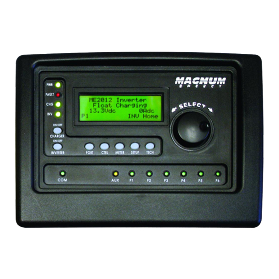
Magnum Energy ME-RTR Owner's Manual (80 pages)
Router Control
Brand:
Magnum Energy
| Category:
Control Unit
| Size: 1.72 MB
Table of Contents
Table of Contents
3
Overview
6
Figure 1-1, Front Panel Features
6
Figure 1-2, Router Connections Overview
7
Installation
8
Installation Guidelines
8
Tools Required
8
Installation Overview
8
Figure 2-1, System Overview
9
Figure 2-2, Router Dimensions
10
Mounting the Router
11
Figure 2-3, Router Mounting Holes
11
Figure 2-4, Internal Router Dimensions
11
Connecting the CAT 5 Parallel Stacking Cables
12
Figure 2-5, Connecting CAT 5 and Communication Cables to Inverters
12
Figure 2-6, Connecting the CAT 5 Cables to the Router
12
Connecting the Communication Cables
13
Optional Cable Connection Routes
14
Figure 2-7, Concealed Mounted Communication Cables
14
Figure 2-8, Surface Mounted Communication Cables
14
Wiring the Auxiliary Relay
15
Figure 2-9, Router Cover's Cable Connection Cutouts
15
Figure 2-10, Wiring the Auxiliary Relay
15
Installing the Router Cover
16
Power-Up Routine
16
Figure 2-11, Installing the Router Cover
16
Figure 2-12, Power-Up Routine
16
Setup
17
Navigating the Router
17
Figure 3-1, up and down Arrows for Hidden Lines
17
Router Pushbuttons and Menu Items
18
PORT Button
18
Figure 3-2, PORT Button
18
CTRL (Control) Button
19
Figure 3-3, CTRL (Control) Button
19
AC in Control
20
CHG (Charge) Control
21
Gen Control
22
METER Button
23
Figure 3-4, METER Button
23
AC Meters
24
DC Meters
24
AGS Meters
25
BMK Meters
25
SETUP Button
27
Figure 3-5, SETUP Button
27
Router Setup
28
Figure 3-6, aux Relay LED
30
Invert Setup
31
Charger Setup
35
Table 3-1, Battery Type to Charge Voltages
36
Table 3-2, Battery Amp/Hrs Capacity to Suggested Absorption Time
38
Accessory Setup
42
AGS Setup
42
BMK Setup
43
REM Setup
43
TECH Button
44
Figure 3-7, TECH Button
44
Figure 3-8, Fault History
45
ME-RTR Menu Maps
48
Figure 4-1 PORT/CTRL Button Menu Maps
48
Figure 4-2 METER Button Menu Map
49
Figure 4-3 SETUP Button Menu Map - Router
50
Figure 4-4 SETUP Button Menu Map - Router
51
Figure 4-5 SETUP Button Menu Map - Inverter
52
Figure 4-6 SETUP Button Menu Map - Charger
53
Figure 4-7 SETUP Button Menu Map - Charger
54
Figure 4-8, SETUP (Accs)/Tech Menu Map (Page 8 of 9
55
Figure 4-9 TECH Button Menu Map
56
Operation
57
Front Panel
57
LED Indicators
57
LCD Display
57
Figure 5-1, ME-RTR Front Panel Controls and Indicators
57
ON/OFF Pushbuttons
58
Menu Pushbuttons
58
Rotary SELECT Knob
58
Operating the Inverter/Charger
59
Inverter Mode
59
Charger Mode
59
System Status Messages
60
Figure 5-1.1, SYSTEM Screen Status Messages
60
Figure 5-1.2, PORT Screen Status Messages
60
Figure 5-2, off Mode
61
Figure 5-3, Searching Mode
61
Figure 5-4, Inverting Mode
61
Inverter Mode Messages
61
Charger Mode Messages
62
Figure 5-5, Inverter Standby Mode
62
Figure 5-6, Charging Mode
62
Figure 5-7, Bulk Charging Mode
62
Figure 5-10, Full Charge Mode
63
Figure 5-8, Absorb Charging Mode
63
Figure 5-9, Float Charging Mode
63
Figure 5-11, Charger Standby Mode
64
Figure 5-12, Silent Mode
64
Figure 5-13, Force Float Mode
64
Figure 5-14, Equalizing Mode
65
AC in Control Messages
66
Fault Mode Messages
66
Figure 5-15, VDC Connect Mode
66
Figure 5-16, Time Connect Mode
66
Figure 5-17, AC in - Disabled Mode
66
Figure 5-18, Low Battery Fault
67
Figure 5-19, High Battery Fault
67
System Fault Messages
67
Figure 5-20, Overtemp Fault
68
Figure 5-21, AC Overload Fault
68
Figure 5-22, Hi Volts AC Fault
68
Figure 5-23, Dead Battery Charge Fault
69
Figure 5-24, Overcurrent Fault
69
Figure 5-25, FET Overload Fault
69
Figure 5-26, Breaker Tripped Fault
70
Figure 5-27, Unknown Fault XX
70
Figure 5-28, Transformer Overtemp Fault
70
Figure 5-29, no Inverter Comm Fault
71
Figure 5-30, Stackclock Fault
71
Figure 5-31, Stack Mode Fault
71
Stacking Fault Messages
71
Figure 5-32, Stackphase Fault
72
Figure 5-33, Internal Bridge Fault
72
Figure 5-34, Internal Charger Fault
72
Internal Fault Messages
72
Figure 5-35, Internal NTC Fault
73
Figure 5-36, Internal Relay Fault
73
LED Indicator Guide
74
Table 5-1, LED Indicator Guide
74
Troubleshooting
75
Table 6-1, Router Control Troubleshooting Guide
75
Troubleshooting Tips
76
Charger Problems
76
Inverter Problems
76
Performing an Inverter Reset
77
Powering down the Inverter
77
Figure 6-1, Performing an Inverter Reset
77
Warranty and Service Info
78
Limited Warranty
78
How to Receive Repair Service
79
Advertisement
Advertisement
Related Products
Magnum Energy ME-RC
Magnum Energy ME Series
Magnum Energy ME-BMK
Magnum Energy ME-ARC50
Magnum Energy ME-AGS-N
Magnum Energy ME2000-20B
Magnum Energy ME2012-20B
Magnum Energy ME3012
Magnum Energy ME-MR25
Magnum Energy ME-MW-E
Magnum Energy Categories
Inverter
Remote Control
Adapter
Battery Charger
Measuring Instruments
More Magnum Energy Manuals
Login
Sign In
OR
Sign in with Facebook
Sign in with Google
Upload manual
Upload from disk
Upload from URL