Sign In
Upload
Manuals
Brands
M&C Manuals
Accessories
EC-30C
M&C EC-30C Gas Cooler Manuals
Manuals and User Guides for M&C EC-30C Gas Cooler. We have
1
M&C EC-30C Gas Cooler manual available for free PDF download: Instruction Manual
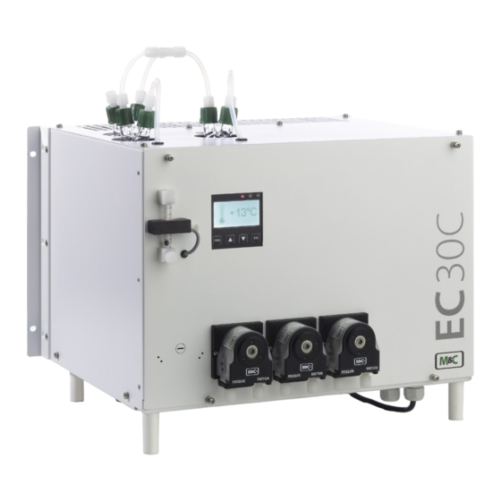
M&C EC-30C Instruction Manual (78 pages)
Ultra Low Gas Cooler
Brand:
M&C
| Category:
Accessories
| Size: 7 MB
Table of Contents
Table of Contents
3
1 About this Instruction Manual
7
2 Important Safety Information
8
Intended Use
8
Personal Safety
8
Warning Signs and Definitions
8
Safety Instructions
9
Working on Electrical and Electronic Devices
10
Not Certified in Hazardous Areas
10
3 Introduction
11
4 Product Overview
12
Application
12
Fig. 1: Application Example of the EC-30C
12
Principle
13
Fig. 2: Jet-Stream Heat Exchanger
13
5 Technical Data
15
Max. Possible Water Vapor Dew Point Input [°C] / [°F]
16
Dimensions
17
Fig. 3: Front View: Dimensions Including Optional Peristaltic Pumps
17
Fig. 4: Side View: Dimensions Including Optional Peristaltic Pumps
17
6 Receiving the EC-30C
18
Product Label and Serial Number
18
7 Using the EC-30C
19
Graphical User Interface (GUI)
19
LED Color Coding and Possible Color Combinations
19
Fig. 5: Graphic User Interface
19
Self-Monitoring after Powering-On the Unit
20
Fig. 6: Smiley Symbols During Self-Test
20
Fig. 7: the Smileys on the Display after Self-Testing
20
Self-Monitoring During Operation
21
Power Consumption Readjustment
21
Pre-Warning Messages
21
Fig. 8: 'Service'-Monitor: Self-Test Failed
21
Display During Start-Up of the EC-30C
22
Fig. 9: Start-Up Phase: First Cooling Phase
22
Fig. 10: Start-Up Phase: TKS Reaches And/Or Exceeds '0 °C / 32 °F'-Limit
23
Fig. 11: Start-Up Phase: Target Temperature Reached
23
Overview Screen
24
Fig. 12: That's How You Reach the Overview Screen
24
Fig. 13: Overview Screen
24
Alarm and Warning History
25
Fig. 14: How to Reach the Alarm and Warning History
25
Fig. 15: Alarm and Warning History
26
Fig. 16: How to Chose an Alarm or Warning Message
26
Fig. 17: How to Scroll through Stored Messages
27
Fig. 18: Detailed Information for a Selected Message
27
Error Codes
28
Warning Symbols
28
Alarm Symbols
30
Temperature Diagrams
33
Diagram of the Pre-Cooler Unit (PCU)
33
Fig. 19: How to Reach the Graphical Temperature Diagrams
33
Fig. 20: Temperature Diagram of the Pre-Cooling Unit
33
Diagram of the Deep Cooling Units (DCU 1 and DCU 2)
34
Fig. 21: Temperature Diagram of the Deep-Cooling Units
34
Parameter Menu
35
Fig. 22: How to Reach the Parameter Menu (Screen 1)
35
Fig. 23: Parameter Menu, Screen 1
35
Fig. 24: Parameter Menu, Screen 2
36
Fig. 25: How to Reach the Parameter Settings
37
Parameter Settings
37
Device Information
38
Fig. 26: How to Reach the Device Information
38
Fig. 27: Device Information
39
Service-Reset (Qualified Personnel Only)
40
Fig. 28: Activating Service Reset (Qualified Personnel Only)
40
Fig. 29: Reset Screen (Qualified Personnel Only)
40
8 Installation Instructions and Mounting of the EC-30C
41
Installation Instructions
41
Wall and Rack Mount
42
Fig. 30: Min. Assembly Dimensions (Unit with Optional Peristaltic Pumps)
42
Fig. 31: Mounting Rail for Wall or Rack Mounting
43
Mounting Instructions for SR25.2 Peristaltic Pump (Optional)
44
Fig. 32: SR25.2: Mounting Distance between Pump Motor and Front Panel
44
Tubing Without Heat Exchanger Purging (Standard Tubing)
45
Heat Exchanger Connections for Tubing Without Purging
45
Fig. 33: Standard Tubing: DCU 1 Active, Solenoid Valve Triggered, no FA
45
Fig. 34: Heat Exchanger Connectors (Device with Four Optional Peristaltic Pumps)
46
Tubing with Heat Exchanger Purging for Special Requirements (Optional)
47
Fig. 35: Tubing with Purging: DCU 1 Activ, Solenoid Valves Triggered, no FA
47
Fig. 36: Heat Exchanger Connections, Tubing with Purging
48
Heat Exchanger Connections for Tubing with Purging
48
Duran-Glass Heat Exchanger with GL-Connections
49
PVDF- Heat Exchanger with PVDF-Tube Connectors
49
Electrical Connections
50
Fig. 37: Electrical Connections
51
Liquid Alarm Sensor la (Optional)
52
Ma-Output
52
Gas Flow Sensor FA 20 and Gas Flow Meter FM 40 (Optional)
53
9 Start-Up
54
Preparation for Start-Up
54
Temperature Chart of the Start-Up Stages
55
Fig. 38: Temperature Chart of the Start-Up Stages
56
10 Maintenance
59
Maintenance of the Peristaltic Pump Type SR25.2 (Optional)
59
Changing the Pump Tubing
60
Fig. 39: Changing the Pump Tubing
60
Changing the Contact Pulley and Springs
61
Cleaning the Pump Head
61
Changing the Heat Exchanger
62
Changing the 0-20 V-Module
63
Changing the Buffer Battery
64
Checking the Temperature Sensors
65
Fig. 40: Resistor - Temperature Characteristic of the PT100
65
Changing the Compressor Unit
66
Fig. 41: Compressor: Electrical Connections
66
11 Decommissioning
67
12 Appendix
68
Overview of the EC-30C Screens
68
Fig. 42: Overview: Screens
68
How to Configure the Ma-Output
69
How to Calculate Temperature Based on Measured Ma-Value
69
How to Calculate Ma-Value Based on Measured Temperature
70
Spare Parts and Consumables
71
Additional Information
72
Declaration of Conformity
72
Certificates
73
Warranty
73
Liability and Disclaimer
73
Storage
74
Shipping and Handling
74
Proper Disposal of the Device
74
Ec-30C
78
Advertisement
Advertisement
Related Products
M&C ECM Series
M&C ECM-1
M&C ECM-2
M&C EC Series
M&C ECM-ExII
M&C ECS Series
M&C EC-30
M&C EC-30/FD
M&C ECP 3000
M&C ECP 2000
M&C Categories
Measuring Instruments
Water Pump
Accessories
Laboratory Equipment
Industrial Equipment
More M&C Manuals
Login
Sign In
OR
Sign in with Facebook
Sign in with Google
Upload manual
Upload from disk
Upload from URL