M&C EC Series Manuals
Manuals and User Guides for M&C EC Series. We have 6 M&C EC Series manuals available for free PDF download: Instruction Manual

Advertisement


M&C EC Series Instruction Manual (40 pages)
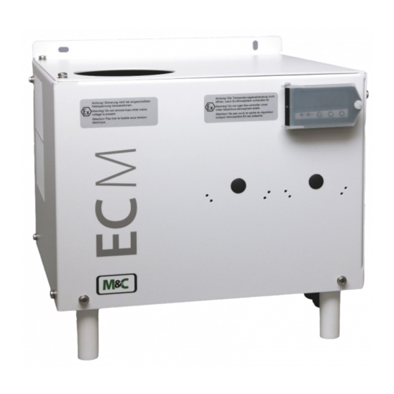
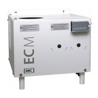
Electric gas cooler
Brand: M&C
|
Category: Accessories
|
Size: 2 MB
Table of Contents
Advertisement
M&C EC Series Instruction Manual (40 pages)
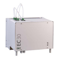
Ultra Low Gas Cooler
Brand: M&C
|
Category: Accessories
|
Size: 2 MB
Table of Contents

M&C EC Series Instruction Manual (41 pages)
Electric Gas Cooler
Brand: M&C
|
Category: Accessories
|
Size: 5 MB
Table of Contents
M&C EC Series Instruction Manual (29 pages)
Electric Gas Cooler
Brand: M&C
|
Category: Accessories
|
Size: 2 MB
Table of Contents
Advertisement