Sign In
Upload
Manuals
Brands
Lenze Manuals
Controller
8400 HighLine C
Lenze 8400 HighLine C Manuals
Manuals and User Guides for Lenze 8400 HighLine C. We have
2
Lenze 8400 HighLine C manuals available for free PDF download: Hardware Manual
Lenze 8400 HighLine C Hardware Manual (308 pages)
E84A Series
Brand:
Lenze
| Category:
DC Drives
| Size: 5 MB
Table of Contents
Table of Contents
3
About this Documentation
8
Document History
8
Conventions Used
9
About this Documentation
9
Terms and Abbreviations Used
10
Notes Used
11
2 Safety Instructions
12
General Safety and Application Notes for Lenze Controllers
12
General Safety and Application Instructions for Lenze Motors
15
Residual Hazards
18
3 Product Description
19
Device Features
19
Overview of Standard Devices
20
Overview of Control Terminals
23
Identification
25
Product Key
26
4 Technical Data
27
General Data and Operating Conditions
27
Technical Data
28
Rated Data
33
Overview
33
Rated Data
34
Operation at Rated Mains Voltage 230 V
36
Operation at Rated Mains Voltage 400 V
40
Operation at a Rated Mains Voltage of 500 V
47
Operation at a Rated Mains Voltage of 500 V
48
Operation with Increased Power at a 230 V Mains
54
Operation with Increased Power at a 400 V Mains
57
Operation with Increased Power at a 500 V Mains
62
Current Characteristics
67
Overcurrent Operation
71
Terminal Description
73
Overview
73
Stateline C Control Terminals
77
External Supply Voltage
77
Analog Inputs
78
Analog Outputs
78
Stateline C Control Terminals
78
Digital Inputs
79
Digital Outputs
79
Connection of Relay Output
79
Highline C Control Terminals
80
External Supply Voltage 24 V
80
Analog Inputs
81
Analog Outputs
81
Digital Inputs
82
Digital Outputs
82
Connection of Relay Output
82
Motor Holding Brake Connection
83
Topline C Control Terminals
84
Axis Bus
84
Multi-Encoder Connection
85
Topline C Control Terminals
85
Resolver Connection
87
5 Mechanical Installation
88
Important Notes
88
Standard Devices in a Power Range of 0.25
89
Assembly in Built-In Technique (Standard)
89
Assembly in Push-Through Technique (Thermal Separation)
98
Assembly in Push-Through Technique (Thermal Separation)
99
Mounting in "Cold Plate" Technique
103
Mounting in "Cold Plate" Technique
104
Standard Devices in the Power Range 3
112
Assembly in Built-In Technique (Standard)
112
Assembly in Push-Through Technique (Thermal Separation)
121
Assembly in Push-Through Technique (Thermal Separation)
122
Mounting in "Cold Plate" Technique
129
Mounting in "Cold Plate" Technique
130
Standard Devices in a Power Range of 30
138
Assembly in Built-In Technique (Standard)
138
Mounting in "Cold Plate" Technique
148
Mounting in "Cold Plate" Technique
149
6 Electrical Installation
153
Important Notes
153
Electrical Installation
154
Electrical Isolation
157
Device Protection
158
Interaction with Compensation Equipment
159
Maximum Motor Cable Length
159
Motor Protection
159
Safety Instructions for the Installation According to UL or UR
160
Safety Instructions for the Installation According to UL or UR
164
Installation According to EMC (Installation of a CE-Typical Drive System)
168
Shielding
168
Mains Connection, DC Supply
170
Motor Cable
171
Control Cables
172
Installation in the Control Cabinet
173
Wiring Outside of the Control Cabinet
175
Detecting and Eliminating EMC Interferences
177
Devices in the Power Range 0.25
178
Example Circuits
178
Terminal Assignment of the Power Connections
182
Terminal Assignment of the Power Connections
183
Devices in the Power Range 0.37
189
Example Circuits
189
Terminal Assignment of the Power Connections
192
Terminal Assignment of the Power Connections
193
Devices in a Power Range of 30
201
Example Circuits
201
Terminal Assignment of the Power Connections
202
Terminal Assignment of the Power Connections
203
Common Control Terminals
211
Important Notes
211
System Bus Connection (Canopen)
215
Connection of Relay Output
221
Connection of Relay Output
222
Diagnostics
223
Stateline C Control Terminals
224
External Supply Voltage 24 V
224
Analog Inputs and Outputs
225
Analog Inputs and Outputs
226
Digital Inputs and Outputs
228
Digital Inputs and Outputs
229
Highline C Control Terminals
230
External Supply Voltage 24 V
230
Analog Inputs and Outputs
232
Analog Inputs and Outputs
233
Digital Inputs and Outputs
235
Digital Inputs and Outputs
236
Motor Holding Brake Connection
238
Topline C Control Terminals
239
Resolver Connection
239
Encoder Connection
240
Topline C Control Terminals
240
Axis Bus
241
7 Commissioning
243
Before Switching on
243
Quick Commissioning
246
Keypad Control
247
Terminal Control
249
8 Braking Operation
251
Braking Operation Without Additional Measures
251
Braking Operation with External Brake Resistor
252
Operation at Rated Mains Voltage 230 V
252
Operation at Rated Mains Voltage 400 V
253
Braking Operation with External Brake Resistor
253
Operation at a Rated Mains Voltage of 500 V
254
Selection of the Brake Resistors
255
Rating for Lenze Brake Resistors
256
Wiring of Brake Resistor
258
Operation with Spring-Applied Brake
260
Introduction
260
Rated Data
262
Rated Data
263
Wiring
264
9 Diagnostics
267
Display of Operating Data, Diagnostics
267
Status Display Via Controller Leds
267
Drive Diagnostics Via Keypad
270
10 Safety Engineering
272
Introduction
272
Important Notes
273
Hazard and Risk Analysis
274
Standards
274
Mission Time
275
Acceptance
276
Description
276
Periodic Inspections
276
Basics for Safety Sensors
277
Operating Mode
278
Hardware Revision
280
Technical Data
281
Technical Data
282
Description
284
Electrical Installation
285
Electrical Installation
286
Certification
287
11 Accessories (Overview)
288
Overview
288
Mains Chokes
289
RFI Filter/Mains Filter
291
Sinusoidal Filters
293
External Brake Resistors
294
Memory Module
295
E84Aym10S
295
Communication Modules
296
Keypad
297
Power Supply Units
298
Terminals (Replacement)
299
EMC Accessories
301
Accessories for Applications with Digital Frequency
304
12 Appendix
305
Total Index
305
Validity
307
Td15
308
Advertisement
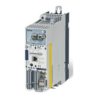
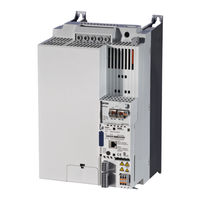
Lenze 8400 HighLine C Hardware Manual (187 pages)
L-force Drives Frequency Inverter
Brand:
Lenze
| Category:
Controller
| Size: 3 MB
Table of Contents
Table of Contents
3
1 About this Documentation
7
Document History
7
Supplemented by Devices of Device Size
7
Conventions Used
8
Terms and Abbreviations Used
9
Notes Used
10
2 Safety Instructions
11
General Safety and Application Notes for Lenze Controllers
11
General Safety and Application Instructions for Lenze Motors
14
Residual Hazards
17
3 Product Description
18
Device Features
18
Overview of Standard Devices
19
Overview of Control Terminals
20
Identification
21
Type Code
22
4 Technical Data
23
General Data and Operating Conditions
23
Rated Data
27
Overview
27
Operation at Rated Mains Voltage 230 V
30
Operation at Rated Mains Voltage 400 V
34
Operation at Rated Mains Voltage 500 V
40
Current Characteristics
46
Overcurrent Operation
50
Terminal Description
52
Overview
52
Stateline C Control Terminals
54
External Supply Voltage 24 V
54
Analog Inputs
55
Analog Outputs
55
Digital Inputs
56
Digital Outputs
56
Relay Output Connection
56
Highline C Control Terminals
57
External Supply Voltage
57
Analog Inputs
58
Analog Outputs
58
Digital Inputs
59
Digital Outputs
59
Relay Output Connection
59
Motor Holding Brake Connection
60
5 Mechanical Installation
61
Important Notes
61
Standard Devices in the Power Range 0.25
62
Assembly in Built−In Technique (Standard)
62
Assembly in Push−Through Technique (Thermal Separation)
68
Mounting in "Cold Plate" Technique
69
Standard Devices in the Power Range 3
71
Assembly in Built−In Technique (Standard)
71
Assembly in Push−Through Technique (Thermal Separation)
77
Mounting in "Cold Plate" Technique
79
6 Electrical Installation
82
Important Notes
82
Electrical Isolation
85
Device Protection
87
Maximum Motor Cable Length
87
Motor Protection
87
Interaction with Compensation Equipment
87
Safety Notes for the Installation According to UL or UR
88
Installation According to EMC (Installation of a Ce−Typical Drive System)
90
Shielding
90
Mains Connection, DC Supply
92
Motor Cables
93
Control Cables
94
Installation in the Control Cabinet
95
Wiring Outside the Control Cabinet
97
Detecting and Eliminating EMC Interferences
99
Devices in the Power Range 0.25
100
Example Circuits
100
Terminal Assignment of the Power Connections
103
Devices in the Power Range 0.37
110
Example Circuits
110
Terminal Assignment of the Power Connections
112
Common Control Terminals
121
Important Notes
121
System Bus Connection (Canopen)
124
Relay Output Connection
125
Diagnostics
127
Stateline C Control Terminals
128
External Supply Voltage 24 V
128
Analog Inputs and Outputs
129
Digital Inputs and Outputs
131
Highline C Control Terminals
133
External Supply Voltage
133
Analog Inputs and Outputs
135
Digital Inputs and Outputs
137
Motor Holding Brake Connection
140
7 Commissioning
141
Before Switching on
141
Quick Commissioning
144
Keypad Control
145
Terminal Control
147
8 Braking Operation
149
Braking Operation Without Additional Measures
149
Braking Operation with External Brake Resistor
150
Operation at Rated Mains Voltage 230 V
150
Operation at Rated Mains Voltage 400 V
151
Braking Operation with External Brake Resistor
151
Operation at Rated Mains Voltage 500 V
152
Selection of the Brake Resistors
153
Rating for Lenze Brake Resistors
154
Wiring of Brake Resistor
155
Operation with Spring−Applied Brake
157
Introduction
157
Rated Data
159
Wiring
161
9 Diagnostics
163
Display of Operating Data, Diagnostics
163
Status Display Via Leds at the Controller
163
Drive Diagnostics Via Keypad
165
10 Safety Engineering
167
Introduction
167
Important Notes
168
Hazard and Risk Analysis
169
Standards
169
Overview of Sensors
170
Operating Mode
171
Technical Data
172
Electrical Installation
173
Certification
174
11 Accessories (Overview)
175
Overview
175
Mains Chokes
176
RFI Filters
177
Sinusoidal Filters
178
External Brake Resistors
179
Memory Module
180
Communication Modules
181
Keypad
182
Power Supply Units
183
12 Appendix
184
Total Index
184
Advertisement
Related Products
Lenze 8400 TopLine C
Lenze 8400 HighLine C Series
Lenze 8400 BaseLine C
Lenze L-force 8400 E84AVTCE3712
Lenze L-force 8400 E84AVTCE5512
Lenze L-force 8400 E84AVTCE2222
Lenze L-force 8400 E84AVTCE3024
Lenze L-force 8400 E84AVTCE751
Lenze L-force 8400 E84AVTCE152
Lenze 8400 protec Series
Lenze Categories
DC Drives
Control Unit
Inverter
Engine
Controller
More Lenze Manuals
Login
Sign In
OR
Sign in with Facebook
Sign in with Google
Upload manual
Upload from disk
Upload from URL