Sign In
Upload
Manuals
Brands
JRC Manuals
Marine Radar
JMR-7225-6X
JRC JMR-7225-6X Manuals
Manuals and User Guides for JRC JMR-7225-6X. We have
7
JRC JMR-7225-6X manuals available for free PDF download: Field Service Manual, Instruction Manual, Installation Manual, Quick Operation Manual
JRC JMR-7225-6X Field Service Manual (1078 pages)
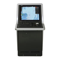
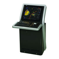
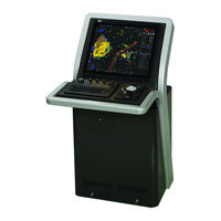
MARINE RADAR EQUIPMENT, ECDIS CONNING DISPLAY
Brand:
JRC
| Category:
Marine Radar
| Size: 49.9 MB
Table of Contents
Contents
29
Table of Contents
31
Chapter 1 System Overview
39
Functions
41
Features
43
Scanner Units
46
Transmitter Receiver Units
49
Display Units
50
Chapter 2. System Configuration
55
Components
59
Power System Diagram
65
Function System Diagrams
71
Scanner Unit / Transmitter-Receiver Unit
71
Display Unit
77
I/O Specifications
81
CCU : Central Control Unit NDC-1590 I/O Specifications
81
PSU : Power Supply Unit NBD-913 I/O Specifications
88
SLC : Serial LAN Interface Circuit CMH-2370
91
AOC : Analog Option Circuit CMJ-560 I/O Specifications
101
GIF : Gyro Interface Circuit CMJ-554 I/O Specifications
103
RIF :Radar Interface Circuit CQD-2273 I/O Specifications
105
DIP-SW and Jumper Pin Settings
111
Setting for CQD-2273 Radar Interface Circuit
111
Settings for CMJ-554 Gyro Interface Circuit
113
Settings for CMH-2370 Serial LAN Interface Circuit
117
Settings for CMJ-560 Analog Option Circuit
130
Settings for NDC-1590 Central Control Unit: CCU
133
Settings for T/R Control Circuit CMC-1205R
137
Settings for NKE-1632 Scanner Unit
138
Settings for NKE-2632 Scanner Unit
139
Settings for NKE-2632-H Scanner Unit
140
Setting for UPS
141
Settings for Interswitch
142
Chapter 3. Repair Parts
147
List of Repair Parts
149
Parts Required for Periodic Replacement
149
Spares
150
Special Parts
150
Circuit Blocks
153
Exploded View Drawings
161
Chapter 4. Replacement Procedure
219
Replacement Procedures for Scanner Unit
222
Scanner Unit
222
Scanner Unit
228
Replacement Procedures for Display Unit
531
Inch Monitor Unit: MNU NWZ-208
535
Inch Monitor Unit: MNU NWZ-207
542
Inch Monitor Unit: MNU NWZ-214
549
Central Control Unit: CCU NDC-1590
554
Trackball Operation Unit: TOPU NCE-5605
615
Keyboard Operation Unit: KOPU NCE-5625
635
Power Supply Unit: PSU NBD-913
643
Junction Box: JB NQE-1143
652
Relay Terminal Block: CQD-2312
681
Sensor LAN Switch Unit: NQA-2443
692
Replacing the UPS
704
Detaching the Front Frame of the Display Unit Mount Kit
727
Setting up after Replacements
735
To Display the Service Menu for Engineers
735
Displaying the "Maintenance" Dialog Box
736
Setting up Anfter Replacing Scanner Units
737
Setting up Anfter Replacing Display Units
740
Chapter 5. Software Update
742
Updating the Software
744
Backing Up/Recovering Data
748
Backing up Data
748
Restoring Backup Data
750
Recovering the C Drive Image
752
Advertisement
JRC JMR-7225-6X Instruction Manual (668 pages)
Marine Radar Equipment
Brand:
JRC
| Category:
Marine Radar
| Size: 27.64 MB
Table of Contents
Table of Contents
3
Basic Operation of the Radar
17
Overview Flowchart
17
Starting and Shutting down the Radar
19
Powering on and Starting
19
Exiting Radar Operation
22
Observation Environment and Image Adjustment
23
Adjusting Screen Brightness
23
Changing the Observation Range
23
Adjusting Tune
25
Adjusting Gain
26
Rejecting Sea Clutter (Sea)
28
Rejecting Rain/Snow Clutter
30
Adjusting to Optimal Images (Selection of Observation Scenes)
32
General Radar Operation
35
Interference Rejection (IR Function)
35
Changing the Transmitter Pulse Length
36
Enhancing Targets
37
Using Video Processing (Echo Process)
38
Setting the Azimuth Mode
39
Setting a Motion Mode
41
Resetting Own Ship to Its Initial Position in [TM] (True Motion Display) Mode
42
Setting the Stabilization Mode
43
Moving Own Ship's Display Position (off Center)
43
Displaying Other Ship's Trails (Trails)
44
Trails Motion Mode
44
Changing Motion Mode of Trails
46
Setting the Length of the Trail
46
Clearing Trails Data
47
Doubling the Size of Radar Image
48
Hiding the Heading Line (HL OFF)
50
Hiding Graphics Information on Radar Display
51
Setting True Bearing
51
Setting Own Ship Speed
52
Switching Own Ship Speed Device
52
Entering the Ship's Heading/Own Ship's Speed Manually
54
Target Tracking and AIS
55
Restrictions
56
Collision Avoidance Issue (Explanation)
57
Collision Avoidance in Navigation
57
Marine Accidents and Collisions
57
Basic Concept of Collision Avoidance
58
Relative Vector and True Vector
59
Radar and Collision Avoidance
59
Displaying Symbols
60
Displaying/Hiding Target Tracking Symbols/Ais Target Symbols
60
Types and Definitions of Target Tracking Symbols
60
Types and Definitions of AIS Target Symbols
61
About AIS Aton (Aids to Navigation)
66
About AIS-SART Information
66
About Display Priority of AIS Targets
67
Switching between Ground Vector and Water Vector
68
Association Target Symbols
68
Preparation
69
Setting the Cursor Mode to AUTO Mode
69
Setting Vector
69
Vector Modes
69
Setting Vector Mode
71
Vector Length (Vector Time)
71
Setting the Vector Length
72
Setting Collision Decision Criteria
72
Setting CPA Limit
72
Setting TCPA Limit
73
Showing the CPA Ring (RADAR Only)
74
Setting and Operating Target Tracking
75
Acquiring Target
75
Automatic Acquisition (Automatic Acquisition) Mode
75
ACQ MANUAL (Manual Acquisition) Mode
76
Using Manual Acquisition and Auto Acquisition Together
77
Setting up the Automatic Acquisition/Activation Zone (AZ)
77
Using [New Target Warning] Dialog Box in the [Alert] Menu
78
Using the Cursor
79
Using the EBL/VRM Dial for the Setting
80
Tracked Target Information Display
81
Erasing Unwanted Tracked Targets
82
Displaying Target ID no
83
Editing Tracked Target Properties
85
Adding Tracked Target ID Name
85
Setting Track Color of Tracked Target
87
Setting Target for Which Ground Is Fixed to a Reference Target
88
Operation Test for Target Tracking
90
Test Video]
91
TT Simulator] (Target Tracking Simulator)
92
Gate Display]
94
Status] Display
96
Setting and Operating AIS
97
Enabling AIS Function
97
Activating AIS Targets (Activate AIS)
97
Manual Activation
97
Automatic Activation
98
Deactivating AIS Targets
98
Displaying AIS Information
99
Displaying Target ID no
107
Checking and Setting AIS Target Property
108
Setting Track Color of AIS Target
108
Conditions for Deciding AIS Target to be Lost
109
Alert Display
110
Danger Target Alarm (CPA/TCPA)
111
Alarm for New Target Acquired in Automatic Acquisition Guard Zone (New Target)
112
Lost Target Notification (Lost)
113
Target Tracking Function Alarm (TT Data)
114
Gyro Set Notification (Set Gyro)
114
Track Function
115
Setting the Past Position
115
Setting the Other Ship's Tracks
115
Setting Track Color
116
Turning On/Off Other Ship's Track Function
116
Setting Other Ship's Track Colors
116
Turning On/Off Other Ship's Track Display
116
Setting up the Display Interval of Other Ship's Track
117
Clearing Other Ship's Track
117
Saving and Loading Other Ship's Track Data
117
Entering Own Ship's AIS Voyage Data
118
Editing and Sending AIS Messages
119
AIS Message Tray
122
Displaying the AIS Message Tray
122
Switching Message Display
124
Sending a Message in the Message Tray after Editing
125
Highlighting TT/AIS Symbols
126
Trial Maneuvering
128
Outline of Trial Maneuvering
128
Performing a Trial Maneuver
131
Displaying the TT/AIS Target List
133
Displaying TT/AIS List
133
Switching between a Standard Window and an Extended Window
134
TT List
136
AIS List
137
Confirming Own Ship's AIS Information
139
Displaying the Last Lost AIS Target
140
True and False Echoes on Display
145
Radar Wave with the Horizon
145
Intensity Reflected from the Target
147
Sea Clutter and Rain/Snow Clutter
149
Sea Clutter
149
Rain and Snow Clutter
150
Coping with Sea Clutter and Rain/Snow Clutter
152
False Echoes
153
Shadow
153
Side Lobe Effect
153
False Echo by Secondary Reflection
154
False Echo by Multiple Reflection
155
Second Time Echoes
155
Radar Interference
156
Radar Transponder (SART) Screen Display
157
Display of AIS-SART
159
Radar Screen Display Example
159
Numeric Data Display Example
160
Functions of the ECDIS (Option)
161
General Flowchart
161
Work Flowchart While Sailing
162
Starting and Preparing the ECDIS
163
Powering on and Starting
163
Starting the ECDIS
164
Starting the ECDIS from the Task Menu
164
Starting ECDIS from a Non-ECDIS Task Screen
165
Entering an ARCS PIN Number (ARCS Only)
166
Moving the Chart
167
Moving the Chart with the [HOME] Button
167
Moving the Chart with the Cross-Hair Cursor
168
Moving the Chart with the Hand Cursor
169
Switching a Chart to be Displayed by [My Port List]
170
Displaying the Chart by Entering the Position
171
Zooming In/Out the Chart
172
Enlarging a Selected Area (S-57/C-MAP Only)
172
Enlarging/Reducing a Chart with the Zoom Function
174
Enlarging/Reducing with the [ZOOM IN]/[ZOOM OUT] Key on the Trackball Operation Unit (S-57/C-MAP Only)
174
Enlarging/Reducing with the Zoom Slider (S-57/C-MAP Only)
174
Enlarging/Reducing with the [Large]/[Small] Buttons (RNC Only)
176
Switching between Scale and Range (S-57/C-MAP Only)
177
Changing the Object Category (S-57/C-MAP Only)
178
Switching Object Display
179
Customizing Object Display
180
Selecting Motion/Bearing Mode
182
Setting Motion Mode
183
Setting Bearing Mode (S-57/C-MAP Only)
185
Registering and Displaying My Port List
187
Registering to My Port List
187
Deleting a Port
188
Selecting a S-57 Chart
189
Selecting an ARCS Chart
190
Selecting Charts from All
190
Changing Active Panels (ARCS Only)
191
Changing a Low Resolution Chart (ARCS Only)
192
Changing a High Resolution Chart (ARCS Only)
193
Displaying the Note and Diagram (ARCS Only)
194
Multi View Display and Wide Range View Window Display of Charts
195
Display of Multi View
196
Displaying Multi View
196
Multi View Operation Procedure
198
Verifying Object Information (Pick Report Function)
202
Pick Report of the S-57 Chart
202
Displaying a Pick Report of the S-57 Chart
202
Verifying Object Information
202
Verifying Chart Information
209
Verifying Chart Update History
210
Pick Report of the C-MAP Chart
211
Pick Report of the ARCS Chart
212
Marking the Position of Own Ship with an Event Mark
213
Displaying Radar Images on a Chart by Overlaying
214
Turning On/Off Overlay Display
215
Turning On/Off Range Ring Display
217
Turning On/Off Bearing Scale
218
Radar Image Adjustment
219
Setting a True Bearing
220
Setting an Own Ship's Speed
221
Switching an Own Ship's Speed Sensor
221
Entering the Ship's Heading/Own Ship's Speed Manually
222
Route Planning
223
Overview of the Route Planning Function
224
Setting Route Display
225
Setting [Route] after Selecting [View] - [Options] on the Menu
225
Setting [Settings] - [Route] on the Menu
227
Starting and Ending the [Route Planning] Dialog Box
231
Starting the [Route Planning] Dialog Box
231
Ending the [Route Planning] Dialog Box
231
Name and Function of each Section of the [Route Planning] Dialog Box
232
Route Planning Bar
232
Route Planning Tab
237
Saving a Route
239
Planning a Route by Using Table Editing
243
Creating a New Route File
243
Editing a Route
244
Creating a New Route File by Table Editing
245
Deleting WPT Data
248
Editing a Route by Table Editing
248
Inserting WPT
251
Deleting WPT
251
Dividing a Leg
252
Copying the Entire Route
252
Pasting the Copied Route
253
Inserting the Other Route
253
Insert the same WPT as the Last WPT
254
Planning a New Route by Graphic Editing
255
Graphic Editing Operation Flow
255
Creating a New Route File
255
Editing a Route File
256
Creating a New Route File by Graphic Editing
257
Creating a Route by Using EBL/VRM
259
Creating a Route by Using the Assistant Circle Function
261
Editing a Route by Graphic Editing
263
Inserting a WPT between Wpts
265
Moving a WPT
266
Changing XTD (Cross Track Limit)
268
Adding WPT on the Context Menu
269
Moving WPT on the Context Menu
270
Deleting WPT on the Context Menu
271
Copying and Pasting a Route on the Context Menu
272
Rotating a Route on the Context Menu
273
Moving a Route on the Context Menu
274
Inserting Other Route on the Context Menu
275
Inserting WPT between Wpts on the Context Menu
276
Dividing a Leg on the Context Menu
278
Changing XTD (Cross Track Limit) on the Context Menu
279
Creating an Alternate Route
281
Creating an Alternate Route
283
Saving an Alternate Route
284
Overwriting Without Changing the File Name
284
Saving the File by Naming
285
Checking Route Data
286
Checking a Route Based on the Safety Standards
286
Checking a Route Based on the Limits
290
Navigation Calculation Function
292
ROT (Rate of Turn)
292
ETA (Estimated Time of Arrival)
292
TWOL (Time to Go)
293
Importing/Exporting a Route File
294
Importing a Route File
294
Exporting a Route File
295
Error Messages that Are Displayed When a Route Is Created
296
Route Monitoring
297
Starting Route Monitoring
297
Ending Route Monitoring
298
Selecting and Deleting Route Files
299
Selecting a Route to be Displayed
299
Deleting a Route File
300
Voyage Information] (Voyage Monitoring Information) Dialog Box
301
Voyage Calculation] Dialog Box
307
Calculating a Schedule
309
Calculating a Distance
310
Example of Distance Calculation
312
Comparing the Data between the Planned Route and the Actual Route
314
Verifying Detail Information of WPT
316
Monitoring a Dragging Anchor
319
Setting a Dragging Anchor Monitoring Area
320
Setting a Dragging Anchor Monitoring Circle
320
Setting a Dragging Anchor Monitoring Polygon
322
Starting and Ending Dragging Anchor Monitoring
323
Starting Dragging Anchor Monitoring
323
Ending Dragging Anchor Monitoring
324
Editing/Deleting a Dragging Anchor Monitoring Area on the Chart
325
Changing a Size of a Dragging Anchor Monitoring Circle on the Chart
325
Changing a Size of a Dragging Anchor Monitoring Circle on the Context Menu
326
Changing a Shape of a Dragging Anchor Monitoring Polygon on the Chart
326
Changing a Shape of a Dragging Anchor Monitoring Polygon on the Context Menu
327
Automatic Sailing (Option)
329
Flow of Starting Automatic Sailing
330
Selecting a Route
334
Using the Existing Planned Route
334
Creating a New Route
336
Selecting a Waypoint at Which Automatic Sailing Starts
338
Starting Automatic Sailing
340
Stopping Automatic Sailing
342
Alerts at Automatic Sailing
343
Operating a Chart (Option)
347
Updating a Chart Manually
349
Displaying/Searching an S-57 Chart [Select S-57 Chart]
350
Displaying a Chart
350
Search a Chart
351
Searching the Position that Is Clicked on by the Cursor
351
Searching by Using a Chart Name
352
Displaying a Chart by Inputting a Position
353
Displaying a Date-Dependent Object
356
Displaying a Chart Boundary
358
Setting a Boundary to be Displayed on the Chart
358
Displaying Chart Information
359
Confirming Temporary/Preliminary Information of an ARCS Chart
360
Adjusting an ARCS Chart Position
361
Offsetting an ARCS Chart
361
Transforming a Geodetic Datum of an ARCS Chart to WGS-84
363
Displaying a Chart Abbreviation List
367
Displaying an ENC Update Status Report
368
Displaying Update Data of the C-MAP Chart
373
Setting License Information Display to on
375
C-MAP License Information
376
License Information Display Timing
376
License Information
378
Displaying ECDIS Chart 1
379
Import ECDIS Chart 1
379
Confirm Display of ECDIS Chart 1
380
Displaying Differences at Chart Update
382
Displaying Differences at S-57 Chart Update
382
Displaying Differences at C-MAP Chart Update
383
Chart Pick Report
384
Maintaining a Chart
385
Creating a User Chart/Updating a Chart Manually
387
Creating/Editing a User Chart
389
Display the "User Chart" Menu
390
Display the File Operation Submenu
391
File Operation] Dialog Box
391
Creating a New User Chart
393
Editing the Existing User Chart
394
Editing the User Chart that Is Currently Displayed
394
Displaying a User Chart
395
Operating a User Chart File
396
Deleting a User Chart File
396
Copying a User Chart File
396
Importing a User Chart File
397
Exporting a User Chart File
397
Merging Multiple User Chart Files
398
Performing Geodetic Datum Conversion
399
Using Map Creation Tools (User Chart Creation/Editing)
400
User Chart Information Bar
400
Displaying a User Chart Information Bar
400
Drawing Toolbar
401
Selecting an Object Type
402
Using a User Chart Object
403
Selecting a Color of an Object
404
Creating an Object in the EBL/VRM Mode
405
Creating an Object by Specifying Latitude and Longitude
405
Creating an Object of Symbol/Circle/Ellipse/Arc/Arrow/Text
406
Creating an Object of Simple Line/Polygon/Highlight
406
Deleting an Object
406
Object Property Dialog Box
407
Selecting an Object
407
Setting a Comment
408
Changing an Object Display Scale Range
409
Moving an Object
409
Updating a Chart Manually (ARCS) (ECDIS Screen Only)
411
Displaying the Manual Update Submenu
412
Selecting a Chart to be Updated
413
Searching the Position that Is Clicked on with the Cursor
414
Searching a Chart with the Chart Name
414
Displaying the Chart Screen that Is Selected from the List
414
Updating a Chart Manually
415
Displaying the Selected Chart Only
416
Displaying the Object/Redisplaying the Hidden Object
416
How to Use the Map Creation Tools (at Manual Update of ARCS)
417
Deleting or Hiding an Object
417
Selecting an Object Type
418
Creating an Object(at Manual Update of ARCS)
419
Creating a Symbol Object (Symbol)
420
Creating an Object by Specifying the Latitude and Longitude
420
Creating an Object with EBL/VRM Operation
421
Creating a Simple Line and Alerts Line (Line Object)
422
Creating a Vertex by Entering the Position
425
Creating an Object with EBL/VRM Operation
425
Creating a Circle, Ellipse, and an Arc (Line Object)
427
Creating an Object by Specifying a Position for the Center and Size of the Object
429
Creating a Polygon and Alerts Area (Area Object)
430
Creating a Vertex by Entering the Position
432
Creating an Object with EBL/VRM Operation
433
Creating Circle, Ellipse, and Fan Areas (Area Object)
435
Creating an Object by Specifying the Center Position and the Object Size
437
Creating a Text (Text Object)
438
Creating a Text by Specifying the Latitude and Longitude
439
Creating a Text with EBL/VRM Operation
439
Editing a Text
440
Editing a Template
440
Changing a Text Angle
442
Creating an Arrow (Line Object)
443
Creating an Object by Specifying the Starting Point/Ending Point Position Coordinates
444
Drawing an Object with EBL/VRM Operation
445
Creating Mariner's Mark/Line Drawing Objects (ECDIS Screen Only)
446
Information Mark
446
Clearing Line
448
Tidal Stream Mark
451
Highlighted Display
453
Collective Deletion of Objects [Delete by Type/Color]
459
Managing/Editing Objects [Mark Line/List]
460
Displaying the [Mark/Line List] Dialog Box
460
Displaying a User Chart List
461
Displaying an Object on a Chart
461
Deleting an Object
461
Displaying a Mariner's Mark/Line List (ECDIS Screen Only)
462
Displaying an Object on a Chart
462
Deleting an Object
462
Deleting Objects Collectively from an Object List
463
Updating a Chart Manually (S-57/S-63/C-MAP)
464
Displaying the Manual Update Submenu
465
Selecting a Chart to be Updated
467
Displaying a Chart List for the C-MAP Chart
468
Searching the Position that Is Clicked on with the Cursor
468
Searching a Chart with the Chart Name
469
Absence/Expiration of the C-MAP Chart License
469
Displaying Selected Chart Only
469
Entering an Editor of the Manual Update
470
How to Use the Map Creation Tools (At Manual Update of S-57/S-63/C-MAP
471
Deleting or Hiding an Object
471
Selecting an Object Type
472
Creating an Object(S-57/S-63/C-MAP
473
Creating a Symbol Object (Symbol)
474
Creating an Object by Specifying the Latitude and Longitude
475
Creating an Object with EBL/VRM Operation
475
Creating a Simple Line and Alerts Line (Line Object)
477
Creating a Vertex by Entering the Position
480
Creating an Object with EBL/VRM Operation
480
Creating a Circle, Ellipse, and an Arc (Line Object)
481
Creating an Object by Specifying a Position for the Center and Size of the Object
483
Creating a Polygon and Alerts Area (Area Object)
484
Creating a Vertex by Entering the Position
486
Creating an Object with EBL/VRM Operation
487
Creating Circle, Ellipse, and Fan Areas (Area Object)
488
Creating an Object by Specifying the Center Position and the Object Size
490
Creating a Text (Text Object)
491
JRC JMR-7225-6X Instruction Manual (586 pages)
Brand:
JRC
| Category:
Marine Radar
| Size: 14.83 MB
Advertisement
JRC JMR-7225-6X Instruction Manual (138 pages)
Marine Radar Equipment
Brand:
JRC
| Category:
Marine Radar
| Size: 2.61 MB
Table of Contents
Table of Contents
3
Basic Operation of the Radar
17
Overview Flowchart
17
Starting and Shutting down the Radar
19
Powering on and Starting
19
Exiting Radar Operation
22
Observation Environment and Image Adjustment
23
Adjusting Screen Brightness
23
Changing the Observation Range
23
Adjusting Tune
25
Adjusting Gain
26
Rejecting Sea Clutter (Sea)
28
Rejecting Rain/Snow Clutter
30
Adjusting to Optimal Images (Selection of Observation Scenes)
32
General Radar Operation
35
Interference Rejection (IR Function)
35
Changing the Transmitter Pulse Length
36
Enhancing Targets
37
Using Video Processing (Echo Process)
38
Setting the Azimuth Mode
39
Setting a Motion Mode
41
Resetting Own Ship to Its Initial Position in [TM] (True Motion Display) Mode
42
Setting the Stabilization Mode
43
Moving Own Ship's Display Position (off Center)
43
Displaying Other Ship's Trails (Trails)
44
Trails Motion Mode
44
Changing Motion Mode of Trails
46
Setting the Length of the Trail
46
Clearing Trails Data
47
Doubling the Size of Radar Image
48
Hiding the Heading Line (HL OFF)
50
Hiding Graphics Information on Radar Display
51
Setting True Bearing
51
Setting Own Ship Speed
52
Switching Own Ship Speed Device
52
Entering the Ship's Heading/Own Ship's Speed Manually
54
Target Tracking and AIS
55
Restrictions
56
Collision Avoidance Issue (Explanation)
57
Collision Avoidance in Navigation
57
Marine Accidents and Collisions
57
Basic Concept of Collision Avoidance
58
Relative Vector and True Vector
59
Radar and Collision Avoidance
59
Displaying Symbols
60
Displaying/Hiding Target Tracking Symbols/Ais Target Symbols
60
Types and Definitions of Target Tracking Symbols
60
Types and Definitions of AIS Target Symbols
61
About AIS Aton (Aids to Navigation)
64
About AIS-SART Information
64
About Display Priority of AIS Targets
64
Switching between Ground Vector and Water Vector
65
Association Target Symbols
65
Preparation
66
Setting the Cursor Mode to AUTO Mode
66
Setting Vector
66
Vector Modes
66
Setting Vector Mode
68
Vector Length (Vector Time)
68
Setting the Vector Length
69
Setting Collision Decision Criteria
69
Setting CPA Limit
69
Setting TCPA Limit
70
Showing the CPA Ring (RADAR Only)
71
Setting and Operating Target Tracking
72
Acquiring Target
72
Automatic Acquisition (Automatic Acquisition) Mode
72
ACQ MANUAL (Manual Acquisition) Mode
73
Using Manual Acquisition and Auto Acquisition Together
74
Setting up the Automatic Acquisition/Activation Zone (AZ)
74
Using "New Target Warning" Dialog Box in the [Alert] Menu
75
Using the Cursor
76
Using the EBL/VRM Dial for the Setting
77
Tracked Target Information Display
78
Erasing Unwanted Tracked Targets
79
Displaying Target ID no
80
Editing Tracked Target Properties
82
Adding Tracked Target ID Name
82
Setting Track Color of Tracked Target
84
Setting Target for Which Ground Is Fixed to a Reference Target
85
Operation Test for Target Tracking
87
Test Video
88
TT Simulator] (Target Tracking Simulator)
89
Gate Display]
91
Status Display
93
Setting and Operating AIS
94
Enabling AIS Function
94
Activating AIS Targets (Activate AIS)
94
Manual Activation
94
Automatic Activation
95
Deactivating AIS Targets
95
Displaying AIS Information
96
Displaying Target ID no
104
Checking and Setting AIS Target Property
105
Setting Track Color of AIS Target
105
Conditions for Deciding AIS Target to be Lost
106
Alert Display
107
Danger Target Alarm (CPA/TCPA)
108
Alarm for New Target Acquired in Automatic Acquisition Guard Zone (New Target)
109
Lost Target Notification (Lost)
110
Target Tracking Function Alarm (TT Data)
111
Gyro Set Notification (Set Gyro)
111
Track Function
112
Setting the Past Position
112
Setting the Other Ship's Tracks
112
Setting Other Ship's Track Colors
113
Setting Track Color
113
Turning On/Off Other Ship's Track Display
113
Turning On/Off Other Ship's Track Function
113
Clearing Other Ship's Track
114
Saving and Loading Other Ship's Track Data
114
Setting up the Display Interval of Other Ship's Track
114
Entering Own Ship's AIS Voyage Data
115
Editing and Sending AIS Messages
116
AIS Message Tray
119
Displaying the AIS Message Tray
119
Switching Message Display
121
Sending a Message in the Message Tray after Editing
122
Highlighting TT/AIS Symbols
123
Trial Maneuvering
125
Outline of Trial Maneuvering
125
Performing a Trial Maneuver
128
JRC JMR-7225-6X Instruction Manual (102 pages)
Reference Marine Radar Equipment
Brand:
JRC
| Category:
Marine Radar
| Size: 3.22 MB
Table of Contents
Table of Contents
3
Overview
8
Route Planning
9
Adjusting and Setting up Equipment (for Services)
13
Service Menu
13
To Display the Service Menu
13
Radar Adjustment
15
Displaying the "Adjustment" Dialog Box
15
Performing Basic Adjustments on the Radar
16
Displaying the "Basic Adjustment" Dialog
16
Adjusting the Bearing
17
Tune Adjustment
17
Adjusting a Distance
18
Radar Operation Modes
18
Adjusting Antenna
19
Adjusting an Radar Antenna Height
19
Displaying the "TXRX" Dialog
19
Adjusting a Tuning Peak Value
20
Setting a Tuning Bar Peak Value
20
Setting Bearing Pulse Output
20
Adjusting a Radar Performance Monitor (Radar Screen Only)
21
Displaying the "Performance Monitor"/"Performance Monitor (SSR) " Dialog
21
Adjusting a Magnetron Radar Performance Monitor
22
Adjusting a Performance Monitor of a Solid State Radar (SSR)
23
Setting Sector Blank (Radar Screen Only)
25
Displaying the "Sector Blank" Dialog
25
Setting Sector Blank
25
Adjusting the TT Function
26
Displaying the "TT" Dialog
26
Setting a Quantization Level at Automatic Acquisition
27
Setting a Quantization Level at Manual Acquisition
27
Setting Vector Constants
27
Displaying a TT Limit Ring
28
Setting a Gate Size Used for Tracking
28
Adjusting MBS
28
Adjusting a MBS Application Range
29
Displaying the "MBS" Dialog
29
Performing MBS Adjustment
29
Verifying Installation and Initial Setting
30
Displaying the "Installation" Dialog Box
30
Verifying/Setting CCRP (Consistent Common Reference Point)
31
Displaying the "CCRP" Dialog
31
Setting CCRP
32
Setting a Serial Port
33
Diagnosis] Lamp Light Colors
34
Displaying the "Serial Port" Dialog
34
Setting a Serial Port
34
To Change the Communication Settings of the Serial Port
37
Setting Own Ship's Parameters
40
Displaying the "Ship's Parameters" Dialog
40
Setting the Automatic Sailing System
41
Displaying the "Autosail" Dialog
41
Setting the AIS Password
42
Displaying the "AIS" Dialog
42
Setting the AIS Password
43
Maintenance
44
Displaying the "Maintenance" Dialog Box
44
Managing Storage
45
Maintaining the Radar (Radar Screen Only)
46
Changing the Operation Mode of the Safety Switch
46
Displaying the "RADAR" Dialog
46
Clearing a Radar Antenna Operation Time
47
Replacing a TXRX Circuit of a Radar Antenna
47
Playing Back Data Recorded During Navigation
49
Playback Controller
51
Selecting Playback Data
54
Sorting the Playback List
54
Playing Back Logbook Data
55
Changing the Playback Speed
56
Exiting the Playback Mode
57
Outputting Navigation Record Data
58
Functional Restrictions When in the Playback Mode
60
Maintenance & Inspection
61
Maintenance Functions Executed from Menu
61
Starting Maintenance Functions
61
Setting Date/Time/Time Zone
61
Manually
62
Confirming System Information
63
Confirming Software Information
64
Checking the Enable/Disable Statuses of the Functions that Have Been Installed
66
Confirming H/W Key Information
69
Confirming the Compliant Standards for the Equipment
71
Confirming Operating Time
73
Displaying/Resetting the Current Voyage Distance
74
Logbook
75
Setting and Confirming the Sensor Source
76
General Maintenance
79
Maintenance on each Unit
80
Radar Antenna NKE-1125/1129/1130/1139
80
Precautions in Mounting the Cover
81
Radiator
83
Flexible Wave Guide (JMR-9225-7X3/9X3, JMR-7225-7X3/9X3)
83
Coaxial Cable (JMR-9230-S3, JMR-7230-S3)
84
Transmitter-Receiver (NTG-3225/3230)
84
Display Unit
84
Performance Check
85
Starting Diagnosis Functions
86
Confirming the Screen Status [Monitor Test]
87
Confirming the Operation of the Operation Unit [Key Test]
91
Confirming the Alert Sound [Sound Test]
92
Testing the Brightness of LED [Light Test]
93
Testing a Motor [Motor Vibration]
94
Checking the Magnetron Current Level of the Radar [Magnetron Curr.]
95
Checking the Memory [Memory Check]
96
Checking the Performance Monitor Status
97
MON Check
98
MON Check (SSR)
100
Cleaning the Lens of the DVD Drive
101
JRC JMR-7225-6X Installation Manual (100 pages)
MARINE RADAR EQUIPMENT / ECDIS / CONNING /ECDIS/CONNING
Brand:
JRC
| Category:
Marine Radar
| Size: 4.42 MB
Table of Contents
Table of Contents
44
Contents
54
1 Overview
54
Functions
54
Main Functions of the RADAR Mode
54
Main Functions of the ECDIS Mode
55
Features
56
Components
59
2 Installation of Scanner Unit
64
Equipment Cable
64
Cfq-6912
64
Cable End Processing Method
70
Connection to the Display-Unit Side Terminal Block
73
Installation for the Specified Scanner Model
75
NKE-2103 Type Scanner Unit
75
NKE-2254-6HS Type Scanner Unit
77
NKE-1125 Type Scanner Unit
79
NKE-1129 Type Scanner Unit
81
NKE-1130 Type Scanner Unit
83
NKE-1139 Type Scanner Unit
85
NKE-1632 Type Scanner Unit
87
NKE-2632 Type Scanner Unit
89
Installation of Transmitter Receiver
91
NTG-3225 Type Transmitter Receiver Unit
91
NTG-3230 Type Transmitter Receiver Unit
93
Precautions
95
Installation of Scanner Unit
96
Routing Coaxial Cable and Flexible Wave Guide
99
JRC JMR-7225-6X Quick Operation Manual (32 pages)
Marine Radar Equipment
Brand:
JRC
| Category:
Marine Radar
| Size: 1.16 MB
Table of Contents
Table of Contents
1
1 Introduction
3
Read before Use
3
2 Basic Operations
4
Powering on and Starting
4
Finishing and Stopping Operation
6
Adjusting Screen Brightness
6
Changing the Observation Range
8
Adjusting Gain
9
Removing Sea Clutters
10
Removing Rain/Snow Clutters
12
Using the Electronic Cursor (EBL1/EBL2)
14
Using Variable Range Marker (VRM1/VRM2)
15
Setting up the Measurement Reference Point of the Electronic Bearing Line and Variable Range Marker
16
Switching the Transmission Pulse Length
17
Switching the Azimuth Mode
17
Setting the Motion Mode
18
Displaying Radar Trail
19
3 Operation of Target Tracking
21
Acquiring a Target
21
Displaying the Information of Tracking Targets
21
Erasing Tracked Targets
22
4 AIS Operation
23
Setting up the AIS Display Function
23
Activating an AIS Target
23
Displaying the AIS Information
24
Deactivating an AIS Target
24
5 Operation Common to Target Tracking and AIS
25
Setting up Vectors
25
Setting up the Collision Determining Condition
26
6 Other Operations
27
Stopping an Alert
27
Acknowledging an Alert
28
Operation with the Software Keyboard
29
Advertisement
Related Products
JRC JMR-7225-7X3
JRC JMR-7225-9X3
JRC JMR-7225-9X
JRC JMR-7225-6XH
JRC JMR-7230-S3
JRC JMR-7210-6X
JRC JMR-7210-6XH
JRC JMR-7282-SH
JRC JMR-7296-6X
JRC JMR-7296-9X
JRC Categories
Water Filtration Systems
Marine Radar
Marine Equipment
Radio Parts
Receiver
More JRC Manuals
Login
Sign In
OR
Sign in with Facebook
Sign in with Google
Upload manual
Upload from disk
Upload from URL