Sign In
Upload
Manuals
Brands
INVT Manuals
Servo Drives
GD390L-5R5G-4-C2
INVT GD390L-5R5G-4-C2 Manuals
Manuals and User Guides for INVT GD390L-5R5G-4-C2. We have
1
INVT GD390L-5R5G-4-C2 manual available for free PDF download: User Manual
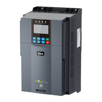
INVT GD390L-5R5G-4-C2 User Manual (226 pages)
Lift-Dedicated VFD
Brand:
INVT
| Category:
Servo Drives
| Size: 15 MB
Table of Contents
Table of Contents
4
Safety Precautions
9
Safety Declaration
9
Safety Level Definition
9
Personnel Requirements
9
Safety Guidelines
10
Product Overview
13
Product Nameplate and Model
13
Product Specifications
13
Product Ratings
15
Product Dimensions and Weight
16
Product Heat Dissipation
16
Structure Diagram
17
System Configuration
18
Mechanical Installation
21
Unpacking Inspection
21
Preparing
21
Installation Environment and Site
22
Installation Direction
23
Installation Space
23
Mounting Method
23
Wall Mounting
23
Remove the Lower Cover
24
Electrical Installation
25
Insulation Inspection
25
Cable Selection and Routing
25
Cable Selection
25
Cable Arrangement
26
Standard Wiring
27
Main Circuit Wiring Diagrams
27
Main Circuit Terminal
27
Wiring Procedure
28
Control Circuit Wiring
30
Control Circuit Wiring Diagram
30
Control Terminal Diagram
31
Input/Output Signal Connection Diagram
32
Power Distribution Protection
33
Keypad Instruction
35
Keypad Introduction
35
Keypad Display
37
Displaying Stopped-State Parameters
37
Displaying Running-State Parameters
37
Displaying Fault Information
38
Editing Function Codes
38
Operation Procedure
39
System Settings of LCD Keypad
39
How to Modify VFD Function Codes
39
How to Set the VFD User Password
40
How to View the Function Parameters
41
Commissioning Guidelines
43
What this Chapter Contains
43
Wiring between the Lift Controller and VFD
44
Wiring for the Multi-Step Speed Running Mode
44
Wiring for the Analog Speed Running Mode
44
Basic Parameter Settings
45
Commissioning Running
46
Motor Parameter Autotuning
46
Adjusting Maintenance Running Parameters
47
Adjusting the S Curve for Normal Running
48
Adjusting Comfortability During Startup or Stop
49
Adjusting Lift Leveling Accuracy
49
Lift Running Mode
50
Multi-Step Speed Mode (Brake and Contactor Are Controlled by the VFD)
50
Analog Speed Tracking Running Mode
57
Maintenance Running
59
Emergency Running
60
Communication Protocol
64
Modbus Protocol
64
Application of Modbus
64
RTU Command Codes and Communication Data
71
Common Communication Faults
86
Canopen Communication Protocol
86
Electrical Connection
86
Communication
88
Process Data Object (PDO)
99
Monitoring Process Data through SDO Commands
108
Baud Rate and Communication Address Setting
111
Common Communication Faults
113
Object Dictionary
113
Troubleshooting
119
Fault Indication and Reset
119
Faults and Solutions
119
Other Status
126
Analysis on Common Faults
127
Motor Fails to Work
127
Motor Vibrates
128
Overvoltage
128
Undervoltage
129
Motor Overheating
129
VFD Overheating
130
Motor Stalls During ACC
130
Overcurrent
131
Inspection and Maintenance
132
Daily Inspection and Regular Maintenance
132
Replacement of Wearing Parts
133
Cooling Fan
133
Electrolytic Capacitor
135
Reforming
135
Appendix A Expansion Card
137
Model Description
137
Dimensions and Installation of the
138
Incremental Encoder
138
Technical Specifications
138
Terminal Interfaces and Switches
139
Wiring
140
Application Connection
141
Sin/Cos Encoder
143
Technical Specifications
143
Terminal Interfaces and Switches
144
Absolute Encoder
145
Technical Specifications
145
Terminal Interfaces and Switches
145
Appendix B Derating
147
Derating Due to Temperature
147
Derating Due to Altitude
147
Derating Due to Carrier Frequency
147
Appendix C Technical Data
148
What this Chapter Contains
148
Grid Specifications
148
Motor Connection Data
148
EMC Compatibility and Motor Cable Length
148
Application Standards
149
CE Marking
149
EMC Compliance Declaration
150
EMC Regulations
150
Appendix D Dimension Drawings
151
VFD Overall Dimensions
151
Appendix E Peripheral Accessories
152
Cable
152
Power Cable
152
Control Cable
153
Breaker and Electromagnetic Contactor
153
Optional Parts
154
Reactor
154
Filter
155
Braking Component
156
Appendix F Function Parameter List
158
Group P00-Basic Functions
158
Group P01-Start and Stop Control
162
Group P02-Parameters of Motor 1
164
Group P03-Vector Control of Motor
167
Group P04-V/F Control
169
Group P05-Input Terminals
174
Group P06-Output Terminals
177
Group P07-HMI
179
Group P08-Enhanced Functions
188
Group P09-PID Control (Reserved)
193
Group P10-Speed Curve Settings
193
Group P11-Protection Parameters
194
Group P12-Parameters of Motor 2 (Reserved)
196
Group P13-SM Control
196
Group P14-Serial Communication
199
Group P15-Communication Expansion Card 1 Functions
203
Group P16-Communication Expansion Card 2 Functions
206
Group P17-Status Viewing
207
Group P18-Status Viewing in Closed-Loop Control
211
Group P19-Expansion Card Status Viewing (Reserved)
212
Group P20-Encoders
212
Group P21-Position Control (Reserved)
215
Group P22-Spindle Positioning (Reserved)
215
Group P23-Vector Control of Motor 2 (Reserved)
215
Group P24-Encoder of Motor 2 (Reserved)
215
Group P25-Expansion I/O Card Input (Reserved)
215
Group P26-Expansion I/O Card Output (Reserved)
215
Group P27-Programmable Expansion Card Functions (Reserved)
215
Group P28-Master/Slave Control (Reserved)
215
Group P90-Deadzone Compensation Identification 1
215
Group P91-Deadzone Compensation Identification 2
216
Group P92-Running Time Reached Function (Reserved)
216
Group P93-Simple Direct Docking Function (Reserved)
217
Group P94-Demonstration Type Direct Docking Function (Reserved)
217
Group P95-Communication Type Direct Docking Function (Reserved)
217
Group P96-Lift Enhanced Function
217
Group P97-Temperature Detection Calibration
219
Group P98-AIAO Calibration Function
220
Appendix G STO Function Codes
222
STO Function Logic Table
222
STO Channel Delay Description
223
STO Function Parameter
223
STO Fault
223
E40 Alarm
224
E41 Fault
224
E42 Fault
225
Advertisement
Advertisement
Related Products
INVT GD390L-5R5G-2
INVT GD390L-5R5G-4
INVT GD390L-2R2G-2
INVT GD390L-7R5G-2
INVT GD390L-004G-4
INVT GD390L-004G-4-C2
INVT GD390L-7R5G-4
INVT GD390L-7R5G-4-C2
INVT GD390L-015G-4-C2
INVT GD390L-004G-2
INVT Categories
Inverter
DC Drives
Servo Drives
Controller
UPS
More INVT Manuals
Login
Sign In
OR
Sign in with Facebook
Sign in with Google
Upload manual
Upload from disk
Upload from URL