Sign In
Upload
Manuals
Brands
IEI Technology Manuals
Single board computers
PCIE-9450
IEI Technology PCIE-9450 Manuals
Manuals and User Guides for IEI Technology PCIE-9450. We have
3
IEI Technology PCIE-9450 manuals available for free PDF download: User Manual, Quick Installation Manual
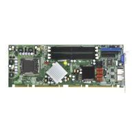
IEI Technology PCIE-9450 User Manual (232 pages)
PICMG 1.3 LGA775 Intel Core 2 Duo, Pentium 4/D VGA, Dual PCIe GbE, SATA II and USB2.0
Brand:
IEI Technology
| Category:
Motherboard
| Size: 9.62 MB
Table of Contents
Table of Contents
6
1 Introduction
21
Overview
22
PCIE-9450 Features
22
Figure 1-1: PCIE-9450 Overview
23
Pcie-9450 Overview
23
PCIE-9450 Overview Photo
23
PCIE-9450 Peripheral Connectors and Jumpers
23
Technical Specifications
25
Table 1-1: Technical Specifications
26
2 Detailed Specifications
27
Dimensions
28
Board Dimensions
28
Figure 2-1: PCIE-9450 Dimensions (MM)
28
Figure 2-2: External Interface Panel Dimensions (MM)
29
Data Flow
30
Overview
28
External Interface Panel Dimensions
29
Figure 2-3: Data Flow Block Diagram
30
Table 2-1: Supported Intel® Core™ 2 Duo Processors
31
Table 2-2: Supported Intel® Pentium® 4 Processors
31
Celeron ® D Processors
31
Compatible Processors
31
CPU Overview
31
Supported Intel® Core™ 2 Duo Processors
31
Supported Intel® Pentium® 4 Processors
31
Intel ® 945G Northbridge Chipset
32
Intel ® 945G Overview
32
Supported Intel® Celeron® D Processors
32
Supported Intel® Pentium® D Processors
32
Table 2-3: Supported Intel® Pentium® D Processors
32
Figure 2-4: 240-Pin DIMM Sockets
33
Table 2-5: Supported HDD Specifications
37
Figure 2-5: Pcie Slot Connector
39
BIOS Chipset
40
Figure 2-6: LPC Bus Chipsets
40
Lpc Bus Components
40
LPC Bus Overview
40
Super I/O 16C550 Uarts
41
Super I/O Chipset
41
Super I/O LPC Interface
41
Super I/O Fan Speed Controller
42
Super I/O Floppy Disk Controller
42
Super I/O Hardware Monitor
42
Super I/O Parallel Port
42
Environmental and Power Specifications
43
System Monitoring
43
Expansion Options
44
Expansion Options Overview
44
Operating Temperature and Temperature Control
44
Power Consumption
44
Table 2-6: Power Consumption
44
IEI Expansion PICMG 1.3 Backplanes
45
IEI Chassis
46
Table 2-4: Supported Intel
32
Intel ® ICH7R Real Time Clock
38
Intel ® ICH7R SATA Controller
38
Intel ® ICH7R USB Controller
38
Pci Bus Components
38
PCI Bus Overview
38
Broadcom Pcie Gbe Interface
39
PCI Express (Pcie) Slot Connector
39
Intel ® 945G Memory Support
33
Intel ® 945G Serial Digital Video Output (SDVO)
33
Intel ® 945G Integrated Graphics Media Accelerator 950
34
Intel ® Ich7R Southbridge Chipset
35
Intel ® ICH7R Overview
35
Intel ® ICH7R Audio Codec '97 Controller
36
Intel ® ICH7R IDE Interface
36
Intel ® ICH7R Low Pin Count (LPC) Interface
37
Intel ® ICH7R PCI Interface
37
Table 2-7: Compatible IEI Backplanes
46
Table 2-8: Compatible IEI Chassis
47
3 Unpacking
49
Anti-Static Precautions
50
Unpacking
50
Unpacking Precautions
50
Unpacking Checklist
51
Package Contents
51
Optional Components
52
Table 3-1: Package List Contents
52
Table 3-2: Optional Components
53
4 Connector Pinouts
55
Figure 4-1: Connector and Jumper Locations
56
Table 4-3: +12V ATX Power Connector Pinouts
59
Figure 4-2: +12V ATX Power Connector Location
59
Figure 4-3: Audio Connector Location (10-Pin)
60
Table 4-4: Audio Connector Pinouts (10-Pin)
60
Fan Connectors
61
Digital Input/Output (DIO) Connector
60
Peripheral Interface Connectors
56
PCIE-9450 Layout
56
Table 4-1: Peripheral Interface Connectors
57
Table 4-2: External Peripheral Interface Panel Connectors
58
Audio Connector (10-Pin)
59
External Peripheral Interface Panel Connectors
58
Internal Peripheral Connectors
58
ATX Power Supply Connector
58
Figure 4-4: DIO Connector Locations
61
Table 4-6: Fan Connectors Pinouts
62
Figure 4-6: 34-Pin FDD Connector Location
63
Figure 4-7: Front Panel Connector Pinout Locations
64
Table 4-7: 34-Pin FDD Connector Pinouts
64
IDE Connector (40-Pin)
65
Table 4-8: Front Panel Connector Pinouts
65
Figure 4-8: IDE Device Connector Locations
66
Figure 4-9: Infrared Connector Pinout Locations
67
Infrared Interface Connector (5-Pin)
67
Keyboard Connector
67
Table 4-10: Infrared Connector Pinouts
67
Table 4-9: IDE Connector Pinouts
67
Figure 4-10: Keyboard Connector Location
68
Parallel Port Connector
68
Table 4-11: Keyboard Connector Pinouts
68
Figure 4-11: Parallel Port Connector Location
69
Figure 4-12: SATA Drive Connector Locations
70
SATA Drive Connectors
70
Table 4-12: Parallel Port Connector Pinouts
70
Figure 4-13: Serial Port Connector Pinout Locations
71
Serial Port Connector (COM1 and COM2)
71
Table 4-13: SATA Drive Connector Pinouts
71
Figure 4-14: USB Connector Pinout Locations
72
Table 4-14: Serial Port Connector Pinouts
72
USB Connectors (Internal)
72
External Peripheral Interface Connectors
73
Figure 4-15: PCIE-9450 External Peripheral Connector Panel
73
Keyboard/Mouse Connector
73
Table 4-15: USB Port Connector Pinouts
73
Ethernet Connector
74
Table 4-5: DIO Connector Pinouts
61
Front Panel Connector (12-Pin)
64
Figure 4-5: Fan Connectors Locations
62
Floppy Disk Connector (34-Pin)
62
Table 4-16: Keyboard Connector Pinouts
74
Table 4-17: Mouse Connector Pinouts
74
Figure 4-17: Ethernet Connector
75
Table 4-18: Ethernet Connector Pinouts
75
Table 4-19: Ethernet Connector Leds
76
Table 4-20: USB Connector Pinouts
76
Figure 4-18: VGA Connector
77
On-Board Jumpers
77
Table 4-21: VGA Connector Pinouts
77
Figure 4-16: PS/2 Pinout and Configuration
74
USB Connectors
76
VGA Connector
76
5 Installation
79
Anti-Static Precautions
80
Installation Considerations
81
Installation Notices
81
Installation Checklist
82
Cpu, Cpu Cooling Kit and DIMM Installation
83
Socket LGA775 CPU Installation
83
Figure 5-1: Intel LGA775
84
Figure 5-2: Remove the CPU Socket Protective Shield
85
Figure 5-3: Open the CPU Socket Load Plate
85
Figure 5-6: Securing the Heat Sink to the PCB Board
88
Figure 5-7: Installing a DIMM
89
Figure 5-8: Jumper
90
Table 5-1: Jumpers
90
Clear CMOS Jumper
91
Table 5-2: Clear CMOS Jumper Settings
91
Airflow
92
Chassis Installation
92
Figure 5-9: Clear CMOS Jumper
92
Backplane Installation
93
CPU Card Installation
93
Internal Peripheral Device Connections
93
Peripheral Device Cables
93
Table 5-3: IEI Provided Cables
93
ATA Flat Cable Connection
94
Figure 5-10: IDE Cable Connection
94
Figure 5-11: Keyboard/Mouse Y-Cable Connection
95
Keyboard/Mouse Y-Cable Connector
95
Figure 5-12: Single RS-232 Cable Installation
97
Single RS-232 Cable Connection
97
Figure 5-13: SATA Drive Cable Connection
98
SATA Drive Connection
98
Figure 5-14: SATA Power Drive Connection
99
USB Cable Connectors
99
Figure 5-15: Dual USB Cable Connection
100
External Peripheral Interface Connection
101
PS/2 y Cable Connection
101
Ethernet Connection
102
Figure 5-16: PS/2 Connector
102
Figure 5-17: RJ-45 Connector
102
USB Connection
103
VGA Monitor Connection
103
Jumper Settings
90
Figure 5-4: Insert the LGA775 CPU
86
Figure 5-5: IEI Cooling Kits
87
LGA775 Cooling Kit Installation
87
DIMM Installation
88
Figure 5-18: USB Connector
103
Figure 5-19: VGA Connector
104
6 Bios Screens
105
Introduction
106
Starting Setup
106
Using Setup
106
Getting Help
107
Unable to Reboot after Configuration Changes
107
BIOS Menu Bar
107
Table 6-1: BIOS Navigation Keys
107
BIOS Menu 1: Main
108
Advanced
109
CPU Configuration
110
Main
108
BIOS Menu 2: Advanced
110
BIOS Menu 3: CPU Configuration
110
IDE Configuration
111
BIOS Menu 4: IDE Configuration
111
IDE Master, IDE Slave
112
BIOS Menu 5: IDE Master and IDE Slave Configuration
113
Floppy Configuration
118
BIOS Menu 6: IDE Master and IDE Slave Configuration
118
Super IO Configuration
119
BIOS Menu 7: Super IO Configuration
119
Hardware Health Configuration
122
BIOS Menu 8: Hardware Health Configuration
122
ACPI Configuration
123
BIOS Menu 9: ACPI Configuration
123
General ACPI Configuration
124
BIOS Menu 10: General ACPI Configuration
124
APM Configuration
125
BIOS Menu 11: Advanced Power Management Configuration
125
Remote Access Configuration
127
BIOS Menu 12: Remote Access Configuration
128
USB Configuration
129
BIOS Menu 13: USB Configuration
129
USB Mass Storage Device Configuration
131
BIOS Menu 14: USB Mass Storage Device Configuration
131
Pci/Pnp
133
BIOS Menu 15: Pci/Pnp Configuration
133
Boot
138
BIOS Menu 16: Boot
138
Boot Settings Configuration
139
BIOS Menu 17: Boot Settings Configuration
139
Boot Device Priority
141
Removable Drives
142
BIOS Menu 18: Boot Device Priority Settings
142
Security
143
BIOS Menu 19: Removable Drives
143
BIOS Menu 20: Security
143
Chipset
144
Northbridge Configuration
145
BIOS Menu 21: Chipset
145
BIOS Menu 22:Northbridge Chipset Configuration
145
Southbridge Chipset Configuration
147
BIOS Menu 23: Southbridge Chipset Configuration
147
Exit
149
BIOS Menu 24:Exit
149
7 Software Drivers
151
Available Software Drivers
152
Driver CD Auto-Run
152
Figure 7-2: Available Drivers
153
Figure 7-1: Introduction Screen
153
Chipset Driver Installation
154
Figure 7-3: Chipset Driver Installation Program
154
Figure 7-4: Chipset Driver Installation Welcome Screen
154
Figure 7-6: Chipset Driver Readme File Information
155
Figure 7-5: Chipset Driver Installation License Agreement
155
Figure 7-7: Chipset Driver Installation Complete
156
Figure 7-32: SATA RAID Setup Program Icon
173
Figure 7-33: Installshield Wizard Setup Screen
174
Figure 7-34: Matrix Storage Manager Setup Screen
175
Figure 7-36: Matrix Storage Manager Warning Screen
176
Figure 7-35: Matrix Storage Manager Welcome Screen
176
Figure 7-37: Matrix Storage Manager License Agreement
177
Figure 7-38: Matrix Storage Manager Readme File
178
Figure 7-39: Matrix Storage Manager Setup Complete
179
Figure 7-40: Access Windows Control Panel
180
Ide Controller Installation
180
Intel Graphics Media Accelerator Driver
156
Figure 7-8: Select the Operating System
157
Figure 7-9: VGA Driver
157
Figure 7-10: Intel® Graphics Media Accelerator Installshield Wizard
158
Figure 7-11: Installshield Wizard Extracting Files
158
Figure 7-16: Windows Control Panel
161
Figure 7-17: System Icon
162
Figure 7-18: Device Manager Tab
163
Figure 7-19: Device Manager List
164
Figure 7-20: Search for Suitable Driver
165
Figure 7-22: Location Browsing Window
166
Figure 7-23: Select the Audio CODEC
167
Figure 7-24: Locate the Setup Program Icon
168
Figure 7-26: Installshield Wizard Welcome Screen
169
Figure 7-27: Audio Driver Software Configuration
169
Figure 7-28: Audio Driver Digital Signal
170
Figure 7-29: Audio Driver Installation
170
Figure 7-30: Restart the Computer
171
Figure 7-31: SATA RAID Driver Installation Program
172
Sata Raid Driver
172
Figure 7-21: Locate Driver Files
165
Realtek Ac`97 Audio Driver (Alc665) Installation
166
BIOS Setup
166
Driver Installation
166
Figure 7-25: Preparing Setup Screen
168
Realtek Hd Audio Driver (Alc883) Installation
171
BIOS Setup
171
Driver Installation
171
Figure 7-12: Intel® Graphics Media Accelerator Driver Welcome Screen
159
Figure 7-13: Intel® Graphics Media Accelerator Driver License Agreement
159
Figure 7-14: Intel® Graphics Media Accelerator Driver Installing Notice
160
Figure 7-15: Intel® Graphics Media Accelerator Installation Complete
160
Broadcom LAN Driver (for Gbe LAN) Installation
161
Figure 7-41: Double Click the System Icon
181
Figure 7-42: Double Click the Device Manager Tab
182
Figure 7-43: Device Manager List
183
Figure 7-44: Search for Suitable Driver
184
Figure 7-45: Locate Driver Files
184
Figure 7-46: Location Browsing Window
185
Abios Options
187
Bdio Interface
191
Dio Interface Introduction
192
Dio Connector Pinouts
192
Assembly Language Samples
193
Enable the DIO Input Function
193
Enable the DIO Output Function
193
Cwatchdog Timer
195
Daddress Mapping
199
Address Map
200
St Mb Memory Ddress Ap
200
Irq Mapping Table
201
Dma Channel Assignments
201
Matrix Storage Manager
203
Introduction
204
Precautions
204
Features and Benefits
205
Accessing the Intel Matrix Storage Manager
205
Raid Configuration
206
Creating a RAID Volume
206
Deleting a RAID Volume
211
Resetting a Disk to Non-RAID
213
Exiting the Matrix Storage Manager
215
Fexternal Ac'97 Audio Codec
217
Introduction
218
Accessing the AC'97 CODEC
218
Driver Installation
218
Sound Effect Configuration
219
Accessing the Sound Effects Manager
219
Sound Effect Manager Configuration Options
220
Hazardous Materials Disclosure
223
Hazardous Material Disclosure Table for IPB Products Certified as Rohs Compliant under 2002/95/EC Without Mercury
224
Hindex
227
Advertisement
IEI Technology PCIE-9450 Quick Installation Manual (8 pages)
PICMG 1.3 LGA 775 Intel Core 2 Duo Pentium D/4 CPU Card with VGA, Dual PCIe GbE and SATAII
Brand:
IEI Technology
| Category:
Motherboard
| Size: 0.17 MB
IEI Technology PCIE-9450 Quick Installation Manual (3 pages)
Intel Processor LGA775 Pentium D PICMG1.3 Full-Size CPU Card with PCIE-GbE, SATA II RAID, and USB2.0
Brand:
IEI Technology
| Category:
Single board computers
| Size: 0.13 MB
Advertisement
Advertisement
Related Products
IEI Technology PCIE-690S1
IEI Technology PCIE-690AM2
IEI Technology PCISA-6770 Series
IEI Technology PICOe-945GSE
IEI Technology PM-BT series
IEI Technology PM-BT-N28071
IEI Technology PM-BT-E38451W2
IEI Technology PSC-586VGA
IEI Technology PM-PV-N4551/D5251
IEI Technology PSB-810EAV
IEI Technology Categories
Motherboard
Touch Panel
Computer Hardware
Single board computers
Desktop
More IEI Technology Manuals
Login
Sign In
OR
Sign in with Facebook
Sign in with Google
Upload manual
Upload from disk
Upload from URL