Sign In
Upload
Manuals
Brands
IEI Technology Manuals
Single board computers
PM-PV-N4551/D5251
IEI Technology PM-PV-N4551/D5251 Manuals
Manuals and User Guides for IEI Technology PM-PV-N4551/D5251. We have
1
IEI Technology PM-PV-N4551/D5251 manual available for free PDF download: User Manual
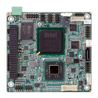
IEI Technology PM-PV-N4551/D5251 User Manual (115 pages)
PCI-104 with Intel Atom Processor N455/D525 Ethernet, USB, CompactFlash, RoHS Compliant
Brand:
IEI Technology
| Category:
Single board computers
| Size: 3.28 MB
Table of Contents
Table of Contents
5
Introduction
13
Introduction
14
Applications
14
Benefits
14
Figure 1-1: PM-PV-N4551/D5251
14
Features
15
Overview
16
Figure 1-2: Overview
16
Figure 1-3: Solder Side Overview
16
Connectors
17
Dimensions
18
Figure 1-4: Dimensions (Top)
18
Figure 1-5: Dimensions (I/O)
18
Figure 1-6: Dimensions (Bottom)
19
Data Flow
20
Figure 1-7: Data Flow Block Diagram
20
Technical Specifications
21
Table 1-1: Technical Specifications
22
Unpacking
23
Anti-Static Precautions
24
Unpacking Precautions
24
Packing List
25
Optional Items
26
Table 2-1: Package List Contents
26
Table 2-2: Optional Packing List Items
26
Connectors
27
Peripheral Interface Connectors
28
Layout
28
Figure 3-1: Connector and Jumper Locations (Front Side)
28
Figure 3-2: Connector and Jumper Locations (Solder Side)
28
Peripheral Interface Connectors
29
Table 3-1: Internal Peripheral Connectors
29
Internal Peripheral Connectors
30
ATX Power Control Connector
30
Figure 3-3: ATX Power Supply Enable Connector Location
30
Table 3-2: ATX Power Supply Enable Connector Pinouts
30
Audio Kit Connector
31
Compactflash® Slot
31
Figure 3-4: Audio Kit Connector Location
31
Table 3-3: Audio Kit Connector Pinouts
31
Figure 3-5: Compactflash® Slot Location
32
Digital I/O Connector
33
Figure 3-6: Digital I/O Connector Locations
33
Table 3-4: Compactflash® Slot Pinouts
33
Fan Connector
34
Figure 3-7: Fan Connector Location
34
Table 3-5: Digital I/O Connector Pinouts
34
Table 3-6: Fan Connector Pinouts
34
Front Panel Connector
35
Figure 3-8: Front Panel Connector Location
35
Table 3-7: Front Panel Connector Pinouts
35
Keyboard/Mouse Connector
36
Figure 3-9: Keyboard/Mouse Connector Location
36
Table 3-8: Keyboard/Mouse Connector Pinouts
36
LAN Connector
37
Figure 3-10: LAN Connector Location
37
Table 3-9: LAN Connector Pinouts
37
LVDS LCD Connector
38
Figure 3-11: LVDS Connector Location
38
Table 3-10: LVDS Connector Pinouts
38
LVDS Backlight Inverter Connector
39
Connector
39
Figure 3-12: Backlight Inverter Connector Location
39
Table 3-11: Backlight Inverter Connector Pinouts
39
Figure 3-13: PCI-104 Connector Location
40
Power Connector
41
Figure 3-14: Power Connector Location
41
Table 3-12: PCI-104 Connector Pinouts
41
SATA Drive Connectors
42
Figure 3-15: SATA Drive Connector Location
42
Table 3-13: Power Connector Pinouts
42
Table 3-14: SATA Drive Connector Pinouts
42
Serial Port Connector (RS-232)
43
Figure 3-16: Serial Port Connector Location (COM1)
43
Table 3-15: Serial Port Connector Pinouts (COM1)
43
Serial Port Connector (RS-232/422/485)
44
Figure 3-17: Serial Port Connector Location (COM2)
44
Table 3-16: Serial Port Connector Pinouts (COM2)
44
USB Connector
45
VGA Connector
45
Figure 3-18: USB Connector Pinout Locations
45
Table 3-17: USB Port Connector Pinouts
45
Figure 3-19: VGA Connector Location
46
Table 3-18: VGA Connector Pinouts
46
Installation
47
Anti-Static Precautions
48
Installation Considerations
49
Installation Notices
49
Installation Checklist
50
Unpacking
51
So-DIMM Installation
52
Compactflash® Card Installation
52
Figure 4-1: SO-DIMM Installation
52
Jumper Settings
53
Figure 4-2: Compactflash® Card Installation
53
AT/ATX Power Mode Jumper
54
Table 4-1: Jumper Settings
54
Table 4-2: AT/ATX Power Mode Jumper Settings
54
Clear CMOS Jumper
55
Figure 4-3: AT/ATX Power Mode Jumper Location
55
Figure 4-4: Clear BIOS Jumper Location
55
Table 4-3: Clear BIOS Jumper Settings
55
Compactflash® Setup
56
LVDS Voltage Selection
56
Figure 4-5: Compactflash® Setup Jumper Location
56
Table 4-4: Compactflash® Setup Jumper Settings
56
Voltage Setup
57
Figure 4-6: LVDS Voltage Selection Jumper Locations
57
Table 4-5: LVDS Voltage Selection Jumper Settings
57
COM 2 Function Select Jumper
58
Figure 4-7: PCI-104 Voltage Jumper Location
58
Table 4-6: PCI-104 Voltage Jumper Settings
58
Table 4-7: COM 2 Function Select Jumper Settings
58
Chassis Installation
59
Figure 4-8: COM 2 Function Select Jumper Location
59
Internal Peripheral Device Connections
60
Keyboard/Mouse Y-Cable Connector
60
LVDS LCD Installation
61
Figure 4-9: Keyboard/Mouse Y-Cable Connection
61
Figure 4-10: LVDS Connector
62
SATA Drive Connection
63
Figure 4-11: Backlight Inverter Connection
63
Figure 4-12: SATA Drive Cable Connection
64
Figure 4-13: SATA Power Drive Connection
64
USB Cable
65
Figure 4-14: Dual USB Cable Connection
65
Software Installation
66
Figure 4-15: Introduction Screen
66
Figure 4-16: Available Drivers
67
Bios
68
Introduction
69
Starting Setup
69
Using Setup
69
Getting Help
70
Unable to Reboot after Configuration Changes
70
BIOS Menu Bar
70
Table 5-1: BIOS Navigation Keys
70
Main
71
BIOS Menu 1: Main
71
Advanced
72
ACPI Settings
72
BIOS Menu 2: Advanced
72
CPU Configuration
73
BIOS Menu 3: ACPI Settings
73
BIOS Menu 4: CPU Configuration
74
SATA Configuration
75
BIOS Menu 5: IDE Configuration
75
USB Configuration
76
BIOS Menu 6: USB Configuration
76
Super IO Configuration
77
BIOS Menu 7: Super IO Configuration
77
Serial Port N Configuration
78
BIOS Menu 8: Serial Port N Configuration Menu
78
H/W Monitor
81
BIOS Menu 9: Hardware Health Configuration
81
Serial Port Console Redirection
84
BIOS Menu 10: Serial Port Console Redirection
84
Chipset
85
BIOS Menu 11: Chipset
85
Host Bridge Configuration
86
BIOS Menu 12: Host Bridge Chipset Configuration
86
Onchip VGA Configuration
87
BIOS Menu 13: Onchip VGA Configuration
87
South Bridge Configuration
88
BIOS Menu 14:South Bridge Chipset Configuration
88
Intel IGD SWSCI Opregion
89
BIOS Menu 15:South Bridge Chipset Configuration
90
Boot
91
BIOS Menu 16: Boot
91
Security
92
BIOS Menu 17: Security
93
Exit
94
BIOS Menu 18:Exit
94
A Regulatory Compliance
96
B Product Disposal
98
C Bios Options
100
D Terminology
103
E Digital I/O Interface
107
Introduction
108
Assembly Language Sample 1
109
Assembly Language Sample 2
109
F Watchdog Timer
110
G Hazardous Materials Disclosure
113
Advertisement
Advertisement
Related Products
IEI Technology PM-BT series
IEI Technology PM-BT-J19001
IEI Technology PM-BT-N28071
IEI Technology PM-BT-E38451W2
IEI Technology PM-BT-E38251W2
IEI Technology PICOe-945GSE
IEI Technology PCIE-690S1
IEI Technology PSB-810EAV
IEI Technology PCIE-690AM2
IEI Technology PSC-586VGA
IEI Technology Categories
Motherboard
Touch Panel
Computer Hardware
Single board computers
Desktop
More IEI Technology Manuals
Login
Sign In
OR
Sign in with Facebook
Sign in with Google
Upload manual
Upload from disk
Upload from URL