Sign In
Upload
Manuals
Brands
IEI Technology Manuals
Single board computers
PICOe-945GSE
IEI Technology PICOe-945GSE Manuals
Manuals and User Guides for IEI Technology PICOe-945GSE. We have
1
IEI Technology PICOe-945GSE manual available for free PDF download: User Manual
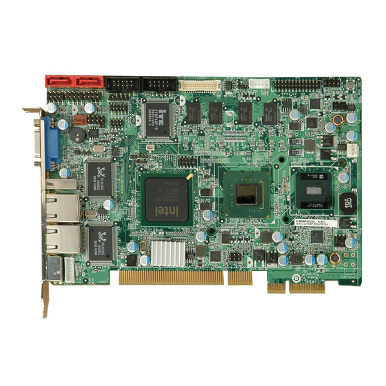
IEI Technology PICOe-945GSE User Manual (203 pages)
Half-Size PCIe CPU Card with Intel Atom Processor, 512 MB On-Board Memory, VGA/LVDS/HDTV-out Dual GbE, Seven USB 2.0, CF Slot and Two SATA
Brand:
IEI Technology
| Category:
Single board computers
| Size: 11.26 MB
Table of Contents
Table of Contents
7
List of Figures
13
Introduction
19
Overview
20
Picoe-945GSE Introduction
20
Picoe-945GSE Overview
21
Figure 1-2: Picoe-945GSE Overview [Front View]
21
Picoe-945GSE Overview Photo
21
Figure 1-3: Picoe-945GSE Overview [Solder Side]
22
Picoe-945GSE Peripheral Connectors and Jumpers
22
Technical Specifications
23
Detailed Specifications
26
Dimensions
27
Board Dimensions
27
Figure 2-1: Picoe-945GSE Dimensions (MM)
27
External Interface Panel Dimensions
28
Data Flow
28
F Igure 2-2: External Interface Panel Dimensions
28
Embedded Picoe-945GSE Processor
29
Figure 2-3: Data Flow Block Diagram
29
Overview
29
Features
30
Figure 2-4: Embedded Processor
30
Figure 2-5: Front Side Bus
31
Front Side Bus (FSB)
31
Intel 945Gse Northbridge Chipset
32
DDR2 SO-DIMM Socket
32
Figure 2-6: On-Board DDR2 SDRAM Chips
32
Intel® 945GSE DDR2 Controller
32
Intel® 945GSE Overview
32
On-Board DDR2 SDRAM
32
Figure 2-7: DDR2 SO-DIMM Socket
33
Intel® 945GSE Graphics
33
Analog CRT Graphics Mode
34
LVDS Interface
34
Serial Digital Video Output (SDVO)
35
TV out Interface
35
Intel ® Ich7-M Southbridge Chipset
36
Intel ® ICH7-M Audio Controllers
36
Intel ® ICH7-M Overview
36
Intel ICH7-M Audio Codec '97 Controller
37
Figure 2-9: PCI Golden Finger
38
Pci Gbe Controllers
38
Figure 2-10: RJ-45 Connectors and Gbe Controllers
39
Figure 2-11: Pcie X4 Golden Finger
40
Figure 2-12: SATA Connectors
41
Figure 2-13: Onboard USB Implementation
42
Lpc Bus Overview
42
Ite It8718F Super I/O Chipset
43
Super I/O 16C550 Uarts
44
Super I/O Digital Input/Output
44
Super I/O Enhanced Hardware Monitor
44
Super I/O Fan Speed Controller
44
Super I/O Keyboard/Mouse Controller
44
Super I/O Lpc Interface
44
Operating Temperature and Temperature Control
46
Table 2-1: Power Consumption
46
Optional Items
50
Figure 4-1: Connector and Jumper Locations [Front Side]
52
Figure 4-2: Connector and Jumper Locations [Solder Side]
53
T Able 4-1: Peripheral Interface Connectors
53
Table 4-2: Rear Panel Connectors
54
External Interface Panel Connectors
54
Figure 4-3: ATX Power Supply Enable Connector Location
55
Table 4-3: ATX Power Supply Enable Connector Pinouts
55
Figure 4-4: Audio Connector Location (9-Pin)
56
Table 4-4: Audio Connector Pinouts (9-Pin)
56
Figure 4-5: Panel Backlight Connector Pinout Locations
57
Table 4-5: Panel Backlight Connector Pinouts
57
Backlight Inverter Connector
57
F Igure 1-1: Picoe-945GSE
58
Figure 4-6: CF Card Socket Location
58
Compactflash® Socket
58
Table 4-6: CF Card Socket Pinouts
59
Digital Input/Output (Dio) Connector
59
Figure 4-7: DIO Connector Connector Locations
60
Table 4-7: DIO Connector Connector Pinouts
60
Fan Connector (+12V, 3-Pin)
60
Figure 4-8: +12V Fan Connector Location
61
Table 4-8: +12V Fan Connector Pinouts
61
Front Panel Connector (8-Pin)
61
Figure 4-9: Front Panel Connector Pinout Locations (8-Pin)
62
Table 4-9: Front Panel Connector Pinouts (8-Pin)
62
Infrared Interface Connector
62
Figure 4-10: Infrared Connector Pinout Locations
63
Table 4-10: Infrared Connector Pinouts
63
Figure 4-11: Keyboard/Mouse Connector Location
64
Table 4-11: Keyboard/Mouse Connector Pinouts
64
Lvds Lcd Connector
64
Figure 4-12: LVDS LCD Connector Pinout Location
65
Table 4-12: LVDS LCD Port Connector Pinouts
65
Figure 4-13: Parallel Port Connector Location
66
Figure 4-14: SATA Drive Connector Locations
67
Table 4-13: Parallel Port Connector Pinouts
67
Sata Drive Connectors
67
Figure 4-15: COM Connector Pinout Locations
68
Table 4-14: SATA Drive Connector Pinouts
68
Serial Port Connectors (Com 1 and Com)
68
Table 4-15: COM Connector Pinouts
69
Sdvo Connector
69
Figure 4-16: SDVO Connector Pinout Locations
70
Table 4-16: SDVO Connector Pinouts
71
Tv out Connector
71
Figure 4-17: TV Connector Pinout Locations
72
Table 4-17: TV Port Connector Pinouts
72
Usb Connectors (Internal)
72
Figure 4-18: USB Connector Pinout Locations
73
Table 4-18: USB Port Connector Pinouts
73
Figure 4-19: Picoe-945GSE External Peripheral Interface Connector
74
Figure 4-20: PS/2 Pinout and Configuration
74
Table 4-19: Keyboard Connector Pinouts
74
Figure 4-21: RJ-45 Ethernet Connector
75
Table 4-20: LAN Pinouts
75
Lan Connectors
75
Table 4-21: RJ-45 Ethernet Connector Leds
76
Table 4-22: USB Port Pinouts
76
Usb Connectors
76
Vga Connector
76
F Igure 2-8: VGA Connector
77
Table 4-23: VGA Connector Pinouts
77
Installation Notices
80
Installation Checklist
81
Figure 5-1: SO-DIMM Installation
82
Cf Card Installation
83
Figure 5-2: CF Card Installation
84
Figure 5-3: Jumper Locations
84
Jumper Settings
84
Table 5-1: Jumpers
85
T Able 5-2: at Power Select Jumper Settings
85
Figure 5-4: at Power Select Jumper Location
86
Table 5-3: CF Card Setup Jumper Settings
86
Figure 5-5: CF Card Setup Jumper Location
87
Clear Cmos Jumper
87
Figure 5-6: Clear CMOS Jumper
88
Lvds Panel Resolution Jumper
88
Table 5-4: Clear CMOS Jumper Settings
88
Figure 5-7: LVDS Panel Resolution Jumper Pinout Locations
89
Table 5-5: LVDS Panel Resolution Jumper Settings
89
Table 5-6: LVDS Voltage Selection Jumper Settings
90
Figure 5-8: LVDS Voltage Selection Jumper Pinout Locations
91
Table 5-7: Pcie Status Select Jumper Settings
91
Backplane Installation
92
Figure 5-9: Pcie Status Select Jumper Pinout Locations
92
Cpu Card Installation
93
Peripheral Device Cables
93
Table 5-8: IEI Provided Cables
93
Figure 5-11: 7.1 Channel Audio Kit
96
Sata Drive Connection
97
Figure 5-12: SATA Drive Cable Connection
98
Figure 5-13: SATA Power Drive Connection
99
Usb Cable (Dual Port) with Slot Bracket
99
Figure 5-14: Dual USB Cable Connection
100
Parallel Port Cable Without Bracket
100
Figure 5-15: LPT Cable Connection
101
Dual Rs-232 Cable with Slot Bracket
102
Figure 5-16: Connect the LPT Device
102
Figure 5-17: Dual RS-232 Cable Installation
103
Figure 5-18: LAN Connection
104
Ps/2 Y-Cable Connection
104
Figure 5-19: PS/2 Keyboard/Mouse Connector
105
Usb Connection (Dual Connector)
105
Figure 5-20: USB Connector
106
Vga Monitor Connection
106
Figure 5-21: VGA Connector
107
Bios Screens
108
Starting Setup
109
Using Setup
109
Table 6-1: BIOS Navigation Keys
110
Getting Help
110
Unable to Reboot after Configuration Changes
110
Bios Menu Bar
110
Ide Configuration
114
Ide Master, Ide Slave
116
Software Drivers
152
Figure 7-1: Start up Screen
154
Figure 7-2: Select Operating System
154
Figure 7-3: Drivers
155
Figure 7-4: Chipset Driver Screen
156
Figure 7-5: Chipset Driver Welcome Screen
156
Figure 7-6: Chipset Driver License Agreement
157
Figure 7-7: Chipset Driver Read Me File
158
Figure 7-8: Chipset Driver Setup Operations
159
Figure 7-9: Chipset Driver Installation Finish Screen
160
Vga Driver Installation
160
Figure 7-10: VGA Driver Read Me File
161
Figure 7-11: VGA Driver Setup Files Extracted
161
Figure 7-12: VGA Driver Welcome Screen
162
Figure 7-13: VGA Driver License Agreement
163
Figure 7-14: VGA Driver Read Me File
163
Figure 7-15: VGA Driver Setup Operations
164
Figure 7-16: VGA Driver Installation Finish Screen
164
Figure 7-17: LAN Driver Welcome Screen
165
Figure 7-18: LAN Driver Welcome Screen
166
Figure 7-19: LAN Driver Installation
166
Figure 7-20: LAN Driver Installation Complete
167
Figure 7-21: Audio Driver Options
168
Figure 7-22: Extract HD Audio Driver Installation Files
169
Figure 7-23: HD Audio Driver Welcome Screen
170
Figure 7-24: System Update
171
Figure 7-25: AC'97 Driver Installation File Extraction
172
Figure 7-26: AC'97 Driver Installation Welcome Screen
172
Figure 7-27: AC'97 Driver Installation Verification
173
Figure 7-28: AC'97 Driver Installation
173
Figure 7-29: AC'97 Driver Installation Complete
174
Watchdog Timer
187
F Igure 2-14: Super I
203
F Igure 4-22: VGA Connector
203
T Able 1-1: Technical Specifications
203
Advertisement
Advertisement
Related Products
IEI Technology PM-BT series
IEI Technology PM-BT-J19001
IEI Technology PM-BT-N28071
IEI Technology PM-BT-E38451W2
IEI Technology PM-BT-E38251W2
IEI Technology PCIE-690S1
IEI Technology PCIE-9450
IEI Technology PSB-810EAV
IEI Technology PCIE-690AM2
IEI Technology PCISA-6770 Series
IEI Technology Categories
Motherboard
Touch Panel
Computer Hardware
Single board computers
Desktop
More IEI Technology Manuals
Login
Sign In
OR
Sign in with Facebook
Sign in with Google
Upload manual
Upload from disk
Upload from URL