Sign In
Upload
Manuals
Brands
IEI Technology Manuals
Single board computers
PM-BT-E38451W2
IEI Technology PM-BT-E38451W2 Manuals
Manuals and User Guides for IEI Technology PM-BT-E38451W2. We have
1
IEI Technology PM-BT-E38451W2 manual available for free PDF download: User Manual
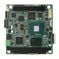
IEI Technology PM-BT-E38451W2 User Manual (108 pages)
PC/104-Plus SBC with Intel Celeron/Atom On-board SoC, DDRL, VGA, LVDS, GbE, USB 2.0, SATA 3Gb/s, RS-232/422/485, 5 V DC Input and RoHS
Brand:
IEI Technology
| Category:
Single board computers
| Size: 2.97 MB
Table of Contents
Table of Contents
5
1 Introduction
13
Introduction
14
Model Variations
14
Figure 1-1: PM-BT
14
Table 1-1: Model Variations
14
Features
15
Connectors
16
Figure 1-2: Connectors
16
Dimensions
17
Figure 1-3: PM-BT Dimensions (MM)
17
Data Flow
18
Figure 1-4: Data Flow Diagram
18
Technical Specifications
19
Table 1-2: PM-BT Specifications
20
2 Packing List
22
Anti-Static Precautions
23
Unpacking Precautions
23
Packing List
24
Optional Items
25
Table 2-1: Packing List
25
Table 2-2: Optional Items
25
3 Connectors
26
Peripheral Interface Connectors
27
PM-BT Layout
27
Figure 3-1: Peripheral Interface Connectors (Front Side)
27
Figure 3-2: Peripheral Interface Connectors (Solder Side)
27
Peripheral Interface Connectors
28
Table 3-1: Peripheral Interface Connectors
28
Internal Peripheral Connectors
29
Battery Connector
29
Buzzer Connector
30
Figure 3-3: Battery Connector Location
30
Table 3-2: Battery Connector Pinouts
30
DDR3L SO-DIMM Socket
31
Figure 3-4: Buzzer Connector Location
31
Figure 3-5: DDR3L SO-DIMM Socket Locations
31
Table 3-3: Buzzer Connector Pinouts
31
Digital I/O Connector
32
Figure 3-6: Digital I/O Connector Location
32
Table 3-4: Digital I/O Connector Pinouts
32
Front Panel Connector
33
Figure 3-7: Front Panel Connector Location
33
Table 3-5: Front Panel Connector Pinouts
33
LAN Connector
34
Figure 3-8: LAN Connector Location
34
Figure 3-9: LAN Cable
34
Table 3-6: LAN Connector Pinouts
34
LVDS LCD Connector
35
Figure 3-10: LVDS Connector Location
35
Table 3-7: LVDS Connector Pinouts
35
LVDS Backlight Inverter Connector
36
Figure 3-11: Backlight Inverter Connector Location
36
Table 3-8: Backlight Inverter Connector Pinouts
36
PC/104-Plus Connector, ISA
37
Figure 3-12: PC/104 Slot Location
37
PC/104-Plus Connector, PCI
38
Table 3-9: PC/104 Slot Connector Pinouts
38
Figure 3-13: PCI-104 Connector Location
39
PC/104-Plus Power Connector
40
Figure 3-14: PC/104-Plus Power Connector Pinouts
40
Table 3-10: PCI-104 Connector Pinouts
40
Pcie Mini Slot
41
Figure 3-15: Pcie Mini Slot Location
41
Table 3-11: PC/104-Plus Power Connector Pinouts
41
Table 3-12: Pcie Mini Slot Pinouts
42
Power Input Connector
43
Figure 3-16: Power Connector Location
43
Table 3-13: Power Connector Pinouts
43
RS-232/422/485 Serial Port Connectors
44
Figure 3-17: RS-232/422/485 Serial Port Connector Locations
44
Table 3-14: RS-232 Serial Port Connector Pinouts
44
Table 3-15: DB-9 RS-232/422/485 Pinouts
45
SATA 3Gb/S Drive Connector
46
Figure 3-18: SATA 3Gb/S Drive Connector Location
46
Table 3-16: SATA 3Gb/S Drive Connector Pinouts
46
SATA Power Connector
47
Figure 3-19: SATA Power Connector Location
47
Table 3-17: SATA Power Connector Pinouts
47
SPI Flash Connector
48
Figure 3-20: SPI Flash Connector Location
48
Table 3-18: SPI Flash Connector Pinouts
48
USB 2.0 Connectors
49
Figure 3-21: USB 2.0 Connector Locations
49
Table 3-19: USB 2.0 Connector Pinouts
49
VGA Connector
50
Figure 3-22: VGA Connector Location
50
Figure 3-23: VGA Cable
50
Table 3-20: VGA Connector Pinouts
50
4 Installation
51
Anti-Static Precautions
52
Installation Considerations
52
So-DIMM Installation
54
Figure 4-1: SO-DIMM Installation
54
Full-Size Pcie Mini Card Installation
55
Figure 4-2: Removing the Retention Screw
55
Figure 4-3: Inserting the Full-Size Pcie Mini Card into the Slot at an Angle
55
System Configuration
56
AT/ATX Power Mode Setting
56
Figure 4-4: Securing the Full-Size Pcie Mini Card
56
Figure 4-5: AT/ATX Power Mode Switch Location
56
LVDS Panel Resolution Select Switch
57
Figure 4-6: LVDS Panel Resolution Select Switch Location
57
Table 4-1: AT/ATX Power Mode Switch Settings
57
Table 4-2: LVDS Panel Resolution Selection
57
LVDS Voltage Selection
58
Figure 4-7: LVDS Voltage Selection Jumper Locations
58
Table 4-3: LVDS Voltage Selection Jumper Settings
58
PCI Voltage Setup
59
Figure 4-8: PCI Voltage Jumper Location
59
Table 4-4: PCI Voltage Jumper Settings
59
Available Drivers
60
Driver Download
60
Figure 4-9: IEI Resource Download Center
60
Os Installation
62
Figure 4-10: BIOS Option-OS Selection
62
5 Bios
63
Introduction
64
Starting Setup
64
Using Setup
64
Getting Help
65
Unable to Reboot after Configuration Changes
65
BIOS Menu Bar
65
Table 5-1: BIOS Navigation Keys
65
Main
66
BIOS Menu 1: Main
66
Advanced
67
BIOS Menu 2: Advanced
67
Trusted Computing
68
BIOS Menu 3: Trusted Computing
68
ACPI Settings
69
BIOS Menu 4: ACPI Configuration
69
F81866 Super IO Configuration
70
Serial Port N Configuration
70
BIOS Menu 5: F81866 Super IO Configuration
70
BIOS Menu 6: Serial Port N Configuration Menu
70
F81866 H/W Monitor
73
BIOS Menu 7: F81866 H/W Monitor
73
RTC Wake Settings
74
BIOS Menu 8: RTC Wake Settings
74
Serial Port Console Redirection
75
BIOS Menu 9: Serial Port Console Redirection
75
Iei Feature
78
BIOS Menu 10: Iei Feature
78
CPU Configuration
79
BIOS Menu 11: CPU Configuration
79
IDE Configuration
80
BIOS Menu 12: IDE Configuration
80
USB Configuration
81
BIOS Menu 13: USB Configuration
81
Chipset
82
North Bridge
83
BIOS Menu 14: Chipset
83
BIOS Menu 15: North Bridge
83
Intel IGD Configuration
84
BIOS Menu 16: Intel IGD Configuration
84
South Bridge
86
BIOS Menu 17: South Bridge
86
PCI Express Configuration
87
BIOS Menu 18: PCI Express Configuration
87
Security
88
BIOS Menu 19: Security
88
Boot
89
BIOS Menu 20: Boot
89
Save & Exit
91
BIOS Menu 21: Save & Exit
91
A Regulatory Compliance
93
B Product Disposal
95
C Bios Options
97
D Digital I/O Interface
100
Introduction
101
Assembly Language Sample 1
102
Assembly Language Sample 2
102
E Watchdog Timer
103
F Hazardous Materials Disclosure
106
Advertisement
Advertisement
Related Products
IEI Technology PM-BT-E38251W2
IEI Technology PM-BT series
IEI Technology PM-BT-J19001
IEI Technology PM-BT-N28071
IEI Technology PM-PV-N4551/D5251
IEI Technology PICOe-945GSE
IEI Technology PCIE-9450
IEI Technology PCIE-690AM2
IEI Technology PSC-586VGA
IEI Technology PCISA-6770 Series
IEI Technology Categories
Motherboard
Touch Panel
Computer Hardware
Single board computers
Desktop
More IEI Technology Manuals
Login
Sign In
OR
Sign in with Facebook
Sign in with Google
Upload manual
Upload from disk
Upload from URL