Sign In
Upload
Manuals
Brands
GE Manuals
Computer Hardware
90-30 PLC
GE 90-30 PLC Manuals
Manuals and User Guides for GE 90-30 PLC. We have
2
GE 90-30 PLC manuals available for free PDF download: Installation And Hardware Manual, User Manual
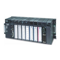
GE 90-30 PLC Installation And Hardware Manual (447 pages)
Brand:
GE
| Category:
Controller
| Size: 5.24 MB
Table of Contents
9
Section 1
9
Table of Contents
16
Section 2
32
Chapter 1 Overview of the Series 90-30 PLC
32
The Basic Parts of a Series 90-30 PLC
33
Assembling a Basic Series 90-30 PLC System
37
What else Would be Needed to Make this Basic System Functional
37
What if the Application Requires more than Five Modules
38
What if the Application Requires more than Ten Modules
39
What Is the Difference between Expansion and Remote Baseplates
40
What if I Need to Cover more than 700 Feet (213 Meters)
41
Chapter 2 Installation
41
Receiving Your Products - Visual Inspection
41
Pre-Installation Check
41
Warranty Claims
42
Working with Series 90-30 Modules
42
Module Features
43
Installing a Module
44
Removing a Module
45
Installing a Module's Terminal Board
46
Removing a Module's Terminal Board
47
I/O Module Terminal Board Posts
47
Installing and Removing Terminal Boards with Holding Screws
48
Baseplate Mounting
48
Mounting a Baseplate to a Panel
48
Mounting a Baseplate to a 19" Rack
51
Grounding Procedures
51
System Grounding Procedures
51
Ground Conductors
52
Series 90-30 PLC Equipment Grounding
52
Baseplate Safety Grounding
53
Grounding 19" Rack-Mounted Baseplates
53
Programmer Grounding
54
Module Shield Grounding
54
Shield Grounding Information for Cpus with External Port Connections
54
CPU351 and 352 Shield Grounding
56
CPU363, CPU364, and CPU374 Shield Grounding
56
Additional Modules with Shield Grounding Requirements
57
General Wiring Guidelines
58
Discrete I/O Module Connection Methods
58
Connections to I/O Module Terminal Boards
59
Terminal Block Quick Connect Installation for 16-Point Discrete Modules
59
Installation of 32-Point Discrete, 50-Pin Connector Modules
59
Using Weidmuller #912263 Terminal Block
60
Using a Generic Terminal Block or Strip
60
Direct Method
60
Installation of Discrete 32-Point, Dual 24-Pin Connector Modules
60
Using a TBQC
60
With a Generic Terminal Block/Strip
61
Direct Method
61
General Wiring Methods for Analog Modules
61
Analog Input Module Wiring Methods
61
Using a Generic Terminal Block or Strip
62
TBQC Not Recommended for Analog Modules
62
Analog Output Module Wiring
62
General
62
Using a Generic Terminal Block or Strip
62
Direct Method
63
AC Power Source Connections
63
AC Input Wiring to AC/DC Power Supplies
64
Power Supply Overvoltage Protection Devices
65
Special Installation Instructions for Floating Neutral (IT) Systems
65
Definition of Floating Neutral Systems
66
Use These Special Installation Instructions for Floating Neutral Systems
67
DC Power Source Connections
67
DC Input Wiring to AC/DC and DC-Only Power Supplies
67
VDC Output (All Supplies)
68
Basic Installation Procedure
70
Chapter 3 Baseplates
70
Baseplate Types
70
Common Baseplate Features
71
Two Baseplate Sizes
72
Baseplate Terms
73
CPU Baseplates
73
Embedded CPU Baseplates (Figures 3-2 and 3-3)
75
Modular CPU Baseplates (Figures 3-4 and 3-5)
76
Expansion Baseplates (Figures 3-6 and 3-7)
77
Remote Baseplates (Figures 3-8 and 3-9)
79
I/O Bus Expansion Cables
80
Differences between Remote and Expansion Racks
80
Mixing Expansion and Remote Baseplates in a System
81
Termination Requirement for Expansion or Remote System
81
Powering down Individual Expansion or Remote Baseplates
81
Series 90-30 PLC Backplane
82
Rack Number DIP Switch on Expansion and Remote Baseplates
84
Expansion and Remote Baseplates Connection Example
88
Load Ratings, Temperature, and Mounting Position
89
Baseplate Adapter Brackets for 19" Rack Mounting
91
Baseplate Comparison Table
92
Chapter 4 Power Supplies
92
Power Supply Categories
92
Power Supply Feature Comparison
93
AC/DC Input Power Supplies
93
IC693PWR321 Standard Power Supply, 120/240 VAC or 125 VDC Input
95
IC693PWR330 High Capacity Power Supply, 120/240 VAC/125 VDC Input
96
Field Wiring Connections for the AC/DC Input Power Supplies
97
Isolated 24 VDC Supply Output Connections
98
DC Input Only Power Supplies
98
IC693PWR322 Standard Power Supply, 24/48 VDC Input
99
Calculating Input Power Requirements for IC693PWR322
101
IC693PWR328 Standard Power Supply, 48 VDC Input
102
Calculating Input Power Requirements for IC693PWR328
103
Input Power/Current Calculation for IC693PWR328 Power Supply
104
IC693PWR331 High Capacity Power Supply, 24 VDC Input
105
Current Derating for Higher Temperatures
106
Calculating Input Power Requirements for IC693PWR331
106
Field Wiring Connections to the DC Input-Only Power Supplies
107
Common Series 90-30 Power Supply Features
107
Status Indicator Lights on All Power Supplies
107
Input Overvoltage Protection Devices
108
Output Voltage Connections to Backplane (All Supplies)
109
Overcurrent Protection (All Supplies)
109
Timing Diagram
110
CPU Serial Port Connector on Power Supply (All Supplies)
110
CPU Serial Port Information
111
Backup Battery for RAM Memory (All Supplies)
112
Chapter 5 Cpus
112
CPU Types for Series 90-30 Plcs
112
Embedded Cpus
113
Modular Cpus
114
General CPU Features
114
Microprocessor
114
CPU Serial Port (Connector on Power Supply)
115
Memory Volatility
116
RAM Memory
116
RAM Memory Backup/Backup Battery Information
116
Programmable Read-Only Memory (PROM) Types
116
Uses of PROM Devices in the 90-30 Cpus
143
Catalog Number IC693CPU340
144
Catalog Number IC693CPU341
145
Catalog Number IC693CPU350
146
Cpu351
146
Catalog Number IC693CPU351
147
Cpu352
147
Catalog Number IC693CPU352
148
Cpu360
148
Catalog Number IC693CPU360
149
Cpu363
149
Catalog Number IC693CPU363
150
Cpu364
150
Catalog Number IC693CPU364
151
Cpu374
151
Catalog Number IC693CPU374
152
Chapter 6 Memory Backup/Battery Backup
152
Backup Battery for RAM Memory (All Supplies)
153
Battery Replacement Instructions
154
Battery Replacement/Memory Protection Factors
154
The Importance of Backing up Your Program
155
Factors Affecting Battery Life
155
Low Battery Warning Methods
157
Operating Without a Memory Backup Battery
159
RAM Memory Battery Backup Connection Path
159
Super Capacitor Memory Backup
160
Maintaining RAM Memory During Storage or Shipment of a CPU
160
Modular Cpus
160
Embedded Cpus
160
Battery Accessory Kit (IC693ACC315)
161
Battery Accessory Kit Installation
161
External Battery Module (IC693ACC302)
162
Batteries in Power Supplies on Expansion or Remote Racks
163
Chapter 7 Input/Output Modules
163
Basic I/O Module Types
164
Discrete I/O Modules
164
Discrete I/O Module Point Density
164
Standard Density Discrete I/O Module Features
166
Wiring Standard Density (16-Point or Less) Discrete Modules
166
Discrete Relay Output Module Protection
166
High Density (32-Point) Discrete Module Features
168
Wiring Methods for 32-Point Discrete I/O Modules
168
Modules with Single 50-Pin Connector
169
Modules with Dual 24-Pin Connectors
170
Analog Module Features
171
Wiring Methods for Analog Modules
171
Analog Input Module Wiring Methods
172
Analog Output Module Wiring
172
I/O Module Power Supply Current Draw
223
AD693CMM301 State Logic Serial Communications Module (SCM)
223
Description
223
Ok Led
223
Reset Button
224
Serial Connector
224
Cable Information
224
State Logic SCM Documentation
225
IC693SLP300 State Logic Processor Module
225
Description
226
SLP Features
226
Memory
226
Installation
227
Status Light
227
Pushbutton
228
Battery
228
Cable Information
228
Hardware Specifications
228
State Logic Processor (SLP) Documentation
229
State Logic Cpus
229
Features of State Logic Cpus
230
Model CSE311, CSE313 and CSE323 Embedded CPU Baseplates
231
Model CSE331 and CSE340 Modular Cpus
232
CPU Serial Port Connector on Power Supply
232
Configuring the State Logic Cpus
234
State Logic CPU Firmware and PROM Configurations
234
State Logic CPU Data Sheets
236
Cse313 Catalog Number Ic693Cse313
238
Catalog Number IC693CSE331
238
Cse331
238
Load Required from Power Supply
238
Processor Type and Speed
238
Total Baseplates Per System
238
Typical Scan Rate
239
Cse340
239
Catalog Number IC693CSE340
239
Table Memory (Bytes)
240
Chapter 10 Cables
246
Cable Data Sheets
247
IC647CBL704 Workstation Interface to Series 90 CPU (SNP Port) Cable
247
Function of Cable
251
IC690CBL701 PCM, ADC, CMM to Workmaster (PC-XT) Cable
251
Function of Cable
251
Cable Specifications
251
Wiring Diagram
252
PCM to Programmer Cable Installation
253
IC690CBL702 PC-AT to PCM, ADC, CMM Cable
253
Function of Cable
253
Cable Specifications
281
IC693CBL310 I/O Interface Cable (24-Pin) for 32 Point Modules
281
Function of Cable
282
Replacement/Obsolescence Information
282
Connector Depth for Cable IC693CBL310
284
Function of Cable
284
Specifications
285
Wiring Information
288
IC693CBL315 I/O Interface Cable (24-Pin) for 32 Point Modules
288
Function of Cable
288
Building Custom Length Cables for 24-Pin Connectors
290
Replacement/Obsolescence Information
290
Connector Depth for IC693CBL315
292
IC693CBL316 Serial Cable, 9-Pin D-Shell to RJ-11 Connector
292
Description
292
Typical Applications
293
Function of Cable
293
Cable Specifications
294
Connector Depth
296
IC693CBL327/328 I/O Interface Cables with Right Angle 24-Pin Connector
296
Description
296
Applications
297
Specifications
297
Connector Depth for Cables IC693CBL327/328
298
Building Custom Length 24-Pin Connector Cables
299
Connector Depth for Custom Built Cables
300
Possible Uses for These Cables (Factory or Custom Built)
301
IC693CBL329/330/331/332/333/334 Cables 24-Pin I/O Faceplate Connector to Terminal Block Connector
301
Description
302
Connector Depth
303
Applications
304
IC693CBL340/341 PTM Interface Cables
306
Documentation
307
Chapter 11 Programmer Hardware Products
307
Products Discussed in this Chapter
308
IC640WMI310/320 Work Station Interface Boards
309
Replacing Workmaster Computers
309
IC690ACC900 RS-422/RS-485 to RS-232 Converter
310
IC690ACC901 Miniconverter Kit
311
IC693PRG300 Hand-Held Programmer (HHP)
311
Programmable Controller
312
HHP Features
312
HHP Memory Card (IC693ACC303)
312
HHP Modes of Operation
312
Documentation
313
IC693PIF301/400 Personal Computer Interface (PCIF) Cards
314
IC655CCM590 Isolated Repeater/Converter
314
IC690ACC903 Port Isolator
315
System Design
315
Introduction
315
Step 1: Planning Your System
315
Step 2: Determining I/O Requirements
316
Additional I/O Module Selection Factors
316
Step 3: Selecting Option Modules
318
Step 4: Selecting a CPU
319
Step 5: Selecting Baseplates
320
Step 6: Selecting Power Supplies
321
Reducing PLC Module Count by Using Other GE Products
322
Designing for Safety
322
Protection from Electrical Shock
322
Fire Prevention
322
Protection from Mechanical Hazards
322
Protection from Electrical Failure
323
Protection from Design Changes or Overrides
324
Safety Documentation
324
Guarding against Unauthorized Operation
324
Labeling, Guarding, and Lighting Issues
324
Equipment Accessibility Issues
325
Number of Modules Per Series 90-30 PLC System
326
Calculating Power Supply Loading
326
Load Requirements for Hardware Components
328
Power Supply Loading Calculation Examples
329
Scan (Sweep) Time Calculation
330
Major Design Factors Affecting Scan Time
330
Where to Find Scan Time Information
331
Calculating PLC Heat Dissipation
331
System Layout Guidelines
331
Benefits of a Good Layout - Safe, Reliable, and Accessible
331
PLC Rack Location and Clearance Requirement
332
Location of Modules in the PLC Racks
333
Allowable Module Locations
334
Series 90-30 PLC Layout Example
335
PLC Mounting Position
335
Recommended Upright Mounting Orientation
335
Derated Horizontal Mounting Orientation
336
Power Supply
337
Supply Is
Advertisement
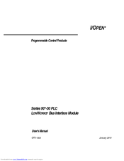
GE 90-30 PLC User Manual (93 pages)
interface between a Series 90-30 programmable logic controller (PLC) and a LONWORKS network Bus Interface Module
Brand:
GE
| Category:
Computer Hardware
| Size: 0.56 MB
Table of Contents
3
Technical Support
6
Related Publications
7
Table of Contents
11
Chapter 1 Overview
11
Table 1-1. Bus Interface Module Products
13
LON WORKS Network Overview
13
Table 1-2. Supported Topologies
15
Bus Interface Module Overview
16
Controls and Indicators
17
Connectors
18
Functional Characteristics
18
Configuration
18
Diagnostics
19
What You Need to Operate the Bus Interface Module
20
Table 1-7. Compatible CPU Models and Logicmaster 90 Software Versions
21
Chapter 2 Operation
22
Overview of Operation
22
Architecture
23
Figure 2-1. Overview of Bus Interface Module Operation
24
Operating Modes
24
Powerup Sequence
25
Figure 2-2. Bus Interface Module Powerup Sequence
26
Sweep Operation
28
Rack Location for the Bus Interface Module
29
Chapter 3 Hardware Installation
29
Module Installation and Removal
29
Module Installation
29
Module Removal
30
Network Installation
30
Network Wiring Guidelines
30
Terminating the Network
31
Connecting a Programmer
35
Chapter 4 Configuring the LBIM
35
Figure 4-2. Example: Assigning Network Variables Types to the LBIM and PLC Registers
36
Using the LBIM Configuration Software
36
Installation and Startup
37
Editing a Configuration
38
Module Configuration
40
Register Configuration
42
Table 4-1. Configuration Editor Fields
43
Reference Configuration
43
Field Definitions
45
Defining Variables
49
Table 4-2. Network Variable Fields in the Network Variable Editor
50
Menu Commands
52
File Menu
52
Tools Menu
55
Binding Network Variables
56
Table 4-3. Configurable Network Image Parameters
57
Chapter 5 Troubleshooting
58
Startup and Configuration
58
Table 5-1. Troubleshooting
59
Valid Bits
59
Wink Function
60
Appendix A Specifications
61
Module Specifications
61
Power Requirements
61
Environmental Requirements
61
Agency Approvals
62
Microprocessor Configuration
63
Interface Specifications
63
Serial Communications Protocol
63
Network Communications
63
Series 90-30 Backplane Interface
64
Appendix B Standard Network Variable Types
68
Appendix C Configuration File Specifications
68
Network Interface and PLC Mapping
69
Network Variable Parameter Configuration
71
Configuration Parameter Types
72
Appendix D Glossary
72
Appendix Glossary
73
Commonly Used Acronyms and Abbreviations
74
Glossary of Terms
80
Appendix E Quick Start Guide
81
Module Description
81
Functional Characteristics
83
Controls and Indicators
84
Connectors
84
Diagnostics
85
What You Need to Operate the Bus Interface Module
86
Hardware Installation and Powerup
87
Module Configuration/Network Installation
90
PLC Configuration
91
Summary
Share and save
Advertisement
Related Products
GE Series 90-30 PLC
GE 903759
GE 906
GE 900 MHz
GE MDS entraNET 900
GE Ultrospec 9000
GE 90.017.102
GE 98794
GE Autotrol Performa ProSoft 960 Series
GE 9900V-R
GE Categories
Refrigerator
Ranges
Microwave Oven
Air Conditioner
Dishwasher
More GE Manuals
Login
Sign In
OR
Sign in with Facebook
Sign in with Google
Upload manual
Upload from disk
Upload from URL