Sign In
Upload
Manuals
Brands
Fluke Calibration Manuals
Test Equipment
5322A
Fluke Calibration 5322A Tester Calibrator Manuals
Manuals and User Guides for Fluke Calibration 5322A Tester Calibrator. We have
2
Fluke Calibration 5322A Tester Calibrator manuals available for free PDF download: Operator's Manual, Calibration Manual
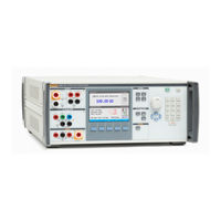
Fluke Calibration 5322A Operator's Manual (216 pages)
Multifunction Electrical Tester Calibrator
Brand:
Fluke Calibration
| Category:
Test Equipment
| Size: 8.9 MB
Table of Contents
Table of Contents
5
Introduction
9
Safety Information
10
Warnings
10
Symbols
12
Contact Fluke Calibration
13
Specifications
13
Service Information
13
Calibrator Functions
14
Function Descriptions
14
Other Features
16
Accessories
16
Included Accessories
17
Optional Accessories
18
Unpack and Inspect the Product
18
Power Considerations
18
Mains Power Cord
19
Mains Voltage
19
Ground the Product
20
Line Power and Fuse
20
Replace the Fuses
20
Select the Line Voltage
21
Install the Product in an Equipment Rack
21
Switch Power on
21
Operation Rules
23
Warm-Up Time
23
Front-Panel Operation
24
Front-Panel Feature Descriptions
24
Rear-Panel Features
28
Display Features
29
Control the Product
31
Select a Function
31
Help
31
Set the Output Signal Value
32
Numeric Keyboard
32
Cursor Key Editing
33
Edit Values with Rotary Knob Control
33
Readings
34
Connection/Disconnection of Output Terminals
34
Calibrator Setup Menu
35
Set a General Setup Function
35
Set the Beeper Volume
36
Set the Display Brightness
36
Enable/Disable the Beeper
36
Set Screen Saver
36
Set the Calibration Password
37
Set the Time
37
Set the Date
38
Set the User Interface Language
38
View the Device Information
38
Factory Settings
39
Product Functions
40
Set the Low Resistance Source Output
40
Output Selection
40
Set the High Resistance Source Output
43
Output Selection
44
Set the Ground Bond Resistance Output
47
Use the Ground Bond Resistance Mode
48
Use the Ground Bond Resistance Open Function
49
Use the Loop and Line Impedance Function
49
Line and Loop Residual Impedance
52
Select the Residual Impedance Correction Mode
53
Set the Manual Residual Impedance Correction Value
55
Set the Scanned Residual Impedance Correction Value
55
Set the Compensation Residual Impedance Correction Value
57
Set the Compensation of Test Lead Resistance Value
58
Use the Leakage Current Function
58
Passive Leakage Current
59
Differential Leakage Current
60
Active Leakage Current (5322A/VLC Only)
61
Substitute Leakage Current Mode
63
Use the RCD Test Functions
66
RCD Trip Current Function for Installation Testers
66
Power Line Voltage
69
Touch (Contact) Voltage
69
Trip Current Calculation
70
RCD Trip Time for Installation Testers
71
Power Line Voltage
73
Touch (Contact) Voltage
73
Output Terminals Reconnection
76
RCD Trip Time for Pats
77
AC/DC Voltage Outputs (5322A/VLC Only)
78
Measure with the Built-In Multimeter
81
Function Selection
82
Multimeter Input Selection
84
HIPOT LC Function
84
HIPOT Timer Function
88
Flash V (Voltage) Function
89
Flash LC (Leakage Current) Function
90
Remote Operation
91
Using the IEEE 488 Port for Remote Control
91
IEEE 488 Bus Restrictions
91
Set up the IEEE 488 Port
92
Use the USB Port for Remote Control
92
Set up the USB Port
93
Exceptions for USB Remote Control
94
5320A Remote Emulation
94
Remote Interface Factory Settings
94
Command Syntax Information
95
Parameter Syntax Rules
95
Terminators
96
Description of Abbreviations
96
Numeric Output Format
97
Supported SCPI Commands
97
SCPI Command Summary
98
System Command Summary
110
Status Command Summary
110
Common Command Summary
111
SCPI Command Details
112
Using the Output Commands
112
Using the Source Commands
112
Using System Commands
153
Status Subsystem
155
IEEE 488.2 Common Commands
157
Standard Status Data Structures
159
SRE Service Request Enable Register
160
ESR Event Status Register
161
ESE Event Status Enable Register
161
IEEE 488 Interface Configuration
163
Operator Maintenance
164
Clean the Ground Bond Resistance and Loop/Line Impedance Relays
165
Access the Fuses
166
Line-Power Fuse
166
Measurement Input Fuses
166
Clean the Air Filter
167
Clean the Exterior
168
Product Error Messages
169
What to Do in Case of Product Failure
172
DUT Calibration Examples
172
Calibrate Continuity Testers
173
Calibrate Earth Resistance Testers
174
Calibrate Insulation Resistance Testers
175
Calibrate Hand Crank Insulation Testers with the 5 Kv High Resistance Option
178
Calibrate Insulation Resistance Testers with the Resistance Multiplier
179
Limitations of the Resistance Multiplier
183
Resistance Multiplier Internal Schematic
184
Types of Megohmmeters and Use of the Resistance Multiplier
185
Sources of Mistakes When Using the Multiplier
186
Calibrate Ground Bond Resistance Testers
187
Calibrate Ground Bond Resistance Function in HIPOT Testers
189
Calibrate Line Impedance Testers
190
Calibrate Loop Impedance Testers
192
Calibrate Leakage Current Testers
193
Passive, Differential, and Substitute Leakage Current Calibration
193
Calibrate Residual Current Device (RCD) in Installation Testers
195
Calibrate RCD Trip Time
195
Calibrate Using 0.5 I Multiplier
195
Calibrate with 1 X I Multiplier
197
Calibrate with 1.4XI, 2 X I, and 5 X I Multipliers
198
Calibrate RCD Trip Current
199
Calibrate Residual Current Device (RCD) in Pats (Portable Appliance Tester)
200
Calibrate AC and DC Voltage (5322A/VLC Only)
202
Calibrate Load Test for Appliance Testers
205
Perform Flash Class I and Flash Class II Tests on (PAT) Portable Appliance Testers
207
Calibrate Hipots
211
Measure High Voltage with the HV Input
211
Measure High Voltage with the 10 Kv Divider Probe
212
Measure High Voltage with the 80K-40 High Voltage Probe
213
Measure Leakage Current with the 5322A-LOAD
214
Advertisement
Fluke Calibration 5322A Calibration Manual (102 pages)
Multifunction Electrical Tester Calibrator
Brand:
Fluke Calibration
| Category:
Test Equipment
| Size: 3.9 MB
Table of Contents
Table of Contents
3
Introduction
7
Contact Fluke
7
Service Information
7
Safety Information
8
Specifications
8
Theory of Operation
8
Low-Resistance Source (LVR Board)
10
High-Resistance Source (HVR/HVRB Board)
10
Ground Bond Resistance Source (REL Board)
11
AC/DC Voltage Adjustment (VCAL + AMP Board)
11
AC/DC Multimeter (MER Board)
12
Loop/Line Impedance (REL+COMP Board)
13
RCD Function (REL
14
RCD in PAT Function (RCD Board)
15
Passive and Differential Leakage Current (IFC+LVR Board)
16
Active Leakage Current (IFC+LVR Board, Optional)
17
Substitute Leakage Current (LVR Board)
17
Calibration
18
Calibration Mode
18
Adjustment Principles
19
The Calibration Menu Summary
19
Access the Calibration Procedure
20
Select the Calibration Type
20
Types of Adjustment Points
21
Terminate the Calibration Process
26
Adjustment Procedures
27
Ground Bond Resistance Adjustment
27
Low-Resistance Source Adjustment
30
High Resistance Source Adjustment 5 Kv (Optional)
32
High Resistance Source Adjustment 1.5 Kv
35
Ground Bond Resistance Meters Adjustment
38
Low Resistance Source Meters Adjustment
40
High Resistance Source Meters 5 Kv Adjustment (Optional)
42
Voltmeter Adjustment HVR V01-HVR V09
42
Ammeter Adjustment HVR I01
44
GW Input Resistance Calibration
45
High Resistance Source Meters 1.5 Kv Adjustment
45
Voltmeter Adjustment HVR V01-HVR V04
46
Ammeter Adjustment HVR I01
47
DC Voltage Calibrator Adjustment (Optional)
48
AC Voltage Calibrator Adjustment (Optional)
49
DC Multimeter Adjustment
51
DC Ranges for 10 V, 100 V, 1000 V Calibration
51
DC Range 5000 V Adjustment
52
DC Current Ranges 0.3 A, 3 A, 30 a Adjustment
54
AC Multimeter Adjustment
55
AC Ranges 10 V, 100 V, 1000 V Adjustment
56
AC Range 5000 V Adjustment
57
AC Current Ranges 0.3 A, 3 A, 30 a Adjustment
58
RCD Trip Current Adjustment
59
Leakage Current Adjustment
62
HV Probes Adjustment
63
High Resistance Multiplier Adjustment
64
Loop & Line Impedance Adjustment
64
DC HIPOT Leakage Current Adjustment
64
AC HIPOT Leakage Current Adjustment
66
HIPOT Ripple Adjustment
67
Verification
68
Product Configuration
68
Basic Verification Step
68
Conditions
70
Ground Bond Resistance and Loop/Line Resistance Verification Procedure
70
Low Resistance Source Verification
72
Kv and 1.5 Kv High Resistance Source
73
Voltage Calibrator
76
Leakage Current
77
RCD Function
78
Meter
79
High Voltage Tests
81
Verification Tables
83
List of Error Messages
94
Maintenance
96
Clean the Ground Bond Resistance and Loop/Line Impedance Relays
97
Access the Fuses
97
Line-Power Fuse
97
Measurement Input Fuses
98
Advertisement
Related Products
Fluke Calibration 55 Series
Fluke Calibration 5520A-PQ
Fluke Calibration 5520A-PQ/3
Fluke Calibration 5522A/6
Fluke Calibration 5522A-PQ
Fluke Calibration 5080A
Fluke Calibration 5560A
Fluke Calibration 5540A
Fluke Calibration 5522A-PQ/6
Fluke Calibration 5500A
Fluke Calibration Categories
Test Equipment
Measuring Instruments
Water Pump
Monitor
Industrial Electrical
More Fluke Calibration Manuals
Login
Sign In
OR
Sign in with Facebook
Sign in with Google
Upload manual
Upload from disk
Upload from URL